SeeMeCNC Rostock MAX v2 User manual

Rostock MAX v2 User's Guide
Welcome to the User's Guide for the Rostock MAX v2.0 3D printer.
ersion 1.52, September 28th, 2016
First Edition
Covers MatterControl v1.4
Copyright 2015 by Gene Buckle
Licensed as Creative Commons Attribution-ShareAlike 3.0
Questions or corrections should be emailed to geneb@deltasoft.com
- 1

Rostock MAX v2 User's Guide
Read Me First!
This document is your instruction manual for your new SeeMeCNC® 3D printer machine.
Before using your new 3D printer, thoroughly read and understand this manual for safe and effecti e
operation of the machine.
- 2
Warning
Adult supervision required. Children under 18 years of age require supervision.
Risk of Fire. Do not leave machine unattended.
Use genuine parts manufactured or designated y SeeMeCNC.
Keep a copy of this manual near the machine, easily accessi le to all operators.
Use of this machine is at your own risk.
Personal property damage, serious injury or death can result from not following
instructions or warning in the manual or misuse of the machine.
Automatic machine can start unexpectedly. Pay close attention and keep clear
while power is connected to the machine
The machine power supply is connected to AC voltage
and can e hazardous. Disconnect power efore
servicing this machine.
The hot end of the machine can reach very high
temperatures of 700F and can cause serious urns.
The heated print surfaces (heated ed) can also reach
temperatures high enough to cause severe urns. Allow
oth to cool for 20 minutes after turning off power.
Use caution near moving parts of the machine. Keep
ody and loose articles clear.
Poisonous gas, smoke, or fumes could e emitted y some materials you could
use with the machine. In such case, you should install ventilation.
Choking Hazard. This machine contains small parts and
can produce small parts which can e a choking hazard
to children.
Visit http://www.seemecnc.com to contact us if you have any questions.

Rostock MAX v2 User's Guide
Table of Contents
READ ME FIRST!.....................................................................................................................................2
0 – Introduction and Acknowledgments....................................................................................................4
1 – Driver and Software Installation..........................................................................................................5
1.1 – Installing the RAMBo Driver..................................................................................................5
1.2 – Installing the Arduino IDE......................................................................................................7
1.3 – Configuring the Arduino IDE..................................................................................................8
1.4 – Test Upload..............................................................................................................................9
1.5 – Uploading Repetier-Firmware...............................................................................................11
1.6 – The LCD and Front Panel Controls.......................................................................................13
2 – Installing MatterControl and Calibrating the Printer.........................................................................16
2.1 – Downloading, Installing, and Configuring MatterControl....................................................16
2.2 – Initial Function Tests.............................................................................................................22
2.3 – Setting the Z Height...............................................................................................................27
2.4 – Motion Calibration.................................................................................................................29
2.5 – erifying Extruder Stepper Operation...................................................................................32
2.6 – Extruder Calibration..............................................................................................................32
3 – First Print: PEEK Fan Shroud............................................................................................................34
3.1 – Configuring the Slicer............................................................................................................34
3.2 – Printing The PEEK Fan Shroud.............................................................................................36
3.3 – Loading Filament...................................................................................................................37
3.4 – Preparing the Heated Bed......................................................................................................38
3.5 – Printing the PEEK Fan Shroud..............................................................................................39
3.6 – Installing the PEEK Fan and Shroud.....................................................................................41
4 – Second Print: Layer Fan Shroud........................................................................................................44
5 – Matter Control Basics: Slicing...........................................................................................................47
6 – MatterControl Basics: Loading and Printing Objects........................................................................61
7 – Advanced MatterControl: Configuration...........................................................................................67
8 – Advanced MatterControl: Settings – General....................................................................................71
9 – Advanced MatterControl: Settings – Filament..................................................................................81
10 – Advanced MatterControl: Settings – Printer....................................................................................85
11 – Using the 3D and Layer iews.........................................................................................................88
12 – A Strategy for Successful (and great!) Prints...................................................................................97
Appendix A: Maintenance and Troubleshooting....................................................................................110
Print Layer Issues..........................................................................................................................111
Machine Won't Move!...................................................................................................................113
LCD Panel Not Working...............................................................................................................113
Appendix B: Alternate Calibration Method...........................................................................................115
Appendix C: The MatterControl Touch.................................................................................................119
Appendix D: Printing From the SD Card...............................................................................................126
Appendix E: Optimizing The Temperature Control Algorithms............................................................127
- 3

Rostock MAX v2 User's Guide
0 – Introduction and Acknowledgments
I’d like to welcome you to the 1st Edition of the Rostock MAX v2 User's Guide!
Acknowledgments
I'd like to thank the gentleman that runs http://minow.blogspot.com.au/ for his excellent guide
on calibrating delta configuration 3D printers.
I'd also like to thank the whole gang over at the SeeMeCNC forums for providing excellent
feedback. This would be a much lesser creation without their contributions and insights.
0 – Introduction and Acknowledgments - 4

Rostock MAX v2 User's Guide
1 – Driver and Software Installation
The Rostock MAX v2 does not include the firmware required to operate it. This was a
conscious decision by SeeMeCNC to encourage builders to become more proficient in the operation of
their new 3D printer.
Downloading the tools necessary to build and upload Repetier-Firmware is simple and easy.
However, before you get to that point, you're going to need to install a driver in order to communicate
with the RAMBo controller. If you're using MacOS or Linux, you can skip the driver installation
instructions.
1.1 – Installing t e RAMBo Driver
Download the USB Driver zip file from this location:
http://download.seemecnc.com/Software/RAMBo_USBdriver.zip
The driver will work with all versions of Windows – XP to v8.1.
If you haven't done so already, connect the Rostock MAX to your computer using the included
USB cable and turn the Rostock MAX on using the power switch you installed previously.
Unzip the file to a temp directory or other place that you know the location of. For Windows
users (and likely XP, Windows 8 and Vista users as well , plug in the RAMBo and let Windows “fail”
to find the correct driver for the board. Open up the device manager by right-clicking on “Computer” or
“My Computer” and select “Properties” followed by “Device Manager”. Scroll down to the “Unknown
Devices” entry and right-click on the RAMBo entry. Choose “Update Driver” and then “Browse my
computer for driver software” (or something similar to this . Choose “Let me pick from a list of device
drivers on my computer”, then click the button for “Have Disk”. Browse to where you unzipped the file
you downloaded and then click “OK”. It may complain (depending on OS that the driver isn’t signed –
allow it to install it anyway. That’s all there is to it. The RAMBo will now appear on your computer as
a standard serial port. On my computer it appeared as COM10 – it will most likely be different on
yours.
1 – Driver and Software Installation - 5

Rostock MAX v2 User's Guide
The easiest way to find out what port your RAMBo is listening on is to open up the Device
Manager and look for the RAMBo entry. In order to discover this bit of information, you'll need to
open up Device Manager (right click on My Computer, click “Properties” and then click “Device
Manager” . You'll get a window that looks something like this:
The entry we're looking for is highlighted
in green. Your “COM” entry will more than likely
be different from mine. Write this entry down as
you'll need it very soon.
1 – Driver and Software Installation - 6
Fig. 1.1-1: The RAMBo in the Device Manager

Rostock MAX v2 User's Guide
1.2 – Installing t e Arduino IDE
In order to compile and upload the firmware to the RAMBo controller, you're going to need the
Arduino IDE. This is an open source software development environment targeted at the Arduino
family of ATMega-based microcontroller project boards. At its heart, the RAMBo controller is just an
Arduino Mega 2560 with a lot of goodies attached to it.
You can download the Windows, MacOS and Linux version of the Arduino IDE from here:
http://arduino.cc/download
The version of the IDE used as of this writing is 1.6.1, but later versions can be used.
Install the Arduino IDE using the downloaded installer.
Now you need to download the firmware from SeeMeCNC's github repository.
https://github.com/seemecnc/Firmware/archive/master.zip
Unpack the “master.zip” file that you downloaded into a directory where you can keep track of
it. You may need to reference it in the future.
Start the Arduino IDE – you should be presented with a screen that looks similar to this:
1 – Driver and Software Installation - 7
Fig. 1.2-1: The Arduino IDE

Rostock MAX v2 User's Guide
1.3 – Configuring t e Arduino IDE
Before we can use the IDE to upload the firmware to the RAMBo controller, we need to tell the
Arduino IDE what kind of board we have and what communications port it needs to use in order to
perform the upload task.
Click on the “Tools” menu item and then click on “Board” and then “Arduino Mega or Mega
2560”.
Next, you'll need to tell the Arduino IDE what port to talk to the RAMBo on. To do this, click on
“Tools”, “Serial Port” and then choose the COM port that your RAMBo appears as on your computer.
1 – Driver and Software Installation - 8
Fig. 1.3-1: hoosing the board type.
Fig. 1.3-2: hoosing the Serial Port.

Rostock MAX v2 User's Guide
1.4 – Test Upload
Ok, now that you've got the Arduino IDE configured, we're going to do a quick task that'll do
two things. First, it will validate that you've got the Arduino IDE configured properly and that you're
able to connect and upload a program to the RAMBo controller. Remember – the RAMBo controller is
just an Arduino Mega 2560 with a bunch of goodies piled on top!
Second, the program I'm going to have you run will clear the EEPROM on the RAMBo
controller to make sure you start with a clean slate. The EEPROM is an Electrically Erasable
Programmable Read Only Memory and it's where Repetier-Firmware will store settings. When you can
store configuration information in the EEPROM, it means that you don't have to re-upload the
firmware every time you make a change.
Click on “File”, “Examples”, “EEPROM”, and finally “eeprom_clear” as highlighted in blue in
the figure below.
The only thing you need to do now is click the “Upload” icon in the Arduino IDE. The upload icon is
represented by this symbol:
1 – Driver and Software Installation - 9
Fig. 1.4-1: Loading the eeprom_clear program.
Fig. 1.4-2: eeprom_clear loaded & ready to go.

Rostock MAX v2 User's Guide
Turn your Rostock MAX v2 on if you haven't already and then click the Upload icon.
When the upload is finished, you should see
results similar to that on the right. The “Done
uploading” is the status you want. There is no other
external evidence that the eeprom_clear program has
done its job, but it has!
1 – Driver and Software Installation - 10
Fig. 1.4-3: Success!

Rostock MAX v2 User's Guide
1.5 – Uploading Repetier-Firmware
Now it's time to load Repetier-Firmware into the Arduino IDE and upload it to the RAMBo
controller! Click “File”, “Open” and browse to where you unpacked the master.zip file you
downloaded from the SeeMeCNC github repository. Select the file “Repetier.ino” and click the Open
button. Note that Windows may hide the program suffix (.ino) from you.
Before you can upload the firmware to the RAMBo, you're going to need to make two small
changes to how the firmware is configured. Once you have the firmware loaded in the Arduino IDE,
click on the tab marked Configuration.h.
Now scroll down a short way until you see the section that matches the figure below.
You'll need to make sure that the MOTHE BOA D
definition is set to “301” for the RAMBo board and the
P INTE option is set to “2” for the Rostock MAX v2. Click
on the Save icon to save your changes.
1 – Driver and Software Installation - 11
Fig. 1.5-1: Opening Repetier.ino
Fig. 1.5-2: The onfiguration.h tab in the editor.
Fig. 1.5-3: onfiguration options.
Fig. 1.5-4: Save changes!

Rostock MAX v2 User's Guide
Now you can click on the Upload icon to send the firmware to the RAMBo!
Depending on the speed of your computer, this could take up to a few minutes to accomplish.
Be patient and wait for the “Done uploading.” status to appear just like it did when you uploaded the
“eeprom_clear” program.
You may see a warning similar to the one shown below. This is strictly an advisory message
and won't affect how the firmware works with your Rostock MAX.
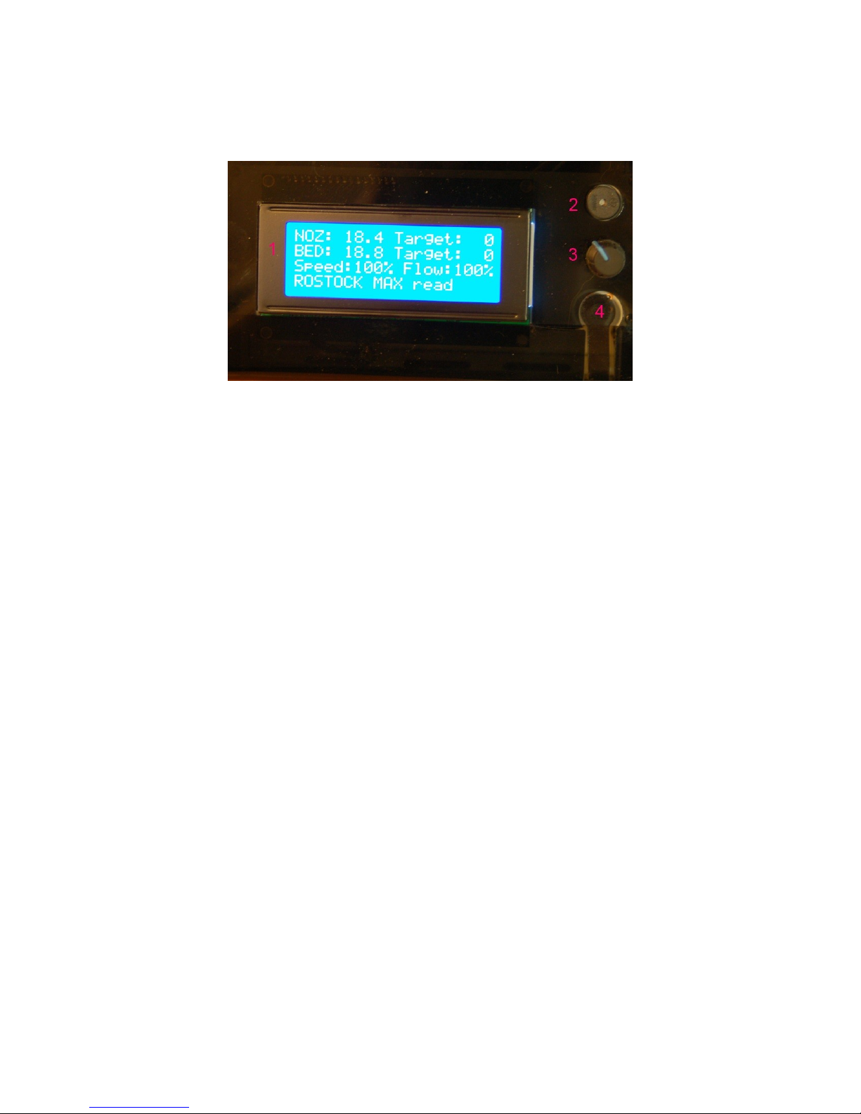
When the upload has finished the RAMBo will restart and you should see the following display
on the LCD:
Congrats again! You've got a living, breathing (hey, work with me here!) 3D printer that you've
built yourself. If for some weird, inexplicable reason you do NOT see that display (or something very,
very similar!), carefully retrace your steps. Start back at the beginning with the eeprom_clear test and
go from there. If you still don't get a working display please check Appendix A, or contact
1 – Driver and Software Installation - 12
Fig. 1.5-5: It's ALIVE!
Fig. 1.5-5: ompiler advisory message.

Rostock MAX v2 User's Guide
1.6 – T e LCD and Front Panel Controls
Let's go over what information the LCD displays and what the front panel controls do.
1. Nozzle Temperature. This is the temperature at the nozzle as measured by the thermistor
that you installed when you put the hot end together. It reads in degrees Celsius – you'll
find quickly that just about everything to do with 3D printing is done in Metric units of
measure. FYI, 18.4C is 65.12F.
2. Target Nozzle Temperature. When you're printing a part, this field will show you what
temperature you've set the hot end to.
3. Bed Temperature. This is the temperature of the Onyx heated bed as measured by the
thermistor that you installed in the center of the bed. Just like the nozzle, it reads in
Celsius.
4. Target Bed Temperature. This displays the temperature that you've set the Onyx to heat
to.
5. Speed Rate. This is the speed multiplier field. Normally it will read 100%, but if you've
changed the speed control from MatterControl, this number will display what that
setting is. We'll get into this in more detail later.
6. Flow Rate. This shows the current flow rate of the extruder. This is also a field that is
controlled from MatterControl.
7. Status Line. This is a multipurpose display field that will change depending on what the
printer is currently doing.
1 – Driver and Software Installation - 13
Fig. 1.6-1: Default L D display.
Rostock MAX v2 User's Guide
The front panel:
1. The LCD Display. (but you knew that, right?)
2. Beeper. That's it does. Beeps. (and beeps, and beeps and beeps...)
3. Input Controller. Turning the knob clockwise & counter clockwise is how you navigate
through the LCD menus. Pressing the button straight in acts similarly to a mouse click –
it selects the current menu item.
4. Emergency Reset Button. When you hit that button, a number of things are going to
happen. First, the RAMBo is going to turn off both the heat bed and the nozzle heaters.
Next, it's going to send all three Cheapskates to their “home” positions at the top of the
Rostock MAX v2 and then the RAMBo controller will reboot itself. If the printer is
really going nuts on you, this is the second fastest way to make it behave. (The first is to
turn the power off!)
Note that in order to operate the reset button, you need to press hard. You'll hear it
click, but that's kind of deceptive. The button doesn't close until more force is applied to
the little reset button arm. It is somewhat of a safety feature to prevent accidental resets
during a print job.
1 – Driver and Software Installation - 14
Fig. 1.6-2: The Front Panel.

Rostock MAX v2 User's Guide
The last thing I'm going to cover in this section is the “activity” display that the LCD can show
you. Turn the knob either direction and you'll get a display that looks something like this:
This will tell you at a glance how much time your Rostock MAX v2 has spent printing and how
much filament it's used in the process. The time display breaks down into days, hours and minutes.
The filament display shows filament used in fractional meters.
Now let's get this thing calibrated and printing!
1 – Driver and Software Installation - 15
Fig. 1.6-3: Activity display.

Rostock MAX v2 User's Guide
2 – Installing MatterControl and Calibrating t e Printer
This is the fun part! The Rostock MAX v2 3D printer is very easy to calibrate, but it can take
some time and a number of iterations to get it as good as you can. You'll want to take your time here
because the better you calibrate the printer, the better it will perform.
2.1 – Downloading, Installing, and Configuring MatterControl
The “host” software of choice for the Rostock MAX is called MatterControl.
MatterControl is a full featured and multi-platform host interface for 3D printers. There are
other host interfaces out there such as Octoprint, Repeiter-Host, and Pronterface, but this guide will
only cover MatterControl. MatterControl is available for Windows and MacOS platforms. If you've
got a Linux machine, you'll want to look into either Pronterface or Repetier-Host.
MatterControl can be downloaded from http://seemecnc.com/pages/downloads. Scroll down to
the “Software” section.
After the download completes, run MatterControl and click on “Add Printer” button as shown
below. This will open a dialog box that you'll use to select your printer model and give it a name.
Click in the “Printer Name” field and enter a name
for your Rostock MAX v2 3D printer. I've named mine
“Walter”. (Yes it's weird. I'm weird. Deal with it.)
Select “RostockMAX” from the “Select Model”
drop-down.
Note that since you're using the SeeMeCNC
customized version of MatterControl, the model drop-down
will only contain the models of SeeMeCNC made printers
as well as “Other” if you'd like to configure MatterControl
to use a non-SeeMeCNC printer in the future.
Click the “Save & Continue” button to continue.
2 – Installing MatterControl and Calibrating the Printer - 16
Fig. 2.1-1: Printer setup.

Rostock MAX v2 User's Guide
When you save the new profile, you'll be prompted to install a driver. Since you've already
installed the RAMBo driver to load the firmware on your new Rostock MAX v2, you can safely click
“Skip”.
When the new printer configuration is saved,
MatterControl will then try to auto-detect the printer. It does this
by attempting to interrogate printers on each serial port present on
your computer.
MatterControl can detect what kind of firmware it's
talking to based up on the response it gets for this step.
The dialog shown on the right is a bit unclear – the
MatterControl guys are assuming that you might have gotten
ahead of yourself. If you DID connect MatterControl (using the
CONNECT button), go ahead and click the DISCONNECT button and then bring the 3D Printer Setup
dialog to the front by clicking on it in the task bar.
Go ahead and click the Continue button. You'll be presented with a new dialog as shown below
on the left.
Make sure you've got the USB cable connected to
the RAMBo and your computer. Power on your Rostock
MAX v2 and then click the “Connect” button.
2 – Installing MatterControl and Calibrating the Printer - 17
Fig. 2.1-4: 3D Printer Setup.
Fig 2.1.-2: Driver dialog.
Fig. 2.1-3: onnecting to the printer.

Rostock MAX v2 User's Guide
If for some reason MatterControl cannot “see”
the Rostock MAX v2, you may see an error like the
one shown on the right.
If you do get this error, click on the “Manual
Configuration” link at the bottom of the dialog box.
The Manual Configuration link will bring up a dialog box that allows you to choose which
communication port your printer is connected to.
You'll be presented with a list of the serial
ports that MatterControl can currently “see”. If you
don't see any ports, or the one you need isn't listed,
then click the “Refresh” button at the bottom of the
dialog. If the port STILL does not appear, check to
make sure that the USB cable to the Rostock MAX
v2 is correctly connected and the printer is turned on.
If you still see no port after clicking Refresh, please
contact SeeMeCNC support!
If your port is listed, click on the little circle
to select it and then click the “Connect” button at the
bottom of the dialog. You should be rewarded with
the following dialog:
2 – Installing MatterControl and Calibrating the Printer - 18
Fig. 2.1-5: Oops!
Fig. 2.1-6: Manual onfiguration
Fig. 2.1-7: Serial port selection
Fig. 2.1-8: Success!

Rostock MAX v2 User's Guide
Click the “Done” button and let's continue!
Maximize the MatterControl window to see the entire main screen. If you shrink the size of the
main window, features “fold” away to keep from cluttering the display. It's actually pretty clever.
Before we get to the details of getting your printer calibrated, let's cover what features are
available from MatterControl. Because the MatterControl display does contain so much information,
I'm going to break it down into smaller segments to make the screen shots easier to see as I describe the
various components in MatterControl.
1. This is the print queue display. If
nothing is queued up, you'll see the
message, “No items in the print
queue”. To add an item, click the
“Add” button (#13). We'll cover this
in detail later. Note that you can
only select STL or GCODE files.
2. This is the temperature display. The
top number displays the current
nozzle temperature and the bottom
number covers the heated bed. Both
temperatures are displayed in
degrees Celsius.
3. Queue count. This lists the number
of objects currently loaded in the
print queue.
4. Library – this is a list of items that
you've stored in your object “library”. We'll cover this one in detail later as well.
5. Print History – Clicking here will show you information about your recent print jobs, including
their start & end times as well as whether or not the job was completed.
6. Settings & Controls – this is where you can edit your slicer & printer settings as well as
manually control your Rostock MAX v2.
7. The Edit button will allow you to choose which items in the print queue will be available for
printing.
8. The Export button will allow you to export the currently select item as an STL, AMF, or
GCODE file. You can use this to save GCODE to an SD card for stand-alone printing
2 – Installing MatterControl and Calibrating the Printer - 19
Fig. 2.1-9: Status & Print Queue Pane.

Rostock MAX v2 User's Guide
9. The Copy button will make copies of the currently selected item in the print queue.
10. The emove button will remove the currently selected item in the print queue.
11. The More drop-down will allow you to send the currently selected item to another device, or to
the print Library.
12. This is where you'll see items that are currently in your Queue.
13. The Add button will allow you to add objects or G-Code files to the print queue.
14. The Create button displays a list of available plug-ins that are used to create printable objects
right inside of MatterControl.
15. The Buy Materials button will open a browser and point it to the SeeMeCNC store.
16. The Queue button opens a menu list that will allow you to export the current file and perform
other operations on the print queue.
The right half of the MatterControl
interface is occupied by a 3D view of your
build platform and what objects are
currently loaded and ready to print.
1. iew manipulation controls – Reset
iew, Rotate, Pan, and Zoom. By default,
the 3D view will show a rotating display of
the part. You can stop the rotation by
clicking anywhere in the 3D view window.
2. The 3D and Layer view controls allow
you to switch between the 3D view
(shown) and the Layer view. The layer
view shows you the path the print head will
take as your part is printed. The layer view
won't display anything until the part you
want to print has been “sliced”.
3. The object currently ready to print.
4. This is a representation of your Rostock
MAX v2's print bed. As long as your
object fits within the circle, you should be
able to print it!
2 – Installing MatterControl and Calibrating the Printer - 20
Fig. 2.1-10: The Model Pane
Other manuals for Rostock MAX v2
3
Table of contents
Other SeeMeCNC 3D Printer manuals

SeeMeCNC
SeeMeCNC Rostock Max v3 User manual

SeeMeCNC
SeeMeCNC orion delta User manual

SeeMeCNC
SeeMeCNC Rostock MAX v2 User manual

SeeMeCNC
SeeMeCNC Rostock Max v3 User manual

SeeMeCNC
SeeMeCNC Artemis 300 User manual

SeeMeCNC
SeeMeCNC Artemis User manual

SeeMeCNC
SeeMeCNC rostock max v2.0 User manual

SeeMeCNC
SeeMeCNC ERIS DELTA User manual

SeeMeCNC
SeeMeCNC orion delta User manual

SeeMeCNC
SeeMeCNC Rostock MAX v2 User manual


