2
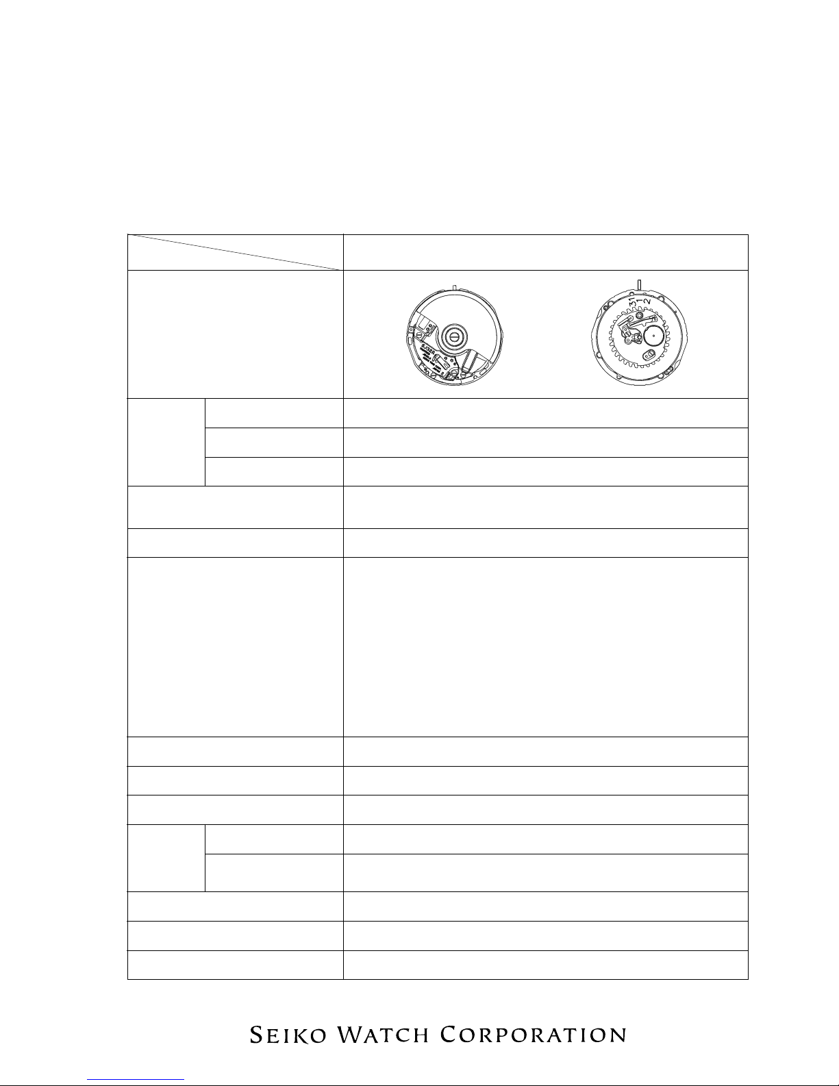
REMARKS ON REPAIRING CAL. 5J32A
Cal. 5J32A is an epoch-making model of SEIKO’s revolutionary KINETIC watches, just like 5J21A/5J22A. It
is equipped with innovative functions that have introduced a completely new concept into the KINETIC
technology SEIKO has cultivated in its long years of precision product manufacturing. In repairing Cal.
5J32A, therefore, you are requested to have the full knowledge of its functions and strictly observe the
repairing and checking instructions provided in this guide so that the watch will be repaired securely.
FEATURES OF CAL. 5J32A
Cal. 5J32A features the power save function that automatically stops the hands from moving if the watch is
left untouched for a certain period of time. When you decide to use it again, swinging the watch several times
will activate the time relay function, which starts the hands moving quickly to indicate the correct time and
resume the normal operation. In this way, Cal. 5J32A conserves the stored electrical energy by stopping the
hands while it is not in use, and, at the same time, it completely eliminates the cumbersome time setting
procedure when it is used again.
Thanks to this innovative mechanism, the duration of charge has increased enormously.
1. POWER SAVE FUNCTION
·While the watch is not in use, the hands stop automatically to minimize the electrical energy
consumed. This is called “the power save function”. Though the hands stop, the built-in IC continues
to compute the time, keeping the watch ready for the next use.
·The power save function can be activated either automatically or manually.
The automatic power save function
·If the watch is left untouched for approximately 72 hours, the power save function is automatically
activated.
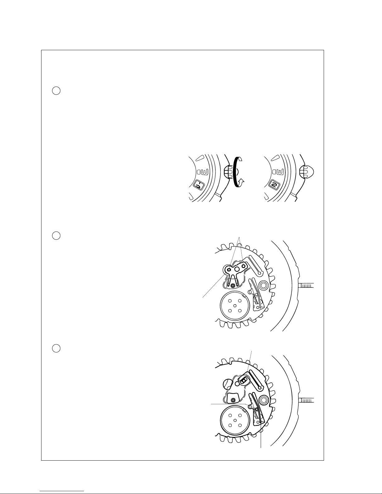
The manual power save function
·The power save function can be activated whenever you decide no to use the watch for a long time.
·By pulling out the crown to the first click and pushing it in to the normal position within one second,
the power save function is activated manually.
Notes:
*Do not pull out the crown to the second click while the power save function is in operation. Otherwise,
it is turned off, and the time retained inside the watch will be erased.
*While the second hand is moving at two-second intervals, the power save function cannot be activated
manually.
2. TIME RELAY FUNCTION
·While the power saving function is working, the built-in IC continues to compute the time though the
hands stop. As the watch detects a certain amount of electricity generated by swinging it, the hands
are automatically adjusted to the time retained inside the watch, resuming the normal operation. This
is called the “time relay function”. As it is activated, the hour and minute hands are adjusted first, then,
followed by the second hand.
·By only swinging the watch for 2 to 3 seconds, the time relay function will be activated.
Notes:
*The time relay function will not adjust the date. If you find the date incorrect after it is activated, it is
necessary to adjust the date manually to the current date.
*The accuracy of the time computation by the built-in IC is equivalent to that of conventional quartz
watches. If the power save function has been in operation for a long term before the time relay function
is activated, the time indicated by the hands may include a certain amount of time loss or gain that has
accumulated during that time.
3. DURATION OF CHARGE
·The duration of charge varies depending on the power reserve stored inside the watch. If the watch
is fully charged, the power save function will keep it operating for about four years.
Note: If the power reserve is depleted completely while the power save function is in operation, the time
relay function may not be activated by swinging the watch. Instead, the second hand starts moving
at two-second intervals.