English Espanol Francais
Safety Warnings Avisos de Seguridad Consignes de Sécurité
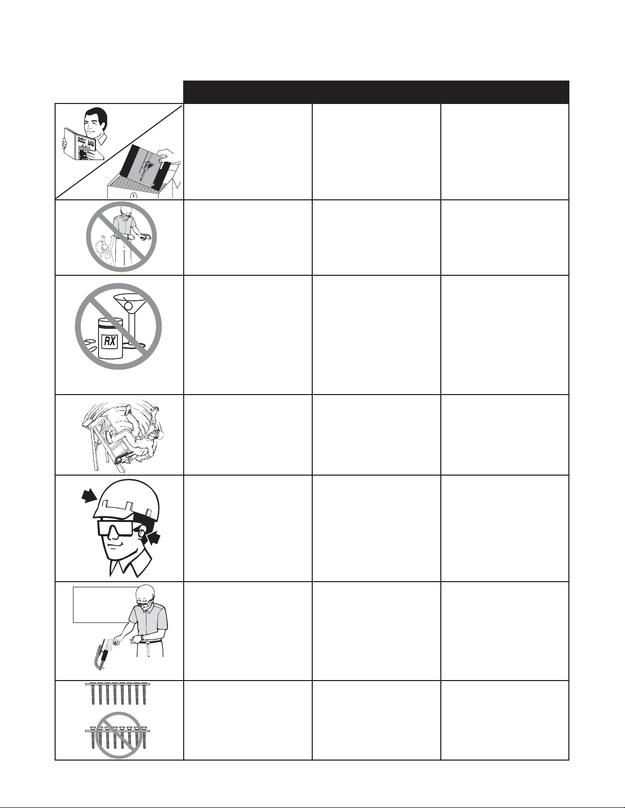
General Safety Rules
Read and understand all
instructions. Failure to follow
all instructions listed below,
may result in electric shock, fire
and/or serious personal injury.
SAVE THESE
INSTRUCTIONS
Warning!
Keep bystanders, minors, and
visitors away while operating a
power tool. Distractions can
cause you to lose control.
3
DS200-D2
DS200-D4
Warningsfor the safe use of this tool are included in this manual.
Losavisos para el uso seguro de esta herramienta están incluidos
eneste manual.
Lesconsignes pour l’utilisationen toute sécurité de cet outil se
trouventdans ce manuel.
OperatingInstructions
Instruccionesde Operacion
Moded’Emploi
?????
D600-2 D600-4
D600ATT
*SchematicDrawings Inside
©2007byRex Commercial Toolsand Fasteners, LLC
Questions?Comments?Contact: 1.800.396.3318
orvisitour website: www.tyrextools.com
Lea y comprenda todas las
instrucciones. La falta de ob-
servación de todas las instruc-
ciones listadas a continuación
puede causar choque eléctrico,
incendios o lesiones graves.
GUARDE ESTAS
INSTRUCCIONES
Advertencia! Avertissement !
Maintenez votre zone de
travail propre et bien éclai-
rée. Des établis en désordre
et des zones mal éclairées
augmentent les risques
d’accident.
CONSERVEZ CES
INSTRUCTIONS
Mantenga s los acompañantes,
menores y visitas alsjados mien-
tras usted utiliza la herramienta
de motor. Las distracciones
pueden hacer que usted
pierda el control.
Maintenez les spectateurs,
enfants et visiteurs à l’écart
lorsque vous utilisez de
l’outillage électrique. Toute
distraction risque de vous
faire perdre le contrôle de
votre outil.
Stay alert, watch what you are do-
ing, and use common sense when
operating a power tool. Do not
use tool while tired or under the
influence of drugs, alcohol, or med-
ication. A moment of inattention
while operating power tools
may result in serious personal
injury.
Personal Safety
Cuando utilice una herramienta de
motor, manténgase a;erta, preste
atención a lo que está haciendo y
aplique el sentido común. No use
la herramienta cuando se sienta
cansado o se encuentre bajo los
efectos de drogas, alchol o medi-
camentos. Un momento de falta
de atención mientras utiliza una
herramienta de motor puede
ocasionar lesiones graves.
Seguridad personal
Soyez en bonne condition phy-
sique, soyez attentif à ce que vous
faites et faites preuve de bon sens
lorsque vous utilisez un outillage
électrique. N’utilisez pas votre
outil si vous êtes fatigué ou sous
l’influence de drogues, alcool
ou médicaments. Un moment
d’inattention lors de l’utilisation
d’un outillage électrique peut
être la cause de graves bles-
sures corporelles.
Sécurité corporelle
Do not overreach. Keep
proper footing and balance
at all times. Proper footing
and balance enable better
control of the tool in unex-
pected situations.
No se estire para trabajar.
Mantenga en todo momento
una posición adecuada y
el equilibrio. La posición y
el equilibrio adecuados le
permiten contrilar mejor la
herramienta ante situaciones
inesperadas.
Ne présumez pas de vos
forces. Restez bien stable et
en équilibre à tout moment.
Une position stable et bien
équilibrée vous permettra de
mieux réagir à une situation
inattendue.
Use safety equipment.
Always wear eye protec-
tion. Dust mask, non-skid safety
shoes, hard hat, or hearing protec-
tion must be used for appropriate
conditions. Failure to do so could
result in personal injury.
Use equip de seguridad.
Use siempre protección
para los ojos. A fin de trabajar
en las condiviones apropiadas,
debe usar máscara para polvo,
calzado de seguridad antidesli-
zante, casco duro o protección
para los oídos. El no utilizar
estos elementos puede ocasionar
lesiones.
Utilisez des équipements de
sécurité. Portez toujours des
lunettes de protection. Utilisez
un masque de protection contre la
poussière, des chaussures antidéra-
pantes, un casque et des protections
auditives pour travailler dans les meil-
leures conditions. Un manquement à
ces règles de sécurité peut provoquer
des accidents corporels.
Tool service must be
performed only by
Authorized Senco repair
personnel. Service or
maintenance performed by
unqualified personnel may
result in a risk of injury.
Service Servicio técnico
L’entretien de l’outil ne
doit être assuré que par du
personnel autorisé et qualifié
de Senco . De l’entretien assuré
ou des réparations effectuées
par du personnel non qualifié
peuvent occasionner des
risques d’accident.
Entretien
Las tareas de servicio técnico
de la herramienta deben ser
realizadas sólo por personal
de reparaciones de Senco
autorizado. Las tareas de
servicio o mantenimiento
realizadas por personal no
clificado purden ocasionar
riesgos de lesiones.
Authorized
Service Center
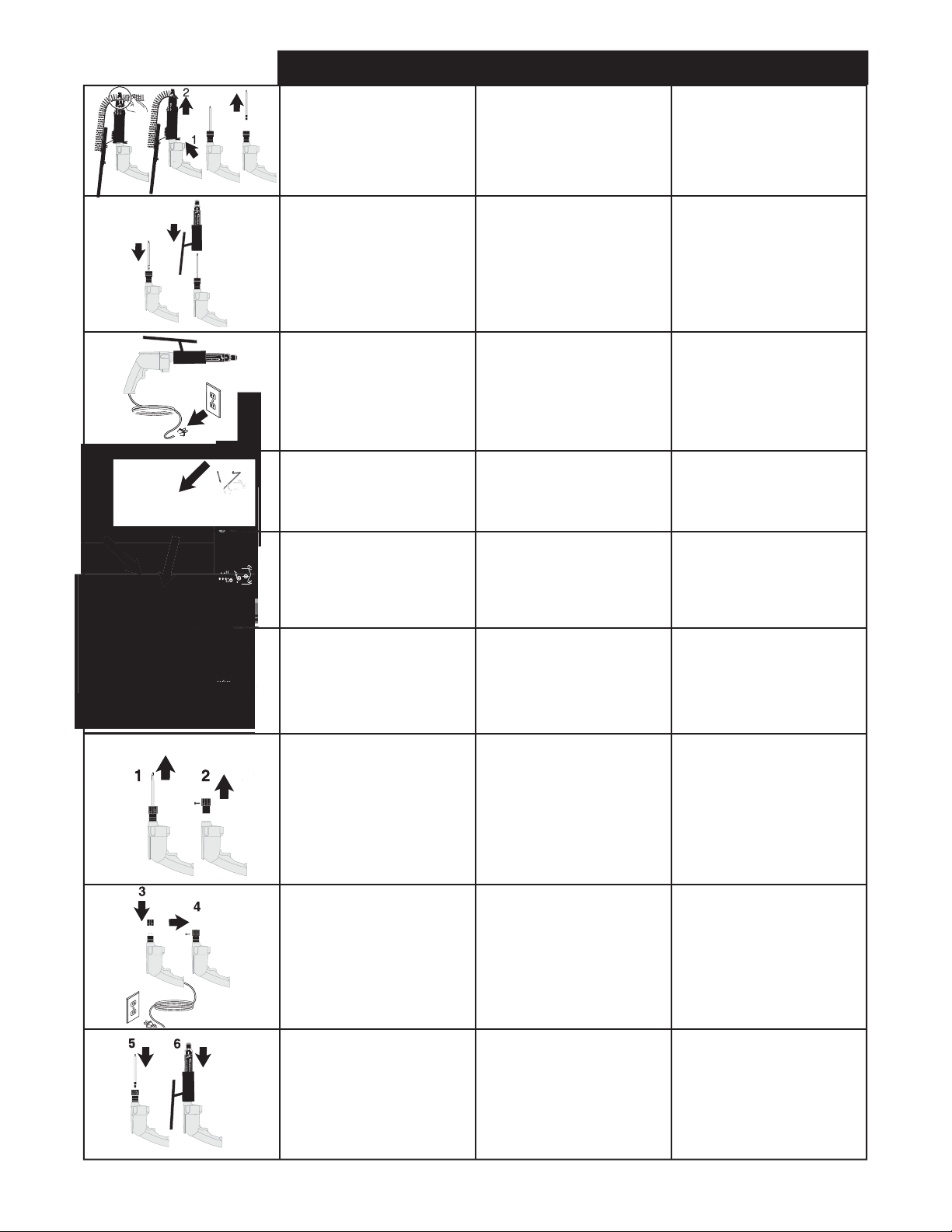
Loading the Tool:
Check to be sure the heads
of the screws are resting on
top of the plastic collation
material. This will prevent
damage to the strip guide.
Carga de la herramienta:
Asegúrese de que las cabezas
de los tornillos descansen
contra el material plástico de
intercalación. De este modo,
se evitarán daños a la guía de
la faja.
Chargement de l’outil :
Vérifiez que les têtes des vis
reposent bien sur le sommet de
la bande collectrice en plastique
pour éviter d’endommager le
guide.