6
OPERATION
3.1 SPECIFIC SAFETY INSTRUCTIONS
●Before starting work, make sure that the safety and trig-
ger devices are working perfectly and that all screws and
nutsarermlytightened.
●Do not manipulate the stapler in any way.
●Do not dismantle or block any part of the stapler. This ap-
plies in particular to the trigger safety mechanism!
●Do not perform any „emergency repairs“ using inappropri-
ate methods.
●Ensure that the stapler undergoes regular and proper
maintenance.
●Avoid any weakening or damage to the stapler, e.g. from
- knocking or engraving
-modicationworknotauthorisedbythemanufacturer
- working on templates made of hard material (e.g. steel)
-droppingorpushingovertheoor
- using it as a hammer
- any type of violent force.
3.2 CONNECTION TO THE COMPRESSED AIR SUPPLY
3.2.1 Requirements for the compressed air supply
Toensurethatthestapleroperates,perfectlyltered,dry,
oiledcompressedpressureisrequiredinsufcientquan-
tities (see chap. 1.2, „Technical data“). Observe the fol-
lowing points when selecting the compressed air supply:
●If the pressure in the supply network is higher than the
permissible operational pressure of the stapler (8.3
bar), an additional pressure control valve (pressure
regulator) with a downstream pressure control valve
must be installed in the supply line.
●When compressed air is generated by a compres-
sor the natural atmospheric humidity condenses. This
condensation must be removed by a moisture trap.
Otherwise corrosion can begin in the compressed air
system and in the stapler and cause wear and tear.
●Permanently installed lines for the compressed air
system should have an internal diameter of at least 19
mm. The hose connection to the stapler should have an
internal diameter of at least 8 mm.
●Compressed air lines should be laid with a downward
slope from the compressor to the consumer.
●Terminals for consumers should be connected to the
upper side of permanently installed compressed air
lines.
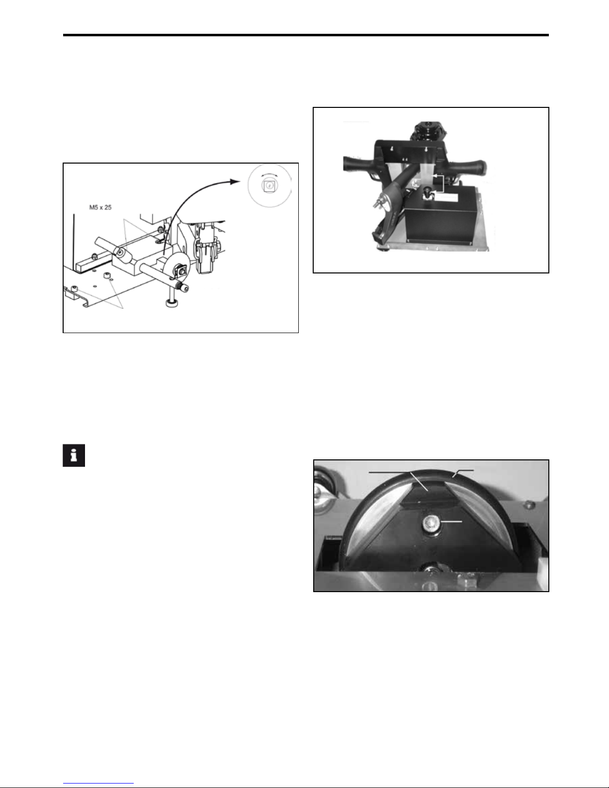
3.2.2 Lubrication
If there is no maintenance unit, oil the air inlet on the
stapler with SENCO pneumatic oil; under normal op-
erational conditions 5-10 drops twice daily is enough.
3.2.3 Connection
To connect the stapler to the compressed air supply
carry out the following steps:
1. Ensure that the pressure in the compressed air system
does not exceed the permissible operational pressure
of the stapler (8.3 bar).
2. Set the air pressure at the lowest level of the recom-
mendedoperationalpressure(6bar).
3. Empty the magazine to avoid a staple from being eject-
ed in the following steps. This could happen if parts of
the stapler are not in the starting position due to previ-
ous maintenance or repair work or due to transport.
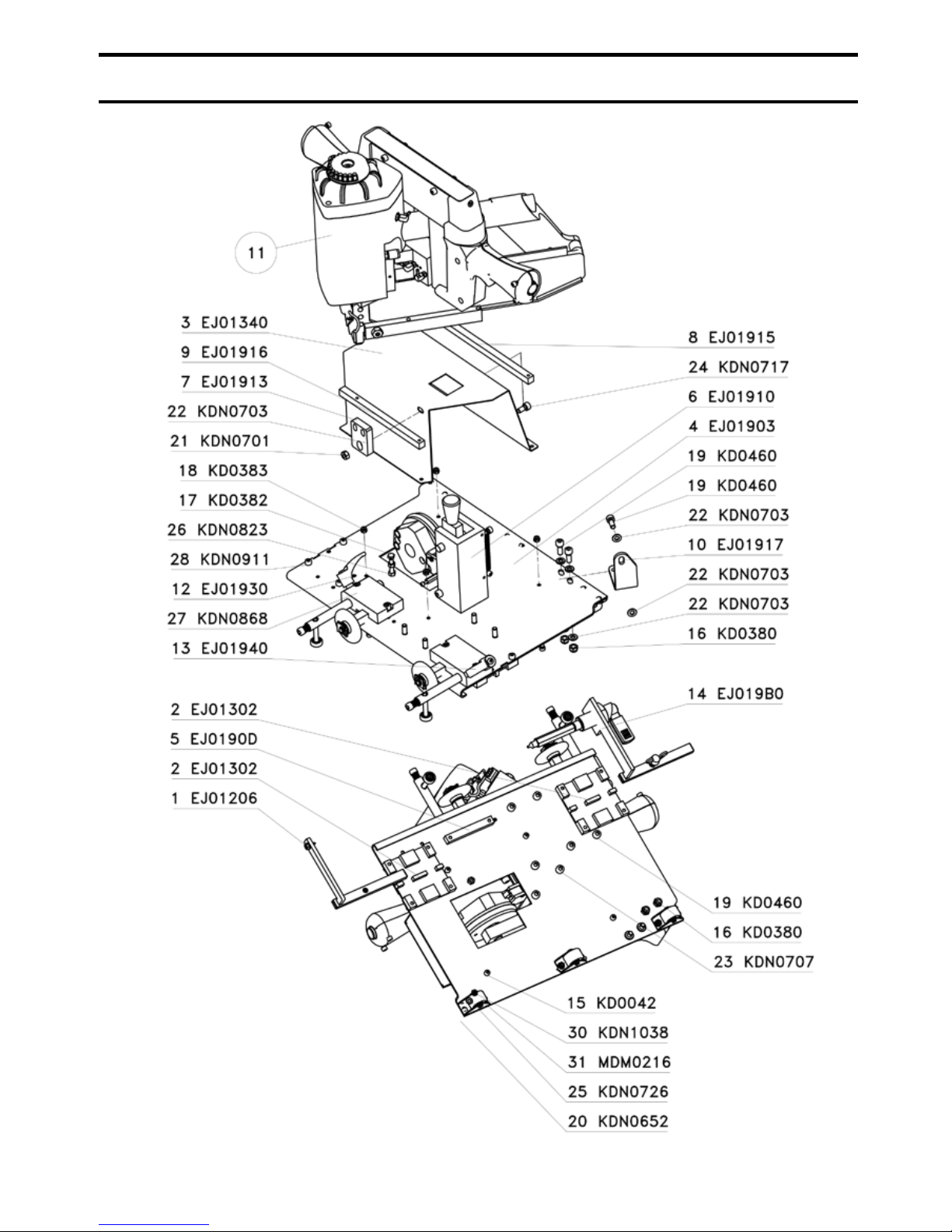
4. Connect the connecting nipple (11) on the stapler to
the compressed air supply using a hose connection
equipped with quick connectors.
5. Make sure the stapler is working perfectly.
To do this, place the outlet on a piece of wood or wood-
work.
- Now pull the stapler towards you without activating the
trigger. The system should not be set off.
- Repeat the process with an activated trigger. The sys-
tem should now be set off at regular intervals.
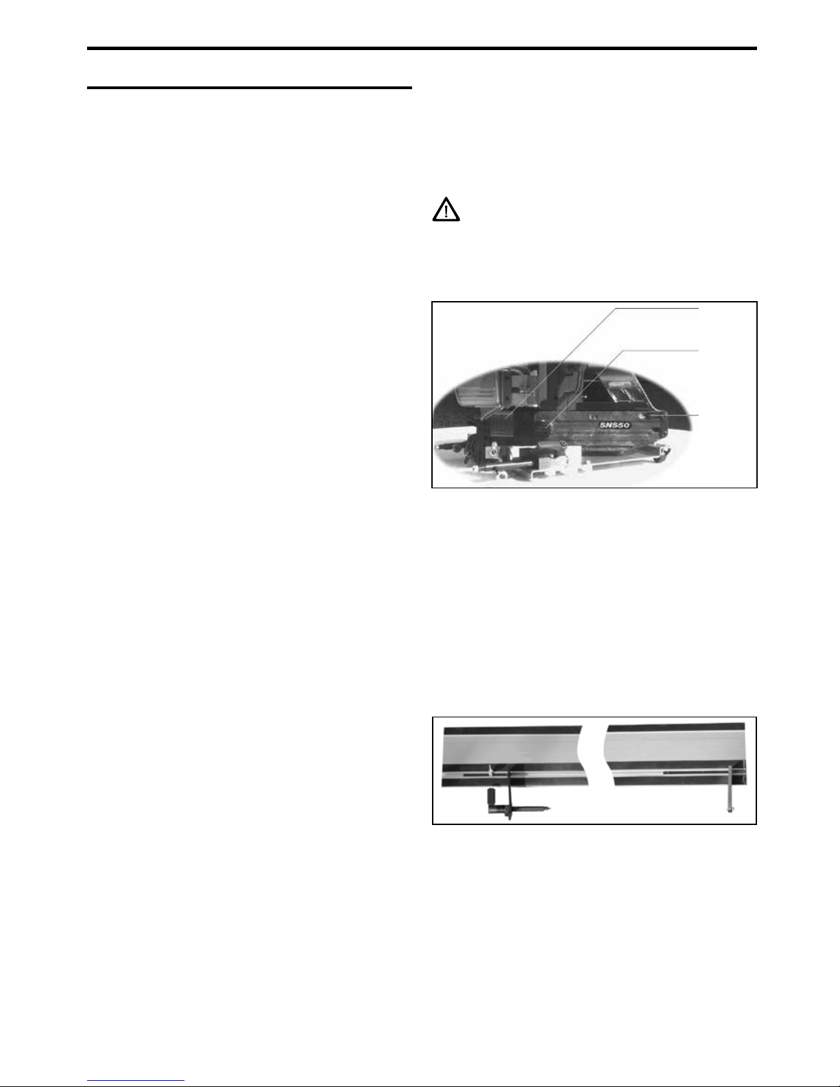
3.3 FILLING THE MAGAZINE
DANGER
IF INCORRECT STAPLES ARE USED, SAFE OPERA-
TION CANNOT BE GUARANTEED. FOR THIS REASON
YOU SHOULD ONLY USE STAPLES APPROVED BY
THE MANUFACTURER (SEE CHAP. 1.2, „TECHNICAL
DATA“).
Tollthemagazinecarryoutthefollowingsteps:
1. Disconnect the system from the compressed air supply.
2. Pull the staple slide so far back that the rest snaps into
place.
3. Place the staple block with the tips facing down into the
magazine.
4. Unlock the staple slide by pressing on the rest. Let the
staple slide glide forward.
5. Reconnect the compressed air supply.
To empty the magazine, repeat the procedure in reverse.
Staple
supply
Staple
slide
(closed)
Rest for
staple
slide
llustration 3.3/1: Filling the magazine
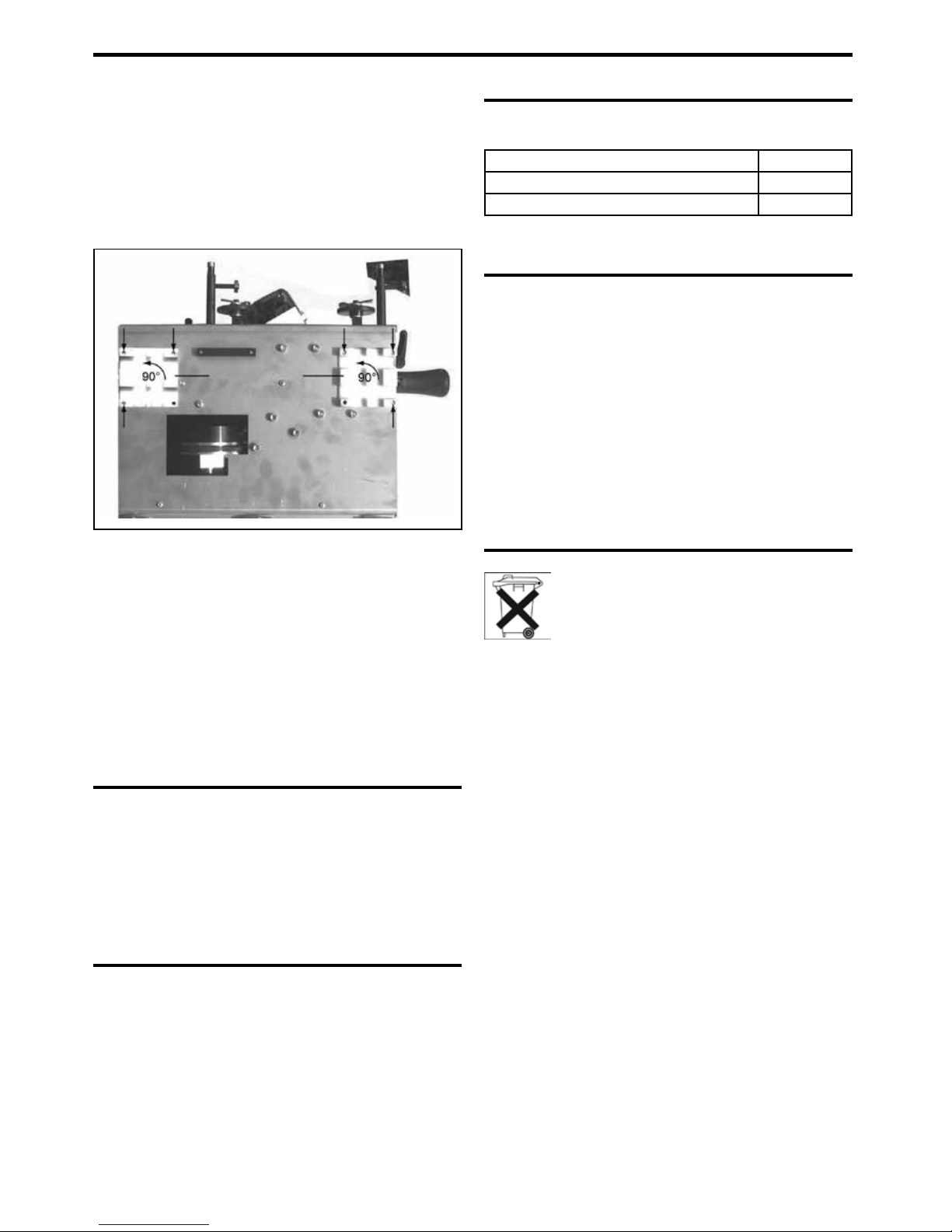
3.4 HANDLING DURING OPERATION
3.4.1 Operation with guide rails
Illustration 3.4.1/1: Guide rails with mounted clamping
arms (view from below)
To use the stapler with guide rails, carry out the following
steps:
1. First, mount the supplied limit stops on the guide rails.
Thexedlimitstop(ontherightinillustration3.4.1/1)
isxedusingelasticity.Pushthetensilelimitstopinto
the guide rails in such a way that it lies in the joint of the
panel to be processed.