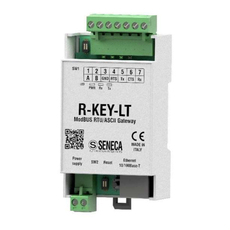
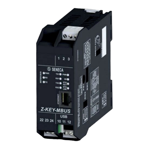
Seneca Z-KEY MBUS User manual

User Manual
Z-KEY-MBUS
R-KEY-MBUS
ALL RIGHTS RESERVED. NO PART OF THIS PUBLICATION MAY
BE REPRODUCED WITHOUT PRIOR PERMISSION.
www.seneca.it
Doc: MI-00592-IT
Rev. 1
Page 2
Introduction
The content of this documentation refers to products and technologies described in it.
All technical data contained in the document may be changed without notice.
The content of this documentation is subject to periodic review.
To use the product safely and effectively, read the following instructions carefully before use.
The product must be used only for the use for which it was designed and manufactured: any other use is under
the full responsibility of the user.
Installation, programming and set-up are allowed only to authorized, physically and intellectually suitable
operators.
Set-up must be performed only after correct installation and the user must follow all the operations described in
the installation manual carefully.
Seneca is not responsible for failures, breakages and accidents caused by ignorance or failure to apply the
stated requirements.
Seneca is not responsible for any unauthorized modifications.
Seneca reserves the right to modify the device, for any commercial or construction requirement, without the
obligation to promptly update the reference manuals.
No liability for the contents of this document can be accepted.
Use the concepts, examples and other content at your own risk.
There may be errors and inaccuracies in this document that could damage your system, so proceed with caution,
the author(s) will not take responsibility for it.
Technical specifications are subject to change without notice.
CONTACT US
Technical support
Product information

User Manual
Z-KEY-MBUS
R-KEY-MBUS
ALL RIGHTS RESERVED. NO PART OF THIS PUBLICATION MAY
BE REPRODUCED WITHOUT PRIOR PERMISSION.
www.seneca.it
Doc: MI-00592-IT
Rev. 1
Page 3
Document revisions
DATE
REVISION
NOTES
AUTHOR
05/09/2022
0
First revision
Aligned with firmware 109 revision
MM
13/03/2023
1
Aligned the chapter “MAPPING OF THE TAG AREA (HOLDING REGISTERS)”
with the firmware 110 revision.
MM
This document is the property of SENECA srl.
Copies and reproduction are prohibited unless authorised.

User Manual
Z-KEY-MBUS
R-KEY-MBUS
ALL RIGHTS RESERVED. NO PART OF THIS PUBLICATION MAY
BE REPRODUCED WITHOUT PRIOR PERMISSION.
www.seneca.it
Doc: MI-00592-IT
Rev. 1
Page 4
TABLE OF CONTENTS
INTRODUCTION...........................................................................................................5
DESCRIPTION..........................................................................................................................................................................5
COMMUNICATION PORT SPECIFICATIONS.........................................................................................................................7
APPLICATION FIELDS ................................................................................................8
CONNECTION WITH A PLC ....................................................................................................................................................8
CONNECTION WITH A SCADA ..............................................................................................................................................9
ETHERNET PORT......................................................................................................10
STEP BY STEP GUIDE FOR THE FIRST ACCESS TO THE WEBSERVER ............10
WEBSERVER DEVICE CONFIGURATION................................................................12
ACCESS TO THE WEB SERVER..........................................................................................................................................12
WEBSERVER SECTIONS......................................................................................................................................................13
“STATUS” SECTION .............................................................................................................................................................14
“SETUP” SECTION................................................................................................................................................................15
SAVING A CONFIGURATION ON A FILE.........................................................................................................................17
IMPORTING A CONFIGURATION FROM A FILE.............................................................................................................18
“M-BUS DEVICES” SECTION ...............................................................................................................................................19
REPLACEMENT OF AN M-BUS DEVICE .........................................................................................................................19
MANUAL ADDITION OF AN M-BUS DEVICE ...................................................................................................................20
“SCAN M-BUS” SECTION.....................................................................................................................................................21
SCANNING THE M-BUS....................................................................................................................................................21
ADDITION OF AN M-BUS DEVICE AND YOUR TAGS ....................................................................................................22
"TAG SETUP" SECTION .......................................................................................................................................................23
“UPDATE” SECTION.............................................................................................................................................................23
FIRMWARE UPDATE ........................................................................................................................................................24
DATABASE UPDATE.........................................................................................................................................................24
SUPPORTED MODBUS COMMUNICATION PROTOCOLS .....................................24
SUPPORTED MODBUS FUNCTION CODES........................................................................................................................24
MODBUS REGISTER MAPPING ...............................................................................25
MAPPING OF THE TAG AREA (HOLDING REGISTERS)....................................................................................................26
MAPPING OF THE DIAGNOSTIC AREA (HOLDING REGISTERS).....................................................................................29
RESETTING TO FACTORY CONFIGURATION ........................................................30
User Manual
Z-KEY-MBUS
R-KEY-MBUS
ALL RIGHTS RESERVED. NO PART OF THIS PUBLICATION MAY
BE REPRODUCED WITHOUT PRIOR PERMISSION.
www.seneca.it
Doc: MI-00592-IT
Rev. 1
Page 5
INTRODUCTION
ATTENTION!
This user manual extends the information from the installation manual to the configuration of the
device. Use the installation manual for more information.
ATTENTION!
In any case, SENECA s.r.l. or its suppliers will not be responsible for the loss of data/revenue or
consequential or incidental damages due to negligence or bad/improper management of the device,
even if SENECA is well aware of these possible damages.
SENECA, its subsidiaries, affiliates, group companies, suppliers and distributors do not guarantee that
the functions fully meet the customer's expectations or that the device, firmware and software should
have no errors or operate continuously.
ATTENTION!
Button PS1 is not used at the moment in the Z-KEY-MBUS instrument.
DESCRIPTION
The Z-KEY-MBUS / R-KEY-MBUS products autonomously read the registers of the devices on the Meter Bus
(M-BUS) and make them available for access via the serial ports, the USB port (Z-KEY-MBUS only) or via the
ethernet port using the Modbus RTU or Modbus TCP-IP protocols (Holding Register-type registers).
Seneca devices can be connected to a maximum of 25 M-BUS devices and can manage up to 500 M-BUS
variables (tags) (since an M-BUS variable can occupy up to 2 Modbus registers, the device makes available up
to 1000 Modbus registers (to which 32 Modbus diagnostic registers must be added).
To configure the device, the integrated webserver can be used without the need for external software.

User Manual
Z-KEY-MBUS
R-KEY-MBUS
ALL RIGHTS RESERVED. NO PART OF THIS PUBLICATION MAY
BE REPRODUCED WITHOUT PRIOR PERMISSION.
www.seneca.it
Doc: MI-00592-IT
Rev. 1
Page 6
Below are the connection configurations working simultaneously for both models:

User Manual
Z-KEY-MBUS
R-KEY-MBUS
ALL RIGHTS RESERVED. NO PART OF THIS PUBLICATION MAY
BE REPRODUCED WITHOUT PRIOR PERMISSION.
www.seneca.it
Doc: MI-00592-IT
Rev. 1
Page 7
COMMUNICATION PORT SPECIFICATIONS
ETHERNET COMMUNICATION PORT
Type
Ethernet 100 baseT RJ45 front
Configuration
Through integrated Webserver
Industrial communication protocol
Modbus TCP-IP server (max 8 simultaneous clients)
Ethernet device search
Through Seneca Discovery software
Factory address
Static address 192.168.90.101
RS485/RS232 SERIAL COMMUNICATION PORTS (Z-KEY-MBUS ONLY)
Number of ports
2
Type
COM#1 RS485 port for IDC10 connector
Terminal COM#2 RS485/RS232 port
Baud Rate
From 1200 to 115200 bit/s
Protocol
Modbus RTU Slave
RS485/RS232 SERIAL COMMUNICATION PORTS (R-KEY-MBUS ONLY)
Number of ports
1
Type
Terminal RS485/RS232 port
Baud Rate
From 1200 to 115200 bit/s
Protocol
Modbus RTU Slave
USB COMMUNICATION PORT (Z-KEY-MBUS ONLY)
Number of ports
1
Type
Driver Windows/Linux Virtual Com CDC standard
Protocol
Modbus RTU Slave
Configuration
Not modifiable 38400 bit/s, 8 bits, No parity, 1 stop bit, station
address 1
METER BUS COMMUNICATION PORT
Number of ports
1
Number of maximum Slave MBUS
25
Baud Rate
From 300 to 38400 bit/s

User Manual
Z-KEY-MBUS
R-KEY-MBUS
ALL RIGHTS RESERVED. NO PART OF THIS PUBLICATION MAY
BE REPRODUCED WITHOUT PRIOR PERMISSION.
www.seneca.it
Doc: MI-00592-IT
Rev. 1
Page 8
APPLICATION FIELDS
CONNECTION WITH A PLC
The most classic sphere of application is the Z/ R-KEY-MBUS connection with a PLC, in this case it is sufficient
for the PLC to support one of the following protocols:
▪MODBUS RTU Master (via RS232 or RS485)
▪MODBUS TCP-IP Client (via Ethernet)
The following example is related to Z-KEY-MBUS but is interchangeable with R-KEY-MBUS:

User Manual
Z-KEY-MBUS
R-KEY-MBUS
ALL RIGHTS RESERVED. NO PART OF THIS PUBLICATION MAY
BE REPRODUCED WITHOUT PRIOR PERMISSION.
www.seneca.it
Doc: MI-00592-IT
Rev. 1
Page 9
CONNECTION WITH A SCADA
To connect a SCADA to the Z/ R-KEY-MBUS gateway, the SCADA must support at least one of the following
protocols:
▪MODBUS RTU Master (via RS232 or RS485)
▪MODBUS TCP-IP Client (via Ethernet)
Practically all SCADAs support these protocols.
Virtually there are no limits to the number of Z/ R-KEY-MBUS gateways that can be connected to a SCADA:

User Manual
Z-KEY-MBUS
R-KEY-MBUS
ALL RIGHTS RESERVED. NO PART OF THIS PUBLICATION MAY
BE REPRODUCED WITHOUT PRIOR PERMISSION.
www.seneca.it
Doc: MI-00592-IT
Rev. 1
Page 10
ETHERNET PORT
The factory configuration of the Ethernet port is:
STATIC IP: 192.168.90.101
SUBNET MASK: 255.255.0.0
GATEWAY: 192.168.90.1
Multiple devices must not be inserted on the same network with the same static IP.
If you want to connect multiple devices on the same network, you need to change the IP address configuration
using the Webserver or the Seneca Discovery software.
ATTENTION!
DO NOT CONNECT 2 OR MORE FACTORY-CONFIGURED DEVICES ON THE SAME ETHERNET
NETWORK, OR THE DEVICE WILL NOT WORK (192.168.90.101 IP ADDRESS CONFLICT)
If the addressing mode with DHCP is activated and an IP address is not received within 2 minutes, the device
will set an error IP address such as:
169.254.x.y
Where x.y are the last two values of the MAC ADDRESS.
STEP BY STEP GUIDE FOR THE FIRST ACCESS TO THE WEBSERVER
STEP 1: POWER AND CONNECT THE ETHERNET PORT
STEP 2: SENECA DISCOVERY DEVICE SOFTWARE INSTALLATION
Download (from the Seneca website in the Z/R-KEY-MBUS section) the Seneca Discovery Device software.
STEP 3: SEARCH FOR THE DEVICE
Run the software and press the “SCAN” button: the software will search for the Ethernet devices in the network.
Locate the Z/R-KEY-MBUS device (factory default address 192.168.90.101):

User Manual
Z-KEY-MBUS
R-KEY-MBUS
ALL RIGHTS RESERVED. NO PART OF THIS PUBLICATION MAY
BE REPRODUCED WITHOUT PRIOR PERMISSION.
www.seneca.it
Doc: MI-00592-IT
Rev. 1
Page 11
The software works at Ethernet Layer 2 level and it is therefore not necessary to have an Ethernet configuration
compatible with the device you are looking for.
STEP 4 CHANGE OF IP ADDRESS
Select the device and press the “Assign IP” button, set a configuration compatible with your PC, for instance:
Confirm with OK. Now the device can be reached via Ethernet from your PC.
STEP 5 ACCESS TO THE CONFIGURATION WEBSERVER
Wait for the device to restart and press the “Open Webserver” button.
ENTER your access credentials:
user: admin
password: admin
ATTENTION!
THE WEB BROWSERS WHICH HAVE BEEN TESTED FOR COMPATIBILITY WITH THE DEVICE
WEBSERVER ARE:
MOZILLA FIREFOX AND GOOGLE CHROME.
THEREFORE, THE OPERATION WITH OTHER BROWSERS IS NOT GUARANTEED

User Manual
Z-KEY-MBUS
R-KEY-MBUS
ALL RIGHTS RESERVED. NO PART OF THIS PUBLICATION MAY
BE REPRODUCED WITHOUT PRIOR PERMISSION.
www.seneca.it
Doc: MI-00592-IT
Rev. 1
Page 12
WEBSERVER DEVICE CONFIGURATION
For further information on the access to the webserver of a new device, please refer to chapter 4.
ATTENTION!
THE WEB BROWSERS WHICH HAVE BEEN TESTED FOR COMPATIBILITY WITH THE DEVICE
WEBSERVER ARE:
MOZILLA FIREFOX AND GOOGLE CHROME.
THEREFORE, THE OPERATION WITH OTHER BROWSERS IS NOT GUARANTEED
ACCESS TO THE WEB SERVER
Access to the web server takes place using a web browser and entering the IP address of the device.
To find out the IP address of the device, use the "search" function of the "Seneca Discovery Device" software
(see chapter 4).
On first access the user name and password will be requested.
The default values are:
Username: admin Password: admin
ATTENTION!
AFTER THE FIRST ACCESS CHANGE USER NAME AND PASSWORD IN ORDER TO PREVENT
ACCESS TO THE DEVICE TO UNAUTHORIZED PEOPLE.
ATTENTION!
IF THE PARAMETERS TO ACCESS THE WEBSERVER HAVE BEEN LOST, TO ACCESS IT, IT IS
NECESSARY TO GO THROUGH THE PROCEDURE TO RESET THE FACTORY-SET CONFIGURATION

User Manual
Z-KEY-MBUS
R-KEY-MBUS
ALL RIGHTS RESERVED. NO PART OF THIS PUBLICATION MAY
BE REPRODUCED WITHOUT PRIOR PERMISSION.
www.seneca.it
Doc: MI-00592-IT
Rev. 1
Page 13
WEBSERVER SECTIONS
The Webserver is divided into pages (sections) representing the various gateway functions:
Status
It is the section that displays the values of the configured tags in real time.
Setup
It is the section that allows the device basic configuration.
M-Bus Devices
It is the section that allows adding/modifying the M-bus devices connected to the gateway.
Scan M-Bus
It is the section that allows scanning and automatically adding the M-bus devices to the gateway.
Setup Tag
It is the section that allows adding/modifying the tags (that is the variables) of the M-bus devices connected to
the gateway.
Update
It is the section that allows updating the firmware and database for the manual addition of the M-BUS meters.

User Manual
Z-KEY-MBUS
R-KEY-MBUS
ALL RIGHTS RESERVED. NO PART OF THIS PUBLICATION MAY
BE REPRODUCED WITHOUT PRIOR PERMISSION.
www.seneca.it
Doc: MI-00592-IT
Rev. 1
Page 14
“STATUS” SECTION
In the status section, it is possible to view the tag values in real time together with their fail/ok status:
50 tags per page maximum can be displayed, the maximum number of pages is 10.
Some basic information among which the device interrogation loop time is displayed in the top part of the
page.

User Manual
Z-KEY-MBUS
R-KEY-MBUS
ALL RIGHTS RESERVED. NO PART OF THIS PUBLICATION MAY
BE REPRODUCED WITHOUT PRIOR PERMISSION.
www.seneca.it
Doc: MI-00592-IT
Rev. 1
Page 15
“SETUP” SECTION
DHCP (ETH) (default: Disabled)
Sets the DHCP client to get an IP address automatically.
STATIC IP (default: 192.168.90.101)
Sets the device static address. Careful not to enter devices with the same IP address into the same network.
STATIC IP MASK (default: 255.255.255.0)
Sets the mask for the IP network.
STATIC GATEWAY (default: 192.168.90.1)
Sets the gateway address.
RESPONSE MODE WHEN RESOURCE IN FAIL (default: EXCEPTION)
Selects what answer to give if the M-BUS meter connected does not answer the requests. It is possible to choose
between:

User Manual
Z-KEY-MBUS
R-KEY-MBUS
ALL RIGHTS RESERVED. NO PART OF THIS PUBLICATION MAY
BE REPRODUCED WITHOUT PRIOR PERMISSION.
www.seneca.it
Doc: MI-00592-IT
Rev. 1
Page 16
Exception: The response to the modbus request of the tag in fail will be an exception.
Last Value Read: The response to the modbus request of the tag in fail will the last valid value.
Max: The response to the tag modbus request will be the maximum value that can be represented by the type
of data.
Min: The response to the tag modbus request will be the minimum value that can be represented by the type of
data.
Zero: The response to the tag modbus request will be 0.
TCP-IP PORT (default: 502)
Sets the communication port for the Modbus TCP-IP server protocol.
MBUS TIMEOUT [ms] (default 10000 ms)
Sets the waiting time for a request to be considered in timeout.
MBUS CYCLE PAUSE [s] (default 5 s)
Sets the waiting time after completing a round of requests on all M-BUS devices.
MBUS READING RETRIES (default 3)
Sets the number of request retries before considering a tag in fail.
WEB SERVER AUTHENTICATION USER NAME (default: admin)
Sets the username to access the webserver.
WEB SERVER PASSWORD (default: admin)
Sets the password to access the webserver and to read/write the configuration (if enabled).
WEB SERVER PORT (default: 80)
Sets the communication port for the web server.
IP CHANGE FROM DISCOVERY (default: Enabled)
Selects whether or not the device accepts the IP address change from the Seneca Discovery Device software.
PORT #1 SLAVE MODBUS ADDRESS (default: 1)
Selects the Modbus slave station address of COM #1 port (on IDC10 connector for Z-KEY-MBUS, on terminal
for R-KEY-MBUS).
PORT #1 BAUDRATE (default: 38400 baud)
Selects the communication speed of COM #1 serial port (on IDC10 connector for Z-KEY-MBUS, on terminal for
R-KEY-MBUS).

User Manual
Z-KEY-MBUS
R-KEY-MBUS
ALL RIGHTS RESERVED. NO PART OF THIS PUBLICATION MAY
BE REPRODUCED WITHOUT PRIOR PERMISSION.
www.seneca.it
Doc: MI-00592-IT
Rev. 1
Page 17
PORT #1 PARITY (default: None)
Selects the parity for the COM #1 serial communication port (on IDC10 connector for Z-KEY-MBUS, on terminal
for R-KEY-MBUS).
PORT #1 STOP BIT (default: 1)
Sets the number of stop bits for the COM #1 serial communication port (on IDC10 connector for Z-KEY-MBUS,
on terminal for R-KEY-MBUS).
PORT #2 SLAVE MODBUS ADDRESS (default: 1) (Z-KEY-MBUS ONLY)
Selects the Modbus slave station address of the COM #2 port (on terminal).
PORT #2BAUDRATE (default: 38400 baud) (Z-KEY-MBUS ONLY)
Selects the communication speed of the COM #2 serial port (on terminal)
PORT #2 PARITY (default: None) (Z-KEY-MBUS ONLY)
Sets the parity for the COM #2 serial communication port (on terminal).
PORT #2 STOP BIT (default: 1) (Z-KEY-MBUS ONLY)
Sets the number of stop bits for the COM #2 serial communication port (on terminal).
In addition, a configuration can be exported / imported via the webserver.
SAVING A CONFIGURATION ON A FILE
A configuration that includes:
CONFIGURATION
M-BUS DEVICE
TAG
It can be saved to a file this way:
Go to the Setup section and select the file to save, press the "Save config" button

User Manual
Z-KEY-MBUS
R-KEY-MBUS
ALL RIGHTS RESERVED. NO PART OF THIS PUBLICATION MAY
BE REPRODUCED WITHOUT PRIOR PERMISSION.
www.seneca.it
Doc: MI-00592-IT
Rev. 1
Page 18
IMPORTING A CONFIGURATION FROM A FILE
A configuration that includes:
CONFIGURATION
M-BUS DEVICE
TAG
It can be imported from a file this way:
Go to the Update section and select the file to load, press the "Load config" button

User Manual
Z-KEY-MBUS
R-KEY-MBUS
ALL RIGHTS RESERVED. NO PART OF THIS PUBLICATION MAY
BE REPRODUCED WITHOUT PRIOR PERMISSION.
www.seneca.it
Doc: MI-00592-IT
Rev. 1
Page 19
“M-BUS DEVICES” SECTION
This section shows the M-BUS devices inserted in the gateway.
It is possible to delete all the tags related to a device by deleting the device from the list of devices.
REPLACEMENT OF AN M-BUS DEVICE
It is also possible to change the address (for example in case of replacement) using the "MODIFY" button:

User Manual
Z-KEY-MBUS
R-KEY-MBUS
ALL RIGHTS RESERVED. NO PART OF THIS PUBLICATION MAY
BE REPRODUCED WITHOUT PRIOR PERMISSION.
www.seneca.it
Doc: MI-00592-IT
Rev. 1
Page 20
MANUAL ADDITION OF AN M-BUS DEVICE
By means of the "ADD" button, instead, it is possible to access the addition of an M-BUS device in manual
mode. Z/R-KEY-MBUS has a database growing continuously with the devices of the main brands.
A = Select the brand of the device to insert
A = Select the model of the device to insert
C = Select if the device must be interrogated via primary or secondary address
D = Device address
E = Device Baud rate
If you only want to insert the device without the tags, press the "APPLY WITHOUT DATA POINTS
SELECTED" button
If you only want to insert both the device and the selected tags, press the "APPLY WITH DATA POINTS
SELECTED" button
This manual suits for next models
1
Table of contents
Other Seneca Gateway manuals

Seneca
Seneca R-KEY-LT User manual

Seneca
Seneca Z-KEY User manual

Seneca
Seneca Z-LINK2-LO User manual

Seneca
Seneca Z-KEY-2ETH-P User manual

Seneca
Seneca Z-GW-MB User manual

Seneca
Seneca X-HDU Instruction Manual

Seneca
Seneca Z-KEY User manual

Seneca
Seneca R-KEY-LT User manual

Seneca
Seneca Z-KEY-MBUS User manual

Seneca
Seneca R-KEY-LT User manual

Seneca
Seneca Z-PC SERIES User manual

Seneca
Seneca Z-KEY User manual

Seneca
Seneca Z-PASS2 User manual

Seneca
Seneca Z-PASS1-R02 User manual

Seneca
Seneca Z-KEY-P User manual

Seneca
Seneca R-KEY-LT User manual

Seneca
Seneca R-PASS User manual

Seneca
Seneca Z-KEY User manual

Seneca
Seneca Z-KEY-P User manual

Seneca
Seneca Z-KEY-2ETH-P User manual