Seneca Z-GW-MB User manual

User Manual Modbus TCP Server / Modbus RTU
Master
Document code: MI002260-E
Automation instruments and solutions
Z-GW-MB
Seneca Srl – IT - 35133 – Z.I. Camin – Padova INFO http //www.seneca.it/ Phone +39.049.87.05.(359) /(408)
User Manual
English
Gateway / Bridge
Modbus TCP Server to Modbus RTU Master
(Order Code: Z- W-MB)
for Website information:
www.seneca.it
for Technical information:
http://www.seneca.it/prodotti.php
Or send an email to:
Benefits and Main Features:
Very easy to configure
Low Cost
Rail mountable
Wide supply input range
alvanic Isolation
Industrial temperature range:
-20°C / 70 °C

User Manual Modbus TCP Server / Modbus RTU
Master
Document code: MI002260-E
Automation instruments and solutions
IN EX:
Page
INDEX 2
CHARACTERISTICS 3
POWER SUPPLY 3
FUNTION SCHEME 4
CONNECTION SCHEME 5
USE OF COMPOSITOR SW67507 6
NEW PROJECT / OPEN PROJECT 6
ENERAL PARAMETER 7
PIN DEVICE 8
OPERATIONAL MODE: ROUTIN 8
OPERATIONAL MODE: NATTIN 9
TRANSLATE TABLE 9
UPDATE VIA TCP 11
UPDATE VIA SERIAL 12
CHARACTERISTICS OF THE CABLES 13
DETAILS ABOUT THE ETHERNET CABLE 13
MECHANICAL DIMENSIONS 13
ORDER CODE 14
ACCESSORIES 14
WARRANTIES AND TECHNICAL SUPPORT 14
RETURN POLICY 14
PRODUCTS AND RELATED DOCUMENTS 14
Seneca Srl – IT - 35133 – Z.I. Camin – Padova INFO http //www.seneca.it/ Phone +39.049.87.05.(359) /(408)

User Manual Modbus TCP Server / Modbus RTU
Master
Document code: MI002260-E
Automation instruments and solutions
CHARACTERISTICS:
The Modbus TCP to Modbus RTU ateway allows the following characteristics:
Opto-isolation RS485;
Choice possibility between RS232 or RS485;
Mountable on Rail DIN;
Temperature range -20°C to 70°C;
EMS EN 61000-6-2.
This device is able to manage a maximum of ten simultaneous connections from Ethernet side.
To configure the ateway, use the available software that runs with Windows, called SW67507. It is downloadable on the site www.seneca.it
and its operation is described in this document.
It can be used in two operative ways: routing and natting. In the “Routing Mode” the command Modbus is forwarded on the serial line using
the same requested addresses. In the “Natting Mode” the device addresses and data are altered through a translation table of the
addresses.
POWER SUPPLY:
Recommended power supply
V dc V ac
24 V 12 V
Vdc Vac
V min V max V min V max
12 V 40 V 12 V 28 V
Seneca Srl – IT - 35133 – Z.I. Camin – Padova INFO http //www.seneca.it/ Phone +39.049.87.05.(359) /(408)

User Manual Modbus TCP Server / Modbus RTU
Master
Document code: MI002260-E
Automation instruments and solutions
FUNCTION SCHEME:
Figure 1 Connection scheme of Z-GW-MB between Modbus TCP and Modbus RTU (communication RS485)
Figure 2 Connection scheme of Z-GW-MB between Modbus TCP and Modbus RTU (communication RS232)
Seneca Srl – IT - 35133 – Z.I. Camin – Padova INFO http //www.seneca.it/ Phone +39.049.87.05.(359) /(408)

User Manual Modbus TCP Server / Modbus RTU
Master
Document code: MI002260-E
Automation instruments and solutions
USE OF COMPOSITOR SW67507:
The software allows the device parameters to be
defined.
When launching the SW67507, the following window
appears.
(The SW67507 is downloadable on the site
www.seneca.it
This manual is referenced to the last version of the
software present on our web site)
NEW PROJECT / OPEN PROJECT:
The “New Project” button creates the folder which contains the entire device configuration.
A device configuration can also be imported or exported:
To clone the configurations of a Programmable ModBus RTU into Modbus TCP ateway in order to configure another device in the
same manner, it is necessary to maintain the folder and all its contents;
To clone a project in order to obtain a different version of the project, it is sufficient to duplicate the project folder with another name
and open the new folder with the button “Open Project”;
When a new project is created or an existent project is open, it will be possible to access the various configuration sections of the
Software:
o“General Parameter”;
o“Translate Table”.
Seneca Srl – IT - 35133 – Z.I. Camin – Padova INFO http //www.seneca.it/ Phone +39.049.87.05.(359) /(408)
Figure 5 Main window for SW67507

User Manual Modbus TCP Server / Modbus RTU
Master
Document code: MI002260-E
Automation instruments and solutions
GENERAL PARAMETER:
This section defines the fundamental communication parameters
of two Buses, Modbus TCP and Modbus RTU.
By pressing the “ eneral Parameter” button from the main
window for SW67507 (Fig. 5) the window “ eneral Parameter”
appears (Fig. 6).
The field “Operation Mode” defines the operation of the
ateway in Routing or NAT modes (see the description in
the following page);
In the field “IP Address” insert the IP address that you
want to give to the slave Modbus TCP;
In the field “Subnet Mask” insert the Subnet Mask;
In field “ ateway” insert the Defualt ateway IP address
for use the gateway in WAN or Internet. For enable this
feature is necessary to check the ateway option.
In the field “Port” insert the number of port;
If the field “RS232” is checked the serial line in use is the
RS232, otherwise is the RS485;
In the field “Baud rate” the velocity of the Modbus RTU is
defined;
In the field “Parity” the Modbus RTU parity is defined;
“Timeout” is the maximum time that the device attends for
the answer from the Slave interrogated;
Checking “Enable UDP Port” field it is possible to make a Broadcast
request. This request must be made at Port 64223 ($FADF) with
these six byte of data: $53, $45, $41, $52, $43, $48. Each device
in response sends a total of 10 Bytes. These bytes are four for the
IP and the other for the MAC address (Example of response: 0xC0,
Seneca Srl – IT - 35133 – Z.I. Camin – Padova INFO http //www.seneca.it/ Phone +39.049.87.05.(359) /(408)
Figure 6 “General Parameter” window

User Manual Modbus TCP Server / Modbus RTU
Master
Document code: MI002260-E
Automation instruments and solutions
0xA8, 0x01, 0x2A, 0x11, 0x22, 0x33, 0x44, 0x55, 0x58. So the IP
is: 192.168.1.42; and the MAC Address: 11-22-33-44-55-58 ).
If the field “Enable Special Command” is checked, it is possible to send a no-Modbus request through the gateway. i.e. a TCP frame
with the first two caracters 0x55 and 0xAA is sent in the Modbus RTU line as is. If you don’t want to send the first two bytes (0x55,
0xAA) in the RTU line it is possible to check the field “Cancel the first two bytes”.
PING EVICE:
If it is necessary to do a Ping on the net, before pressing the “Ping Device” button insert a value in the field on the right and then press the
button. In order to do this, the gateway must be in RUN mode. To use this feature in Vista and 7 you have to open the software with Admin-
istrator right.
OPERATIONAL MO E:
ROUTING:
A few characteristics of the Modbus RTU package have been modified in the standard of the Modbus TCP protocol. Two bytes of the final CRC
were eliminated (no longer necessary for the information to reach its already corrected destination). The first byte of the slave identification
was changed, leaving the one that is called PDU. A frame denominated as MBAP header with dimensions of 7 bytes was added to the head of
the PDU.
It is composed by the following:
Word transaction identifier (recopied from the slave in the response phase);
Word protocol identifier (0=Modbus protocol);
Word length (number of successive bytes);
Byte unit identifier (used for the routing operation).
By using the last byte of the MBAP header, it is possible to carry out the routing from a requested Modbus TCP toward a serial line using the
address from the slave which is specified by the byte unit identifier.
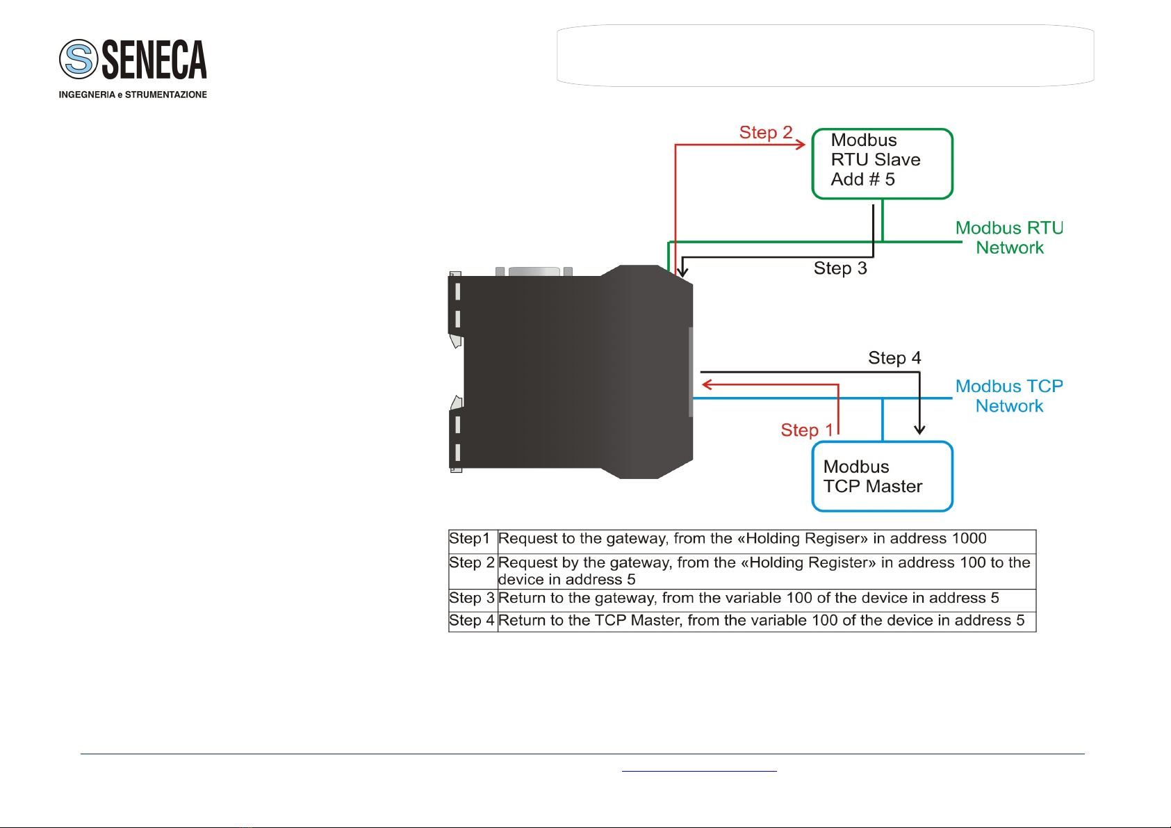
Example:
A requested Modbus TCP made in the device as the address 192.168.0.200 for the holding register address $2000, which is MBAP unit
identifier has the value of 2. It will be followed by the request on the serial for the device with the address 2 at the word $2000.
After the request is made, the RTU will respond. The master TCP will be given the same response which will be reconstructed according to
the specifications of the Modbus TCP.
If the RTU slave responds with an exception, that exception code will be transmitted again to the TCP master. If the RTU slave does not
respond in the estimated time defined by the Timeout parameter, an exception response will be given: error code $0B.
Seneca Srl – IT - 35133 – Z.I. Camin – Padova INFO http //www.seneca.it/ Phone +39.049.87.05.(359) /(408)

User Manual Modbus TCP Server / Modbus RTU
Master
Document code: MI002260-E
Automation instruments and solutions
NATTING:
When using the operation mode, Natting, the requested data will be processed through a table of translations of the Modbus network
addresses.
TRANSLATE TABLE:
Within the section “Translate Table” you can
define the variables that can be read or written
by the TCP bus on the RTU bus when the
device is in NAT mode.
By pressing the “Translate Table” button from
the main window for SW67507 (Fig. 5) the
window “Set Translate Table” appears (Fig. 7).
The data of the columns have the following meanings:
In the field “Data Type” insert the type of data that is being considered;
In the field “Address TCP” insert the virtual address of the present data in a device in the TCP Modbus;
In the field “Address Device RTU” insert the address of the device on the RTU Modbus that contains the data;
In the field “Address RTU” insert the address of the data on the RTU device;
In the field “N° Point” insert the number of consecutive data that you want to configure. For example, you create Address TCP=1000,
Address RTU=100 and N° point = 5, the following gets set-up automatically: addresses TCP 1001, 1002, 1003, 1004 and the variables
RTU 101, 102, 103, 104;
In the field “Mnemonic” you can insert a brief description.
Seneca Srl – IT - 35133 – Z.I. Camin – Padova INFO http //www.seneca.it/ Phone +39.049.87.05.(359) /(408)
Figure 7 “Set Translate Table”
window

User Manual Modbus TCP Server / Modbus RTU
Master
Document code: MI002260-E
Automation instruments and solutions
Example 1:
If you want, from TCP network, write a data
it the RTU network on the device at:
Address 5;
Through ateway WORD 100
(Address RTU);
Address TCP 1000.
In the above scenario:
Specify the type of data between:
Holding Register (word in read
and write);
Input Register (word in read).
From the side of the MODBUS TCP:
Address of data to read.
From the side of the MODBUS RTU:
Address of the device to inter
rogate;
Address of data to read on
device.
If the RTU slave responds with an exception, that exception code will be transmitted to the TCP Master. If the RTU slave does not respond
within the estimated time defined by the Timeout parameter, an exception response will be given: error code $0B.
Seneca Srl – IT - 35133 – Z.I. Camin – Padova INFO http //www.seneca.it/ Phone +39.049.87.05.(359) /(408)
Figure 8 Chart of Request data from Modbus TCP

User Manual Modbus TCP Server / Modbus RTU
Master
Document code: MI002260-E
Automation instruments and solutions
UP ATE VIA TCP:
Section “Update Via TCP” (Fig. 9):
In order to load the parameters or update the firmware in the
ateway, follow these instructions:
Connect the Ethernet cable to the ateway;
Insert the IP address of the ateway;
Press the “Ping” button for check the connection of the ateway;
Press the “Next” button;
Select the operations you want to do. You can select only “Firmware”, only “Project” or
both of them;
Press the “Execute update firmware” button to start the upload.
When all the operations are “OK” the configuration/firmware on the device is
correctly updated.
To use this feature in Vista and 7 you have to open the software with Administrator right.
Seneca Srl – IT - 35133 – Z.I. Camin – Padova INFO http //www.seneca.it/ Phone +39.049.87.05.(359) /(408)
Figure 9 “Update Via TCP” windows

User Manual Modbus TCP Server / Modbus RTU
Master
Document code: MI002260-E
Automation instruments and solutions
UPDATE IA SERIAL
Section “Update Via Serial” (Fig. 10):
In order to load the parameters or update the firmware in the ateway,
follow these instructions:
Turn OFF the device;
Connect the Null Modem cable from your PC to the ateway;
Insert the Boot Jumper (For more info see the “Connection scheme” of
the ateway);
Turn ON the device;
Check the “BOOT Led”. It must blink quickly (more info see the
“Connection scheme” of the ateway);
Select the COM port and press the “Connect” button;
Press the “Next” button;
Select the operations you want to do. You can select only “Firmware”,
only “Project” or both of them;
Press the “Execute update firmware” button to start the upload;
When all the operations are “OK” turn OFF the device;
Disconnect the Boot Jumper;
Turn ON the device.
At this point the configuration/firmware on the device is correctly updated.
Seneca Srl – IT - 35133 – Z.I. Camin – Padova INFO http //www.seneca.it/ Phone +39.049.87.05.(359) /(408)
Figure 10 “Update Via Serial” windows

User Manual Modbus TCP Server / Modbus RTU
Master
Document code: MI002260-E
Automation instruments and solutions
CHARACTERISTICS OF THE CABLES:
The connection from RS232 socket to a serial port (example one from a personal computer) must be made with a pin-to-pin cable (a serial
cable where the pins 2 and 3 are NOT crossed).
It is recommended that the RS232C Cable not exceed 3 meters.
ETAILS ABOUT THE ETHERNET CABLE:
Linking of Ethernet connector to a HUB must be carried out by a Category 5E cable. The cable has to conform to the T568 norms relative to
connections in cat.5 up to 100 Mbps. The length cannot go beyond 100 meters.
MECHANICAL IMENSIONS:
Seneca Srl – IT - 35133 – Z.I. Camin – Padova INFO http //www.seneca.it/ Phone +39.049.87.05.(359) /(408)
Figure 11 Mechanical dimensions scheme for Z-GW-MB

User Manual Modbus TCP Server / Modbus RTU
Master
Document code: MI002260-E
Automation instruments and solutions
OR ER CO E
Order Code: Z-GW-MB - ateway – Modbus TCP Server to Modbus RTU Master
ACCESSORIES:
OR ER CO E ESCRIPTION
Order Code: Z-PC-DINAL1-35 - DIN rail support with screw terminals P=35 mm
Order Code: Z-PC-DINAL2-17,5 - DIN rail support with screw terminals P=17,5 mm
Order Code: Z-PC-DIN1-35 - DIN 1 slot support for rear connector P=35 mm
Order Code: Z-PC-DIN2-17,5 - DIN 2 slot support for rear connector P=17,5 mm
Order Code: Z-PC-DIN4-35 - DIN 4 slot support for rear connector P=35 mm
Order Code: Z-PC-DIN8-17,5 - DIN 8 slot support for rear connector P=17,5 mm
Order Code: PM001450 - Ethernet cable 1,5 m
Order Code: PM002490 - RS232 cable (DB9M-DB9F), pin to pin
WARRANTIES AN TECHNICAL SUPPORT:
For fast and easy technical support for your Seneca srl products, consult our internet support at www.seneca.it
Otherwise contact us at the address [email protected]
RETURN POLICY:
If while using your product you have any problem and you wish to exchange or repair it, please do the following:
1) Obtain a Product Return Number (PRN) from our internet support at www.seneca.it together with the request, you need to provide detailed information about
the problem.
2) Send the product to the address provided with the PRN, having prepaid the shipping costs (shipment costs billed to us will not be accepted).
If the product is within the warranty of twelve months, it will be repaired or exchanged and returned within three weeks. If the product is no longer under warranty,
you will receive a repair estimate.
PRO UCTS AN RELATE OCUMENTS:
Part escription Other documentation
Z- W-MB ateway Modbus TCP Server to RTU Master MI002251-I-E from INSTALLATION MANUAL www.seneca.it
Seneca Srl – IT - 35133 – Z.I. Camin – Padova INFO http //www.seneca.it/ Phone +39.049.87.05.(359) /(408)
Other manuals for Z-GW-MB
1
Table of contents
Other Seneca Gateway manuals

Seneca
Seneca Z-PC SERIES User manual

Seneca
Seneca Z-KEY-P User manual

Seneca
Seneca Z-KEY User manual

Seneca
Seneca R-GWR User manual

Seneca
Seneca X-HDU Instruction Manual

Seneca
Seneca Z-PASS2 User manual

Seneca
Seneca R-KEY-LT User manual

Seneca
Seneca Z-KEY-MBUS User manual

Seneca
Seneca R-KEY-LT User manual

Seneca
Seneca R-KEY-LT User manual

Seneca
Seneca Z-KEY User manual

Seneca
Seneca Z-LINK2-LO User manual

Seneca
Seneca Z-PASS1-R02 User manual

Seneca
Seneca Z-KEY-2ETH-P User manual

Seneca
Seneca R-PASS User manual

Seneca
Seneca R-GWR User manual

Seneca
Seneca Z-KEY-MBUS User manual

Seneca
Seneca Z-KEY User manual

Seneca
Seneca Z-KEY User manual

Seneca
Seneca Z-PASS2-IO User manual