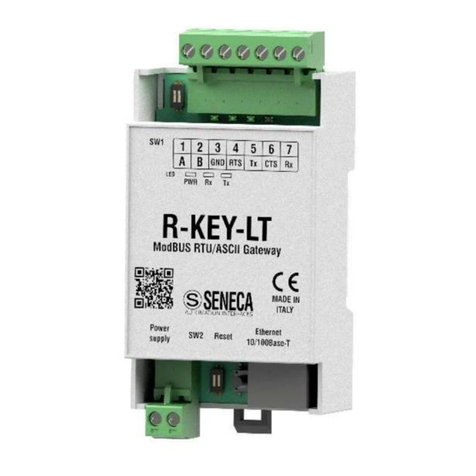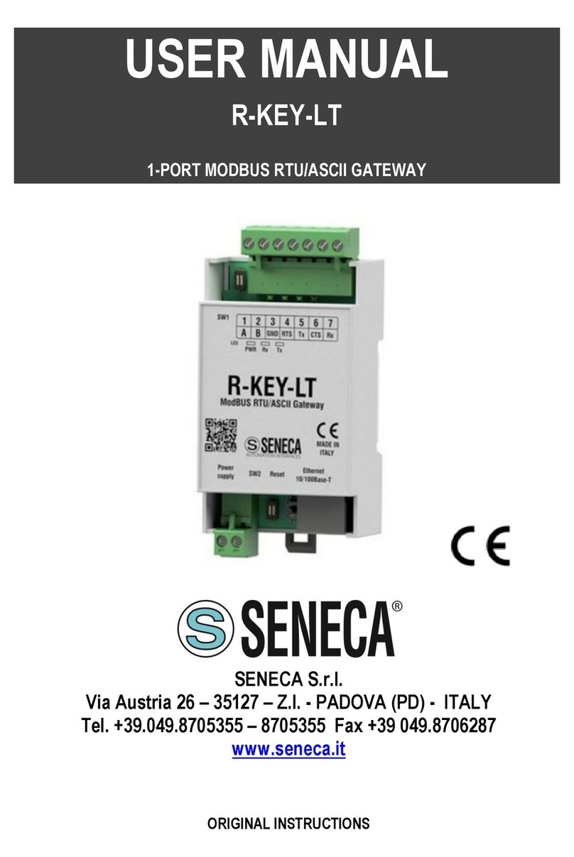
1-Port ModBUS RTU/ASCII Industrial Gateway
Doc. MI000472 Rev. 0 P a g e 5
SETTINGS
SW2 DIP-switch
device (*):
To obtain the configuration from the Flash
memory, both selectors of the SW" DIP
switch must be set to OFF
OFF OFF
To reset the device and revert to the factory
settings, both SW2 DIP switch selectors
must be set to ON
ON ON
To force the IP address of the device to the
standard value of the SENECA ethernet
products: 192.168.90.101
OFF ON
Reserved
ON OFF
(*) ATTENTION: the DIP-switch settings are read only during the boot
phase. Restart after every change.
Installation: Position the device on the
OMEGA rail, resting the top teeth from
top to bottom.
Push the bottom part towards the rail till
the locking system engages.
Removal: Switch the module off; using
a slotted screwdriver, release the
locking system.
Installation: The device is provided
with a hole for wall-mounting. Follow the
image on the side after preparing wall
block and relative screw.
Removal: Switch the module off; push
lightly upwards and get the product
away from the wall.
1-Port ModBUS RTU/ASCII Industrial Gateway
Doc. MI000472 Rev. 0 P a g e 6
TECHNICAL SPECIFICATIONS
Voltage
Absorption
10 40 Vdc; 19 28 Vac 50 60 Hz
Max: 1 W
CPU ARM 32 bit
INSULATION
OPERATING MODES
Gateway from Ethernet ModBUS to serial
Gateway from serial ModBUS to Ethernet
Traffic monitor function via webserver
1 switchable RS232 or RS485
on removable terminal (1-7)
ModBUS RTU ASCII Master / ModBUS RTU ASCII
Slave protocol
1 Ethernet on RJ45
ModBUS TCP-IP.
CONNECTIONS
7-way removable screw terminals, 5mm pitch (*)
2-way removable screw terminals, 5mm pitch (*)
RJ45 Ethernet connector on the bottom
(*) with 2.5mm² max cable section
CONFIGURATION Configuration and FW update via webserver;
DIP-switches
MOUNTING DIN rail bar IEC EN 60715 or wall mounting
AMBIENT CONDITIONS
Operating temperature
Humidity
Altitude
Storage temperature
Protection rating
-20°C +70°C
30 90% non condensing
up to 2.000 m above sea level
-20°C +85°C
IP20
STANDARDS
environment)
EN61000-6-2 (electromagnetic immunity, industrial
environment)
EN61010-1 (safety).
1-Port ModBUS RTU/ASCII Industrial Gateway
Doc. MI000472 Rev. 0 P a g e 7
Terminal for RS232 or RS485 switchable
serial port
To use COM RS485
The connections of the terminal are 1-
2-3, A(+), B(-) and GND respectively.
N.B. The indication of the RS485
connection polarity (terminals 1 and 2) is
not standardised and in some devices
may be inverted.
To use COM RS232
The connections of the terminal are 3-
4-5-6-7, GND, RTS, Tx, CTS and Rx
respectively.
The picture on the side, reproduced
partly on the product, shows the key of
the contacts.
N.B. see the paragraph SETTINGS on
page 4 in case of communication
problems.
Power supply
Electrical power connections are
available from terminals 8 and 9.
The power supply voltage must remain
in the range of either 10 and 40Vdc (any
polarity), or 19 and 28Vac.
The upper limits must not be
exceeded in order to avoid serious
damage to the module.
The power supply source must be
protected from any module malfunctions
using appropriately-sized safety fuses.
1-Port ModBUS RTU/ASCII Industrial Gateway
Doc. MI000472 Rev. 0 P a g e 8
Reboot button
The button is positioned between the
SW2 DIP-switch and the Ethernet
socket. To reboot the device, just press
the button and do not release it for 5
seconds. Release it when all the LEDs
are lit.
RJ45 Ethernet ports
The R-KEY-LT has an Ethernet 10/100
port with RJ45 connector in the lower
part of the module.
ACCESSORIES
CE-RJ45-RJ45-R 1,5 m long RJ45-RJ45 Ethernet cable
ALIM-MY2 230 V / 12V power supply (optional)
CONTACTS
Product information: sales@seneca.it
For further information, refer to the USER MANUAL that can be downloaded free of charge from
www.seneca.it/products/r-key-lite.
