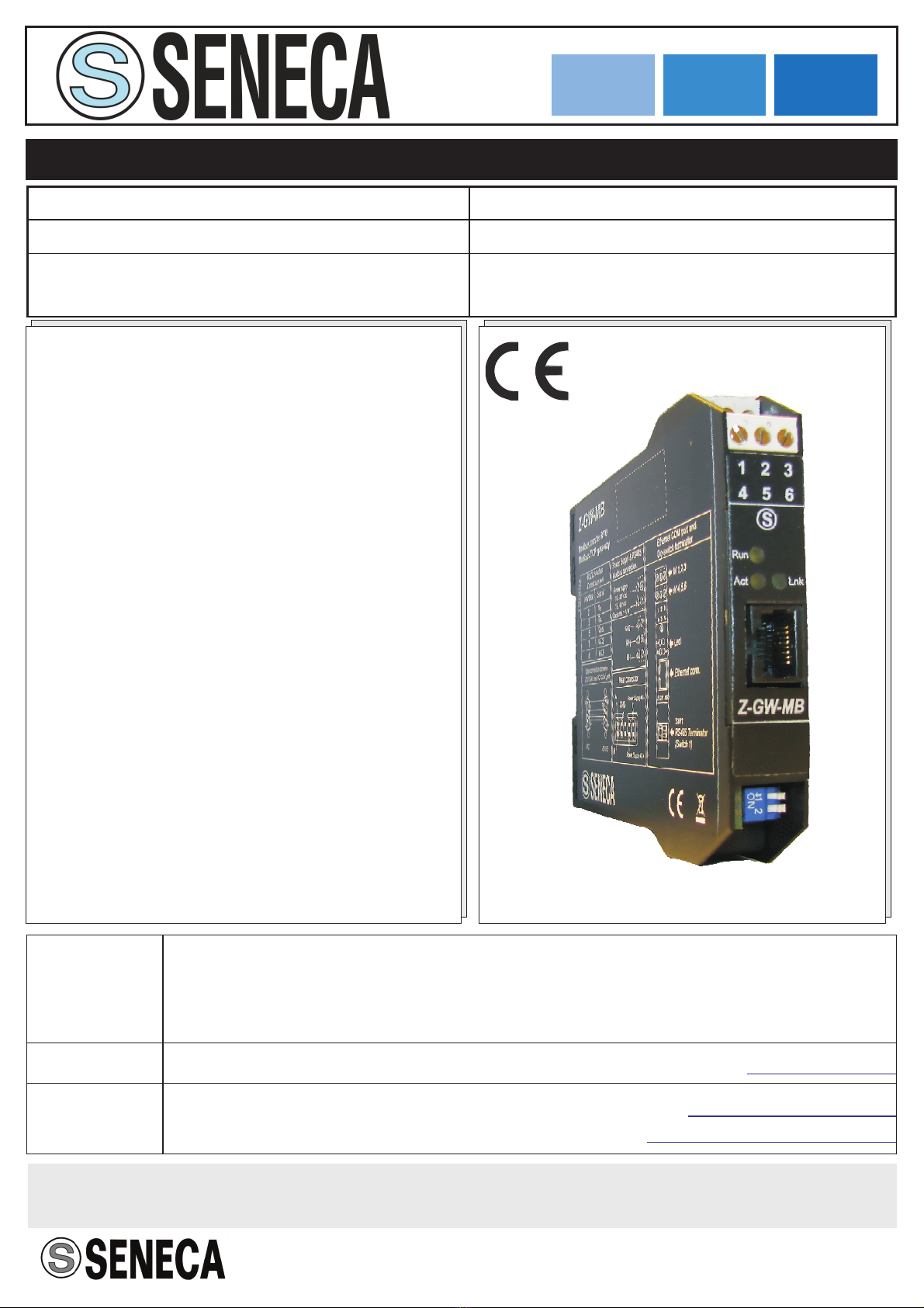
Seneca Z-GW-MB User manual
Other Seneca Gateway manuals

Seneca
Seneca Z-KEY User manual

Seneca
Seneca X-HDU Instruction Manual

Seneca
Seneca R-GWR User manual

Seneca
Seneca Z-KEY User manual

Seneca
Seneca Z-GW-MB User manual

Seneca
Seneca R-PASS User manual

Seneca
Seneca Z-KEY User manual

Seneca
Seneca Z-KEY User manual

Seneca
Seneca R-PASS User manual

Seneca
Seneca Z-KEY-P User manual

Seneca
Seneca Z-KEY-2ETH-P User manual

Seneca
Seneca Z-PASS2-IO User manual

Seneca
Seneca R-KEY-LT User manual

Seneca
Seneca Z-KEY-MBUS User manual

Seneca
Seneca Z-PASS2 User manual

Seneca
Seneca R-GWR User manual

Seneca
Seneca R-KEY-LT User manual

Seneca
Seneca Z-LINK2-LO User manual

Seneca
Seneca R-KEY-LT User manual

Seneca
Seneca Z-KEY-MBUS User manual


Popular Gateway manuals by other brands

LST
LST M500RFE-AS Specification sheet

Kinnex
Kinnex Media Gateway quick start guide

2N Telekomunikace
2N Telekomunikace 2N StarGate user manual

Mitsubishi Heavy Industries
Mitsubishi Heavy Industries Superlink SC-WBGW256 Original instructions

ZyXEL Communications
ZyXEL Communications ZYWALL2 ET 2WE user guide

Telsey
Telsey CPVA 500 - SIP Technical manual