SENSIT Technologies 906-00000-08 User manual

10-30-09 Revised 3-27-14 V5
SENSIT® HXG-2d
Combustible Gas Detector
INSTRUCTIONMANUAL
Read and understand Instructions before use.
#750-00022 Instruction Manual
Suitablefor combustiblegases
suchas Methane,Butane, Propane
andNatural Gas
MADE IN USA
Intrinsically Safe for Use in
Class I, Groups C and D, T3
Hazardous Locations
WARRANTY
YourSENSIT®HXG-2dinstrument iswarrantedto befree from
defectsin materialsand workmanshipfor aperiod oftwo years
after purchase (excluding sensor, calibration and batteries). If
withinthewarranty periodyourinstrumentshould becomeinop-
erativefromsuch defects,theunitwill berepairedorreplaced at
ouroption.This warrantycoversnormaluse anddoesnot cover
damagewhich occursin shipment orfailure whichresults from
alteration, tampering, accident, misuse, abuse, neglect, or im-
propermaintenance.Apurchasereceiptorother proofofdateof
originalpurchase willberequired beforewarranty performance
willberendered. Instrumentsoutof warrantywillbe repairedfor
aservice charge.Return the unitpostpaid andinsured to:
SENSITTECHNOLOGIES
851TransportDrive
Valparaiso, IN46383
Phone:(219)465-2700
Fax:(219)465-2701
This warranty gives you specific legal rights and you may also
haveother rights whichvary fromstate to state.
AEx ia IIB T3
IP20
For use in clean dry areas only.
710183
UL 913
www. .com information@itm.com1.800.561.8187

Page # 3 Accessories and Parts
4 General Description
5 Specifications
5-7 Product Features
7 Sensor Type
7 Sensor Filter Replacement / Cleaning
8 Battery Installation
9-11 Operation and Use
12 Calibration Check
12-13 Calibration
14 Sensor Replacement
15 Adjustable Features
16 Warranty and Repair Policy (Back Cover)
ACCESSORIESANDPARTS
Standard Accessories (included)
Soft Carrying Pouch 360-00006
T10 Torx Wrench 360-00105
Duracell “C”Alkaline Battery (ea) 310-00004*
Sensor Retainer Filter 360-00203
Wrist Strap 360-00040
Instruction Manual 750-00022
Optional Accessories and Parts
Extension Adapter 870-00012
Calibration Kit 2.5% Methane 881-00017
Calibration Kit .5% Methane 881-00075
LEL Sensor 375-2611-01
Sensor Cap 365-00045 3
CONTENTS
CAUTION: This safety symbol is used to indicate a potentially hazardous situation
which, if not avoided, may result in minor or moderate injury.
NOTICE
WARNING: This safety symbol is used to indicate a potentially hazardous situa-
tion which, if not avoided, may result in serious injury.
WARNING: Do not replace batteries when an explosive atmosphere
is present.
WARNING: Use onlyDURACELL®PROCELL,Type PC1400Alkaline
Batteries
WARNING: Do not mix batteries of different age or type.
WARNING: For use in clean dry areas only.
WARNING: Not for use in atmospheres of oxygen greater than 21%.
WARNING: Substitution of components may impair intrinsic safety.
WARNING: ONLYzero instrument in a gas free environment.
WARNING: To maintain intrinsic safety, service must be performed by
factory authorized technicians with approved replacement parts only.
WARNING: All Accessories are to be used in an area known to be
non-flammable.
WARNING: Use onlysensor fromSENSITTechnologies. PN375-2611-01
NOTE: Performance/Accuracy aspects of this product have not been
assessed and are not covered as a part of the SGS approval.
www. .com information@itm.com1.800.561.8187

4(Continued on page 5)
GENERALDESCRIPTION SPECIFICATIONS
5
BACKLITDISPLAY
SPEAKER
(ON BACK) WARNING LED
16”FLEXIBLE
GOOSENECK
SOLIDSTATE
SENSOR
PUSH BUTTONS
BATTERY
COMPARTMENT
BATTERYSLEEVE
RETAINING SCREW
SENSOR
FILTER
PRODUCTFEATURES
SENSORSPECIFICATIONS
TYPE RESOLUTION RANGE ACCURACY
PPM 10ppm 0-990ppm ±10%
LEL 0.1% 0-100%LEL ±10%
PRODUCTSPECIFICATIONS
Size: 10” x 3” x 1.6” (254 x 76 x 41 mm)
Weight: 1.2 lbs. (544g)
Operational Temp: -20 to 40°C (-4 to 104° F)
BatteryLife: Alkaline: 50 hours continuous
The Sensit® HXG-2d is designed to detect combustible gases.
This instrument incorporates an advanced low power semicon-
ductor sensor to measure a wide variety of combustible gases
in both the PPM and %LEL range. The PPM readings auto-range
to %LEL when the concentration exceeds 990PPM (2%LEL meth-
ane). Optionally all readings can be set to a resolution of
0.1%LEL only (PPM off).An “on demand” backlight allows use in
dark environments. A user activated “TICK” control assists in
locating small gas leaks. Audible and visual alarms warn the
operator of hazards. The alarms can be set in either the PPM or
LEL modes. The default alarm is 10%LEL methane.
The instrument is adjusted at the factory for either methane or
propane as the primary gas, and is calibrated accordingly. The
primary gas can be selected when ordering.
The Sensit® HXG-2d meets US UL913 requirements when used
with approved batteries.
The Sensit® HXG-2d is operated using approved alkaline bat-
teries only.
WARNING: Never mix batteries of different age or type.
www. .com information@itm.com1.800.561.8187

(Continued on page 7)
6
Combustible Gas Sensor
AllSensit® HXG-2d instruments incorporatea highlysensitive
semiconductor type sensor. The function and accuracy of the
sensoraremonitored andcontrolledbyspecialized circuitryand
a microprocessor. This sensor is capable of measuring
concentrations of 10ppm of methane up to 100% LEL. Factory
calibration uses methane gas. This sensor will detect many
combustiblegases.
PRODUCT FEATURES continued from page 5
7
PRODUCT FEATURES continued from page 6
SENSORFILTER REPLACEMENT/CLEANING
Removesensor cap bypressing retainingtablocated onsideof
sensor and pulling the cap away from base. Filter will be loose
inside.Clean filterwith mildsoap andwater and thoroughlydry
filtercap.ReplaceCap/Filteronbaseuntil retaining tabengages.
Sensit® HXG-2d instruments are constructed of durable high
impactABS to withstand the rigors of field use.
Incorporated in the hand grip area is the battery compartment.
All Sensit® HXG-2d instruments require 3. Duracell PC1400
batteriesprovide approximately50 hoursof continuous use.
A push button located in the center of the instrument activates
an audible tick sound that will help in locating the source of a
gasleak. Thistick is generatedby usingspecialized circuitryin
combinationwiththeLELsensorlocatedat theendofthegoose-
neck assembly. The tick can be easily heard with the speaker
located in the back of the instrument.
A flexible gooseneck is used to assist in locating the source of
gas leaks and remote sampling.
The display continuously updates the operator of changes in
gasconcentrationsand alertsoflowbatterypower.AgreenLED
on the left side indicates the instrument is ready for use.Ared
LEDindicates thepreset alarmpoints havebeen exceeded.
SENSORTYPE
There are 3 operational button pads on the front of all
Sensit®HXG-2d instruments.
(A)POWER/MUTEBUTTON:
Operate the POWER and MUTE feature and exit menu items.
(B)TICK/CALBUTTON:
Useto operateTICK orbegin calibration.
(C)LIGHT/ZEROBUTTON:
Use to turn on the backlight or manually zero the sensor.
www. .com information@itm.com1.800.561.8187

8
CAUTION: Always start any Sensit® HXG-2d in a gas free
environment to ensure a proper zero.
1. Push and hold the power button (A) until the display and backlight
illuminates.
2. If the display fails to illuminate or the BAT icon is shown on the
display, replace the batteries.
3. During successful start-up the instrument will display:
a. Display all segments
b. Turn on and off the backlight
c. Display “S2d” as the model number
d. Display software version
e. Display “50.0%” or “10.0%” indicating the LEL Calibration point
for the instrument
f. Display “dIS” indicating display resolution of PPM / %LEL
or both.
g. Display “AL” followed by the alarm set point.
h. Activate the alarm sound and red LED for 3 beeps
i. Continue to flash all segments until proper warm-up is
attained (no more than five minutes)
j. Flash “Zro” indicating fresh air zeroing
k. Working display is shown
NOTE:Afailure to properly zero due to the presence of gas is indicated
by “bAd” + cal icon illuminated on the display. Pressing the ZERO (C)
button for 6 seconds and releasing will restart the zeroing process.
NOTE: If a sensor is completely inoperable or improperly zeroed at
start up, the display will show “bAd”.
BATTERYINSTALLATION/REPLACEMENT
9(Continued on page 10)
OPERATIONANDUSE
WARNING: Always change batteries in an environment
free of combustible gases.
WARNING: Do not mix batteries of different type or age.
Battery replacement is necessary when the BAT icon is illumi-
natedandthegreenLEDisflashing.Thiswarningindicatesthere
is approximately 15 minutes or less operational time before the
instrumentturnsoffautomaticallyduetoinsufficientbatterypower.
Removethe batterysleevecover byremovingthe batterysleeve
screwwithaT-10screwdriver.Depressthelockingtabonthefront
of the handle with a coin or flat object and pull the battery sleeve
handleaway fromthetop ordisplay areaofthe instrument.
Place3 approvedbatteries intothe batteryholder. Observethe
polarity markings on the inside of the battery holder for proper
batteryinstallation.Improperinstallationwillcausetheinstrument
not to operate. Replace the battery sleeve and allow the locking
tabtosnapintoposition.Replacethebatterysleeveretainingscrew.
Check to be sure the handle is secure to the instrument body by
firmlypullingthehandleaway.Thehandlewillremaininplaceif a
properconnectionismade.
www. .com information@itm.com1.800.561.8187

(Continued on page 11)
10
OPERATION AND USE continued from page 8
NOTE:Theseinstrumentshavecrosssensitivitiestoa varietyof
gases.
9. To assist in locating the source of small combustible gas
leaksorsurveying areasoutdoorsor indoors,pressandrelease
theTICK/CAL button(B). Thiswill startanaudible tickpreset at
2-3 ticks per second.
Move thesensor towardthe areasuspected ofleakage.As the
sensor moves closer to a leak source the tick will increase.
Whenthe tickbecomes asteady tonepress theTICK/CAL but-
ton (B) again while keeping the sensor head in the same posi-
tion.This willslow downthe tickand allowthe operatortofind a
higherconcentration usingthe sameprocedure.
If there is no tick, press the TICK/CAL button (B) again to reset
to the steady ticking sound. For best results always use the
leak detector prior to using any liquid leak detection fluids as
these sensors will detect their presence.
10. Following Country, Province, State, Municipal and/or Com-
panyproceduresmovetothe areas wheregasreadingsaresus-
pectedor mustbe tested.Duringsampling therespective read-
ings may change.Audible and visual alarms will activate when
the preset limits are reached.
11. Whenbeing usedindarkareaspressandreleasetheLIGHT/
ZERObutton(C) toturnon thebacklight Pressagaintoturn off.
12. To turn instrument off, push and hold the POWER/MUTE
button (A) for 5-6 seconds until “OFF” appears on the display.
11
OPERATION AND USE continued from page 10
4. Allinstrumentsreadwitharesolutionof10ppmupto 990ppm.
ThescaleautomaticallyswitchtoLELwhen990ppmisexceeded
with a resolution of 0.1% LEL. Optionally all readings may be
displayed in LEL only. Readings beyond 100% LEL are indi-
catedby“OL” (overload).
5. It may be necessary to manually zero the instrument based
oncompany practicesand environmentalconditions.
CAUTION: Zeroing should be done in a gas free envi-
ronment only.
6. When testing high areas or overhead lines the use of the
optionalextensionadapter willallowa broomhandleorpainters
stick to extend the instrument to the area where sensing must
be accomplished. This slides onto the battery sleeve and is
held in place by the locking nut assembly.
7. When a gas is sensed the display will update. If an alarm
conditionexists, basedona presetalarmpoint, theredLED will
flash and the alarm will sound.
8.Duringan alarm condition (factory defaultat 10%LEL meth-
ane) the display will flash and an audible alarm will sound indi-
catinga potentiallyunsafe environment.Todisable theaudible
alarm press and release the MUTE button (A). To enable the
alarmpress and release it again.
www. .com information@itm.com1.800.561.8187

12 13
CALIBRATION continued from page 12
Step 3:Attach the adapter to the sensor cap assembly.
Step4:Press theTICK/CALbutton (B)andthe caliconwill flash
and numbers will change on the display. Upon completion, the
workingdisplay willappear withthe gas reading.
A reading of “bAd” indicates unsuccessful calibration. Repeat
processif “bAd” appears.Press thePOWER/MUTE button (A)
toclear the“bAd”display readingand goto theworkingdisplay.
Continuedunsuccessfulcalibrations mayindicatefaulty sensor.
Any instrument that will not calibrate or continues to indicate
“bAd” on the display, should be taken out of service. Please
contact SensitTechnologies for further assistance.
CALIBRATIONCHECK
To verify the accuracy of any Sensit® HXG-2d it must be ex-
posed to a known concentration of test gas. Any sensor that
does not meet the specifications listed in this manual may re-
quirecalibration orreplacement.
AnytimeitissuspectedtheSensit®HXG-2disnotworkingproperly,
hasread“OL”or hasbeenexposedto silicone,checkcalibration.
Calibration is the process of setting the readings of the instru-
ment to equal the value of the certified calibration gas. The in-
strumentshould operatefor 5minutes beforecalibrating.
NOTE: Use of calibration kits other than those offered or ap-
provedbySENSITTECHNOLOGIESmaycauseinaccurateread-
ings.Repairs may berequired if theinstrument failstocalibrate.
UseonlysensorssuppliedbySENSITTECHNOLOGIESor their
authorizedrepresentative.
NOTE: During the calibration process the numbers on the dis-
play are not the actual gas concentration.
Step 1: Prepare 50%LELor 10% LEL Methane/Air, depending
on what calibration point the unit calls for, and proper regulator
andadapter.
Step2:PresstheTICK/CALbutton(B)for6 secondsuntil “GAS”
is displayed.
CALIBRATION
(Continued on page 13)
www. .com information@itm.com1.800.561.8187

14 15
ADJUSTABLEFEATURES
The Above settings are field adjustable:
Setting Display Mode For %LEL & Alarm Setpoint For %LEL
1. While the unit is on and in the working display, push the A and C buttons until the
display shows OPt.
2. Press the B button once until the display shows diS%. This indicates the working
display will show measurements in %LEL.
3. Press the B button once more until the display shows AL%. This indicates the
alarm setpoint can be set in units of %LEL.
4. Press the B button once more until the display shows XX.X%. This is the alarm
setpoint (XX.X can be values of 0-9).
5. Press the C button to increment the alarm setpoint or press the B button to
decrement the alarm setpoint (Minimum 2.0%LEL, Maximum 60.0%LEL)
6. Press the A button once to exit to the OPt menu.
7. Press the A button once more to exit to the working display which will show
measurements in %LEL.
Setting Display Mode For PPM & %LEL & Alarm Setpoint For PPM
1. While the unit is on and in the working display, push the A and C buttons until the
display shows OPt.
2. Press the B button once until the display shows diS%. This indicates the working
display will show %LEL measurements.
3. Press the C button once until the display show diS% ppm. This indicates the
working display will initially show ppm measurements then transition to %LEL
measurements once the unit measures greater than 990ppm.
4. Press the B button once more until the display shows AL ppm. This indicates the
alarm setpoint can be set in units of PPM.
5. Press the B button once more until the display shows XXXppm. This is the alarm
setpoint; it must be set to a PPM value greater than or equal to 100ppm to
activate the PPM alarm.
6. Press the C button to increment the alarm setpoint or press the B button to
decrement the alarm setpoint (PPM Alarm Off: 99ppm, Minimum 100ppm,
Maximum 990ppm)
7. Press the A button once to exit to the OPt menu.
8. Press the A button once more to exit to the working display which will show
measurements in PPM.
SENSORREPLACEMENT
Step1: Turnoffinstrument.
Step2: Removesensor capand sensorretainerfilter.
Step3: Removesensor.Observe thelocationof thetab relative
to the white dot beneath, on the circuit board.
Step4: Replacesensor. Besure toalign thesensor tab directly
overthe whitedot.
Step5: Placesensor retainerfilter insidesensor capand install
sensorcap.
Step6:Turninstrumentonandwaitforzeroprocesstocomplete.
“bAd”indicatesimproperlyinstalledsensororadditionalwarm-up
time is required. Allow the instrument to operate for 10 minutes,
then press and hold the C button to reestablish zero. If “bAd”
remainsonthedisplay,removetheinstrumentfromservice.
Step 7: If zeroing of the replacement sensor was successful
and at least a 5 minute warm-up has been observed, proceed
with the calibration instructions.
WARNING: Perform service only in areas known to be non-
flammable.
WARNING:Substitutionofcomponentsmayimpairintrinsicsafety.
WARNING: Use only sensor from SENSIT Technologies.
Part Number 375-2611-01
Alarm PPM 100-990 OFF
Alarm-LEL 2-60% 10%
Show PPM 10PPM Resolution ON
MENU ITEMS RANGE DEFAULT
www. .com information@itm.com1.800.561.8187
This manual suits for next models
3
Table of contents
Other SENSIT Technologies Gas Detector manuals

SENSIT Technologies
SENSIT Technologies IRED User manual

SENSIT Technologies
SENSIT Technologies VMD Operating instructions
SENSIT Technologies
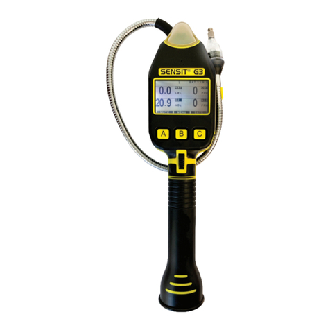
SENSIT Technologies GOLD G3 User manual
SENSIT Technologies
SENSIT Technologies Gas Trac LZ-30 Programming manual
SENSIT Technologies
SENSIT Technologies GAS-TRAC LZ-30 User manual
SENSIT Technologies
SENSIT Technologies IRED User manual

SENSIT Technologies
SENSIT Technologies GAS-TRAC LZ-30 User manual
