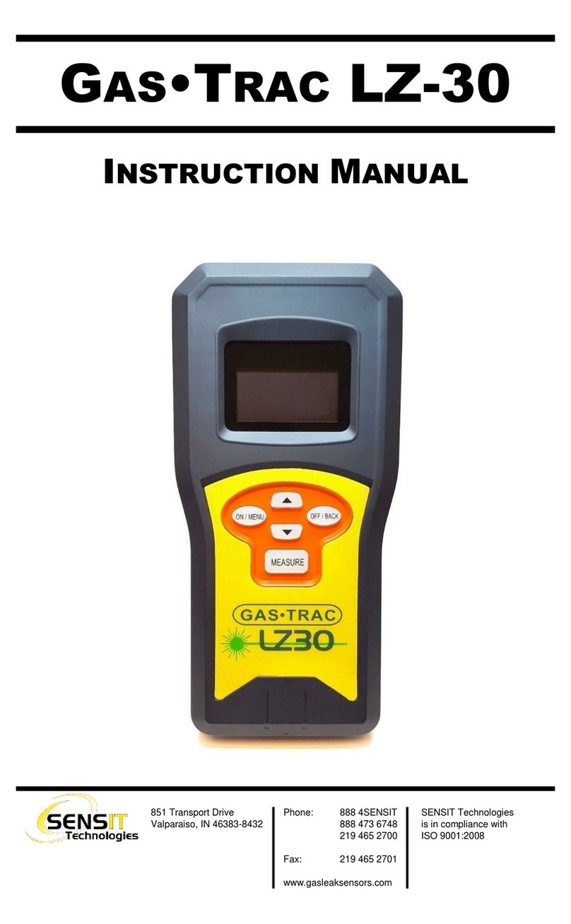
SENSIT Technologies GAS-TRAC LZ-30 User manual

851 Transport Drive • Valparaiso, IN 46383 (USA)
Phone: 219.465.2700 • www.gasleaksensors.com
INSTRUCTIONAL MANUAL
Read and understand instructions before use.

CONTENTS
FOR YOUR SAFETY ............................................................ 3
PARTS AND ACCESSORIES ................................................. 5
STANDARD ACCESSORIES (INCLUDED)....................................................... 5
ACCESSORIES AND REPLACEMENT PARTS .................................................. 5
GENERAL DESCRIPTION..................................................... 6
SPECIFICATIONS ............................................................... 7
PRODUCT FEATURES.......................................................... 9
PRODUCT FEATURES.......................................................... 10
BEAM DIMENSIONS ................................................................................. 10
SMART-LINK LIVE (PAID OPTION) ...................................... 11
SENSOR TECHNOLOGY...................................................... 12
GAS DETECTION ...................................................................................... 12
DISTANCE DETECTION.............................................................................. 12
EXPLANATION OF PPM•M ................................................ 13
OPERATION AND USE ....................................................... 14
OPERATION AND USE TIPS ................................................ 15
INVESTIGATING THROUGH WINDOWS ..................................................... 15
SHAPE OF THE DETECTION BEAM AND LINE OF SIGHT .............................. 16
WIND CONDITIONS AND PLUME SIZE....................................................... 17
LOCATING TARGETING LASER ................................................................... 17
CALIBRATION CHECK (BUMP TEST)..................................... 19
CALIBRATION ................................................................... 19
USER MENU...................................................................... 20
CALIBRATION........................................................................................... 21
BLUETOOTH ID.......................................................................................... 21
SET ALARM .............................................................................................. 21
SET RED LASER ......................................................................................... 21
SET GREEN LASER..................................................................................... 21
SET UNIT.................................................................................................. 22
DISTANCE UNITS ...................................................................................... 22
3 TIER ALARM........................................................................................... 22
LANGUAGE ............................................................................................. 22
RESET....................................................................................................... 23
SMART-LINK LIVE SETUP ..................................................... 24
MAINTENANCE AND CARE ................................................ 25
NOTES.............................................................................. 26
REQUIREMENTS UNDER WEEE REGULATIONS ..................... 27
WARRANTY ...................................................................... 28

3
FOR YOUR SAFETY
⚠ NOTICE: This safety symbol is used to indicate a potentially hazardous situation which,
if not avoided, may result in minor or moderate injury.
__________________________________________________________________________________________
⚠ WARNING: Read and understand this manual fully before use.
⚠ WARNING: Battery is not user replaceable.
⚠ WARNING: To maintain Class 1, Division 2 hazardous location approval, any disassembly
or repair of the instrument must be done by a factory certified technician. No
substitution of components is permitted.
⚠ WARNING: The appliance is not to be used by persons (including children) with
reducesphysical, sensory, or mental capabilities, or lack of experience and
knowledge, unless they have been given supervision or instruction.
⚠ WARNING: The appliance is not to be used by persons (including children) with reduces
physical, sensory, or mental capabilities, or lack of experience and knowledge,
unless they have been given supervision or instruction.
⚠ WARNING: Only charge instrument in an area known to be non-hazardous.
⚠ WARNING: Charger is not approved to be used in a hazardous area. Charger must be
used and stored in a clean, dry, non-hazardous area.
⚠ WARNING: Use only GASTRAC® LZ-30 CHARGER BASE KIT (871-00064) with the
GASTRAC® LZ-30 Instrument (834-00000-01).
⚠ WARNING: Follow the manual instructions and testing methods.
⚠ CAUTION: Continuously low calibration check results may indicate sensor end of life or
failure. Consult SENSIT Technologies with any questions.
⚠ CAUTION: Use of controls or adjustments or performance of procedures other than those
specified herein may result in hazardous radiation exposure.
⚠ DANGER: Do not point the instrument towards the sun, or other extreme sources of light/
heat. Damage may occur.
⚠ DANGER: Avoid direct eye exposure to the laser and do not point in the direction of
others. Visible and Invisible Lasers are deployed by this instrument.

4
FOR YOUR SAFETY
⚠ CAUTION: Laser radiation. Avoid direct eye exposure. Class 3R laser product.
LASER WARNING LABEL LOCATION
The laser warning label is located on the back of the instrument. Refer to the label pictured in the lower
right for details.
LASER
APERTURES
710183
Warning label indicating the GasTrac LZ30 contains a
class 3R laser and to avoid direct eye exposure with
the laser.
This symbol indicates the location of the laser aperture.
Product Certification Mark from the General Society of
Surveillance.

45
PARTS AND ACCESSORIES
STANDARD ACCESSORIES (INCLUDED)
330-00049 D-ring
331-00155 D-ring screw
360-00040 Wrist Strap
750-00080 Instruction Manual (English)
750-00080-01 French
750-00080-02 German
750-00080-03 Italian
750-00080-04 Polish
750-00080-05 Spanish
870-00098 Shock Protective Boot
871-00074 Charging Kit (charging base + power supply, for units with shock protective
boot)
872-00035 Hard Carrying Case (for units with shock protective boot)
882-00150-SN Calibration/Bump Test Cell
ACCESSORIES AND REPLACEMENT PARTS
871-00063 Multi-Blade Power Supply for Charging Base
871-00072 Charging Base (for units with shock protective boot)
871-00064 Charging Kit (charging base + power supply, for units without shock protective
boot)

6
GENERAL DESCRIPTION
The GAS•TRAC LZ-30 is a methane selective, laser-based gas detector. The device is based on world-
leading photonic technology and is designed using the effect that methane gas absorbs a certain laser
wavelength, and the absorbing strength is related to the concentration of the methane.
The device is a handheld gas detector, for the remote detection of methane and gases containing methane
(natural gas and naturally occurring sources of methane). By pointing its beam of laser light to the testing
target, a concentration result can be read immediately within a distance of 0.5 to 30 meters. By sending
the beam of the laser to the target destination, the device measures the laser signal returned from the target
destination. The methane concentration along the reflected beam path will be calculated and displayed.
In addition, the GAS•TRAC LZ-30 measures the total distance to the target and displays the result in
real-time along with the gas reading.
The laser modules specifications are Class IIIR, with a power output of less than 5mW for the distance
detection laser and spotter laser, and a power output of less than 50mW for the IR (gas detection) laser.

67
SPECIFICATIONS
DETECTION TECHNOLOGY: Tunable Diode Laser Absorption Spectroscopy (TDLAS)
METHANE DETECTION RANGE: 0-50,000ppm•m in 1ppm•m increments
SENSITIVITY: 5ppm•m ≤15m (50ft)/10ppm•m ≤30m (100ft) @ ≥
300ppm•m
RESPONSE TIME: ≤0.1 seconds
DETECTION DISTANCE: 0.5m to 30m (1.5’ to 100’) Distance may vary slightly
depending on reflection
DISTANCE INDICATOR: 0.2m to 30m (6” to 100’) Range may vary slightly
depending on reflection
BEAM DIMENSION: Conical, 20cm diameter at 30m (8” at 100’)
ALARMS: Adjustable threshold alarm with baseline: Visual, audible,
and tactile (vibrating motor)Default: 100ppm•m
WARNINGS: Low Reflection, High Reflection, Low Battery, High Methane
CALIBRATION/SELF CHECK: Built-in self-test/bump test and calibration with test cell
incorporated in carrying case
LASER CLASSIFICATIONS: IR laser (methane detection) Class IIIR
Target laser (green) Class IIIR
Distance laser (red) Class IIIR
COMMUNICATION: Bluetooth, supported by Android
DISPLAY: OLED

8
SPECIFICATIONS
OPERATIONAL TEMP: -20C to 50C (-4F to 122F)
STORAGE TEMP: -40C to 60C (-40F to 140F)
HUMIDITY: ≤98% non-condensing
ENVIRONMENTAL CONDITIONS: (Indoor/Outdoor use)
Altitude (<=2000 meters)
Pollution Degree (pollution degree 4)
INGRESS PROTECTION: IP64
INTRINSIC SAFETY: IEC/UL/CSA 61010-1
WEIGHT: 300g (0.7lbs)
SIZE: H-6.5 x W-3.1 x D-1.4 in (164.5 x 78.8 x 35.1 mm)
POWER SOURCE: Internal Lithium Ion, 2400mAh
BATTERY LIFE: I6.5 Hours Continuous
RECHARGE TIME: 3 to 4 Hours
VOLT RATING: 4.2V
CURRENT RATING: 1A

89
PRODUCT FEATURES
GAS•TRAC LZ-30 instruments are constructed of durable flame-retardant polycarbonate plastic to
withstand the rigors of field use.
The housing contains a rechargeable Lithium Ion battery, which is charged by inserting the instrument into
the charging base.
Open-path TDLAS technology ensures that gas detection is instantaneous, accurate, and methane specific
– up to a distance of 30m (100ft).
The operator will be given real-time gas readings on an easy to read OLED display, displayed in ppm•m
by default, along with a distance measurement for the current target.
The alarm comes in the form of an audible tone, a visual indication via a red backlight on the measure
button, as well as a vibrating motor. There is 1 adjustable alarm threshold, and 2 varying types of alarms
at 50% and 100% of this threshold (low and high). When the high alarm is reached, the frequency of the
audible tone will increase and the vibrating motor will turn on.
DETECTION LASER
(IR, NOT VISIBLE)
DISTANCE LASER (RED)
TARGETING LASER (GREEN)
BACKLIT OLED DISPLAY
OPERATION BUTTONS
DURABLE, FLAME-RETARDANT
POLYCARBONATE HOUSING
CHARGING PINS FOR INTERNAL
RECHARGEABLE BATTERY

10
PRODUCT FEATURES
BEAM DIMENSIONS
The GAS•TRAC LZ-30 produces a conical beam of laser light, that starts from the front of the instrument
and gradually spreads as the distance increases. At the maximum detection distance, 30m, this beam is
8” in diameter. This is depicted in the image below (not to scale).

10 11
SMART-LINK LIVE (PAID OPTION)
TRY IT FREE FOR 30 DAYS
SENSIT Technologies offers an app (currently Android only) called SMART-LINK LIVE that can be
used in conjunction with the GAS•TRAC LZ-30. This app allows the user to continuously capture live
readings from the LZ-30, along with date/time stamps and GPS coordinates. This data can then be viewed
on a map or exported and transferred to a PC.
NOTE: To be compatible with Smart-Link Live, the LZ-30 must have firmware version 4.1 or newer
(displayed on startup).
Access to licensing for the SMART-LINK LIVE app can be purchased along with the GAS•TRAC
LZ-30 when an order is made for a new instrument. If you already own a GAS•TRAC LZ-30 and
want access to the app, contact SENSIT Technologies to obtain licensing for your instrument. Then,
search “Smart-Link Live” on the Google Play store, select the app, and hit “Install”.
The app is free to install but will not work with your instrument unless you obtain licensing from SENSIT
Technologies, after the 30 day free trial.

12
SENSOR TECHNOLOGY
GAS DETECTION
The GAS•TRAC LZ-30 uses open path TDLAS (tunable diode laser absorption spectroscopy)
technology. The laser generates a specific wavelength of light that is sent through the gas monitoring area,
partially absorbed by any methane source, and reflected back to the instrument by the reflection surface.
The higher the methane concentration, the larger the absorption will be, resulting in a higher reading.
Using this technology in an open path allows for the instrument to detect gas remotely, simply by pointing
at the target anywhere from 0.5 to 30 meters away from the operator.
DISTANCE DETECTION
There is a separate laser that is used specifically for distance detection. It sends a laser pulse to the target
in a narrow beam and measures the time taken from when it leaves the instrument to when it returns, from
the reflection surface. Using this time measurement, the distance is determined based on the speed of light.
Both the distance and gas detection rely on a surface that is reflective enough to return the signal to the
instrument. Most solid surfaces will work. Changes in reflectivity can cause variance in both the gas and
distance measurements.

12 13
EXPLANATION OF PPM•M
The GAS•TRAC LZ-30 displays its readings in parts per million meter (ppm•m). This is a representation
of the average gas concentration over 1 meter, or roughly 3.3 feet.
The detection laser of the GAS•TRAC LZ-30 measures the amount of light absorbed by a concentration of
gas. However, there is no way of knowing the size of the plume. Because of this, higher concentrations
over a small area or smaller concentrations over a large area can give the same reading on the screen.
While point and shoot technology of this nature is a great indication tool, and can be used to pinpoint the
source of a leak by comparing readings, it cannot be used to quantify a gas leak.
See the diagram to the right. On the
top, there is a gas plume 0.5 meter in
length with a concentration of 2,000
ppm methane. On the bottom, there is
a gas plume 1 meter in length with a
concentration of 1,000 ppm methane.
The GAS•TRAC LZ-30 will see the
same amount of absorption in both
scenarios, and therefore give the same
reading of 1,000 ppm•m.
In addition, in a real-world scenario
there will be some small amount of
background methane in ambient air.
This is generally about 2 ppm•m.
So for a reading at 30m (100ft), the
reading on the screen would be about
60 ppm•m higher.

14
OPERATION AND USE
⚠ WARNING: When the GAS•TRAC LZ-30 is powered on, the laser module(s) will be
energized.
1. Press and hold the ON/MENU button until thescreen illu-
minates. The software version willbe displayed during a
brief warmup period(~15 seconds).
2. If the displays fails to illuminate or a lowbattery indica-
tion is show, place theinstrument in the charging base to
chargethe battery.
3. After warmup, the instrument will show thefollowing on
what is called the work display:
a. (Upper left)Distance measurement
b. (Upper right)Fuel gauge
c. (Center)Current methane reading
d. (Lower left)Peak methane reading
e. (Lower right)Measurement unit/scale
4. A bump test can be performed before each use. See the
“CalibrationCheck (Bump Test)” section on page 22 of
this manual for moreinformation.
5. To begin an investigation, press and release the MEASURE button.During measurement, the tar-
geting laser (green) will ash on and offcontinuously, as well as an audible beeping to alert the
operator thata measurement is active. A distance measurement and the currentand peak methane
readings will be displayed on the screen.
6. Using the visible targeting laser, survey the area according to federal,state, municipal, and/or
company procedures. Observe the readingson the display and any alarm conditions that should
occur. In general,it is good practice to conduct investigations using an ‘S’ or ‘Z’ patternto maxi-
mize the area that is scanned.
7. If at any time the instrument gives a low or high reection warning,indicated by REF/L or REF/H
on the display as well as an audible tone,try a different angle, position, or distance in order to
increase ordecrease the amount of reected light. These messages indicate thatthe instrument is
not getting an appropriate amount of reected light.Be aware that not all surfaces may be suitable
for reection.
NOTE: The relative signal strength of the reectedsignal is indicated on the
display next to the fuelgauge.
8. If at any time the instrument displays HIGH METHANE, this is anoverload message indicating that
you are detecting gas greater thanthe upper detection limit of the instrument (50,000 ppm•m).
9. To stop a measurement, press and release the MEASURE buttonagain.
10. To access the user menu, press and release the ON/MENU button.The user menu cannot be
accessed if a measurement is currentlyactive. See the User Menu section of this manual for more
details.
11. To power off the instrument, press and hold the OFF/BACK button. Abrief animation will show.
Keep the button held down until the screengoes blank.

14 15
OPERATION AND USE TIPS
Factors such as line of sight, wind, and sunlight conditions are not something that most operators have
had to take into account in the past. This section gives a few tips and tricks for getting the most out of the
GAS•TRAC LZ-30.
NOTE: Federal, state, municipal, and/or company procedures supersede what is outlined in this section.
INVESTIGATING THROUGH WINDOWS
The laser technology used in the GAS•TRAC LZ-30 allows the instrument to detect through standard
window glass. This is a big advantage as it allows the user to investigate the inside of a building (for
example) when he/she otherwise might not have been able to gain access.
In order to get the best results in this type of a scenario, follow these steps:
1. Maintain an angle of attack that is less than 90˚to
your target, and ideally between 45˚ and 75˚.This is
depicted in the image to the right.This greatly reduces
the chance of what isknown as “specular reections”,
which is whena portion of the laser reects off of the
surfaceof the window. It is also especially helpful for-
double-pane windows where the laser mightreect/
bounce multiple times between thepanes.
2. Use the distance measurement on-screen tohelp de-
termine if the lasers are actuallypassing through the
window. For example, ifthe distance measurement on
a wall next tothe window reads 15m and on the win-
dowreads 20m, you can be reasonably sure youare
detecting through the window.
If instead they are the same distance, thelaser is just
reecting off of the window. Ananti-reective coating
on the glass maycause this.

16
OPERATION AND USE TIPS
SHAPE OF THE DETECTION BEAM AND LINE OF SIGHT
Due to the GAS•TRAC LZ-30 using a point of light for targeting, it can be easy to forget that the actual
detection path is in the shape of a cone, which starts from a point (the instrument) and gets wider on the
path to the target. At a distance of 30m (100ft.), this width is 20cm (8in.).The operator will get the most
consistent results if he/she keeps as much of this path in/over the target as possible.
Because of this, some situations can present a challenge,
such as if part of the beam is reflecting off of a different
surface than another. This is known as “beam skipping”.
The operator will get the most consistent results if he/
she keeps as much of this beam in/over the target as
possible.
In the picture to the right (beam not to scale), part of
the beam is partially blocked by the fence, potentially
causing reduced sensitivity, or in some cases, false
positives. The operator should simply move slightly to the
left, ensuring that the full width of the beam will make it
to the target.
If the operator were surveying the ground behind the
fence, this wouldn’t be too great of a mismatch, but if the
target was the face of the building in the background,
there would be a very large difference in return signal
between the portion of the beam that is hitting the
building and the portion that is hitting the fence.
SHAPE OF THE DETECTION BEAM AND LINE OF SIGHT
Another thing to consider is that the size of the beam can affect the
reading that the instrument gives, depending on the size of the plume.
Consider the picture to the right: the green colored beam is roughly the
same size as the plume of gas, which means that the instrument will be
reading only that plume. In the case of the red beam, only half of it is
traveling through the plume, meaning that the result on-screen is going
to be lower because part of what is being analyzed is gas-free air.
What this means is that the distance between the operator and the
plume can potentially affect the reading, because the beam expands
with distance. Realistically, though, it is unlikely to cause a noticeable
effect due to the gas plume naturally dispersing over a (relatively) large
area. Where this might be more noticeable is if the operator is far
away from a very small pinpoint leak. Most of the beam will not be
hitting the plume, and will lower the reading.
In a real-world scenario, a gas plume doesn’t have strictly defined
edges like this, and the operator obviously won’t be aware of where it
is to begin with. However, what this illustrates is that technology of this nature makes it near-impossible to
get true quantitative results. There are simply too many variables. Qualitative investigation and pinpointing
is where it shines.

16 17
OPERATION AND USE TIPS
WIND CONDITIONS AND PLUME SIZE
Since the path of the laser has to pass through the methane plume for detection, wind conditions can
greatly affect how the instrument operates. Because of this, especially when scanning a large area, it
makes sense to have a plan of attack.
Ensuring the laser is passing through the plume from downwind or upwind will generally result in much
higher readings, because the path-distance through the gas is much greater than from crosswind. However,
higher readings do not always mean there is also a higher chance for detection. Many times a crosswind
scenario would yield a much higher chance that the gas will be detected, because a much larger portion
of the user’s field of view, or scan-able area, will contain gas.
The picture below shows an example with a top-down view. If the user is scanning the entire area, there is
a greater chance for detection in the crosswind case because a larger portion of the field of view contains
gas. Anywhere the LZ-30 is moved across the frame, the plume will be detected. However, in the upwind
case, if the user points straight through the plume, the entire distance from the instrument to the source will
contain gas, and so the reading on-screen will be much higher. Anywhere else that the LZ-30 is pointed
will result in the plume being missed.
This is a very simplified example, but this behavior is an important aspect of remote investigation.
NOTE: This is not about the size of the response, but greatest chance of detection.
LOCATING TARGETING LASER
With bright sunlight, the targeting laser may be difficult for some to see. This is unfortunately a downside
of any technology of this nature. There are a few things that can help with this.
One thing that might help in this scenario is to begin tracking the laser from a location where you can
see it clearly. For example, point the instrument at the ground in front of your feet, and gradually sweep it
forward, away from you, to your target. Your eyes will have a much easier time following a moving target
than finding a missing one.

18
Additionally, the operator can use laser enhancement glasses. This can increase the contrast of the
targeting laser, making it easier to see against certain backgrounds. Below is a view with and without
these glasses.

18 19
CALIBRATION CHECK (BUMP TEST)
⚠ WARNING: The built-in calibration cell in the carrying case must be used for bump testing.
The calibration gas in the cell is certified for 3 years (labeled on the cell),
after which it is considered to be expired. Cells can be sent into SENSIT
Technologies to be refilled and recertified.
To verify the accuracy of any GAS•TRAC LZ-30, a bump test must be performed. This is done using
the calibration cell, which is built into the hard carrying case. A bump test can be performed before each
use since it is so quick to do and uses no consumables.
A sensor that does not meet the specification listed below may require calibration or repair. Any time it is
suspected that the GAS•TRAC LZ-30 is not working properly, perform a bump test.
Power on the instrument and allow the warmup process to complete before proceeding.
STEP 1: Place the instrument in the carry case. Ensure both the instrument and calibration cell are
fully seated. Ensure there are no obstructions in the path between the instrument and cell.
STEP 2: Press and release the MEASURE button to begin a measurement. Allow the unit to read for
a few seconds.
STEP 3: Press and release the MEASURE button again to stop the measurement. The reading on
the center of the screen should be 1,500 ppm•m (3.0%LEL / 0.15%V/V) or greater for a
successful test.
NOTE: If the result is less than 1,500 ppm•m (3.0%LEL / 0.15%V/V), attempt the bump test
again. If still unsuccessful, perform a calibration.
CALIBRATION
⚠ WARNING: The built-in calibration cell in the carrying case must be used for calibration.
Using any other calibration kits or gas may cause inaccurate readings.
Repairs may be required if the instrument fails to calibrate. Consult SENSIT
Technologies for details. The calibration gas in the cell is certified for 3 years
(labeled on the cell), after which it is considered to be expired. Cells can be
sent into SENSIT Technologies to be refilled and recertified.
Calibration is the process of setting the reading of the instrument equal to the value of the certified
calibration gas inside the calibration cell. Power on the instrument and allow the warmup process to
complete before proceeding.
STEP 1: Place the instrument in the carry case. Ensure both the instrument and calibration cell are
fully seated. Ensure there are no obstructions in the path between the instrument and cell. Do
not remove the instrument until “Pass” is displayed in step 5.
STEP 2: Press and release the MEASURE button to begin a measurement. Allow the unit to read for
a few seconds.
STEP 3: Press and release the MEASURE button again to stop the measurement. The current reading
of the calibration cell will remain on the screen.
STEP 4: Press and release the on/menu button to enter the user menu. CALIBRATION 2000
PPM•M should be shown on the display. If not, continue to press and release the button
until it is shown.

20
STEP 5: Press and release the measure button. If the calibration is successful, “Pass” will be displayed
on the screen.
NOTE: If instead “Fail” is displayed, the calibration was unsuccessful. Attempt calibration
again from step 2. After two consecutive failures an advanced calibration will be
automatically performed. This is shown as “Wavelength Advance Cal.” on the display and
can take up to 5 minutes to complete.
If the advanced calibration fails, a “Service Required” message will be displayed. Any
instrument that cannot be successfully calibrated should be taken out of service. Please
contact SENSIT Technologies for further assistance.
USER MENU
The user menu gives the user access to the calibration menu and various settings, including the alarm point
and turning the indication lasers on or off.
To access the user menu, press and release the ON/MENU button from the work display. The first menu
item, CALIBRATION, will be displayed.
NOTE: The menu is not accessible if the measurement function is activated.
NOTE: Some options in the user menu are password protected. They are noted as such above each
description. Contact SENSIT Technologies if you need to make adjustments to these
settings.
To scroll through this menu, continue to press and release the ON/MENU button. The arrow buttons will
adjust/change the current setting on the screen.
To exit the user menu, press and release the OFF/BACK button.
LASER APERTURES
EXIT
SAVE SETTING
ADJUST
ENTER MENU/
ADVANCE
Other manuals for GAS-TRAC LZ-30
4
Table of contents
Other SENSIT Technologies Gas Detector manuals

SENSIT Technologies
SENSIT Technologies IRED User manual

SENSIT Technologies
SENSIT Technologies GAS-TRAC LZ-30 User manual

SENSIT Technologies
SENSIT Technologies 906-00000-08 User manual

SENSIT Technologies
SENSIT Technologies Gas Trac LZ-30 Programming manual

SENSIT Technologies
SENSIT Technologies IRED User manual

SENSIT Technologies
SENSIT Technologies GOLD G3 User manual

SENSIT Technologies
SENSIT Technologies VMD Operating instructions