SGM P-6 User manual

USERMANUAL
P-6
Product Version 1.0 | Document Revision E | Released 2022-12-09

2Product Version 1.0 | Revision E | Released 2022-12-09
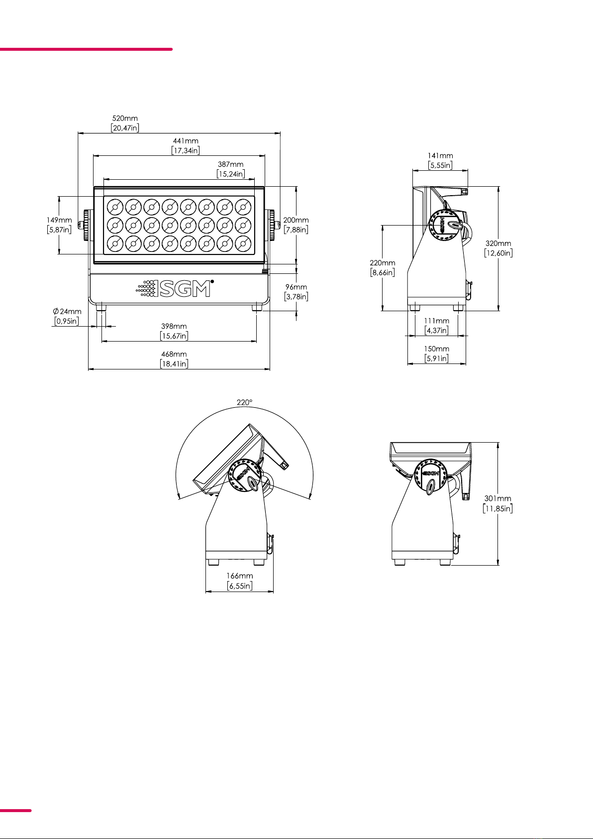
DIMENSIONS
STANDARD VERSION
All dimensions in millimeters and inches. Drawing not to scale
This manual covers installation, use, and maintenance of the P-6 SGM Series. A digital version is available at
to change without notice. SGM and all affiliated companies disclaim liability for any injury, damage, direct
or indirect loss, consequential or economic loss, or any other loss occasioned by the use of, inability to use, or
reliance on the information contained in this manual. The SGM logo, the SGM name, and all other trade-
marks in this document perwtaining to SGM services or SGM products are trademarks owned or licensed by
SGM, its affiliates, and subsidiaries. This edition applies to firmware version 2.23 or later.
English edition © 2022 SGM Light A/S®.

3Product Version 1.0 | Revision E | Released 2022-12-09
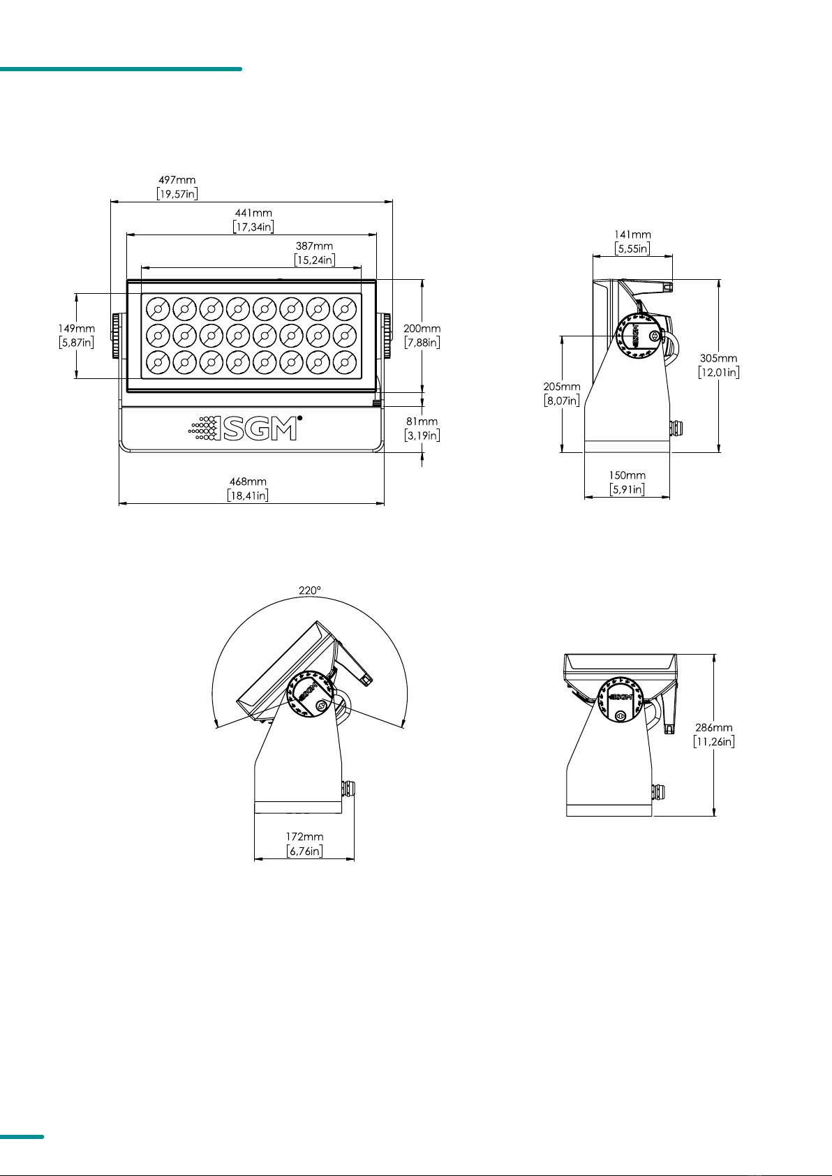
POI VERSION
All dimensions in millimetres and inches. Drawing not to scale
DIMENSIONS

4Product Version 1.0 | Revision E | Released 2022-12-09
2 DIMENSIONS
2 Standard version
3 POI version /
6 SAFETY INFORMATION
7 BEFORE INSTALLING THIS PRODUCT
8 INSTALLATION STANDARD FIXTURE
8 Identication and terminology
9 Unpacking
9 Transport handling
9 Rigging
10 Rigging process using SGM Omega brackets
11 Tilt lock
11 Power requirements
12 Connecting power
12 Connecting data
12 Connecting a wireless transmitter
12 Signal priority
13 INSTALLATION POI FIXTURE
13 Identication and terminology
14 Unpacking
14 Application considerations
14 Connecting temporary Power
15 Connecting temporary signal
16 Settings and Fixture Defaults
17 Wireless Data Connection
17 LED Indicator Behaviour
18 Mounting
18 Brackets
19 Flat Bracket attachment
19 Omega Bracket attachment
20 Universal Bracket attachment
21 Wall Bracket attachment
22 POI TIlt Lock
23 Permanently Connecting Power & Data
24 USER INTERFACE
24 Using the display panel
24 Shortcuts
25 DISPLAY
25 Operational mode (A)
25 DMX Address (B)
25 External data indicator (C)
25 External data protocol (D)
25 Error Indicator
CONTENT

5Product Version 1.0 | Revision E | Released 2022-12-09
26 CONFIGURING THE DEVICE FOR DMX CONTROL
26 About DMX
26 DMX Start address
26 Set/edit DMX address
26 Setting the DMX mode
27 SETTING A STATIC COLOR MANUALLY
27 USING STANDALONE OPERATION
28 FIXTURE PROPERTIES
28 Factory default
28 LED Engine
28 Individual xture settings
29 CONTROL MENU
31 RDM
31 Supported RDM functions
31 Sensors
32 ACCESSORIES
32 Filter frames
32 Barndoors
33 MAINTENANCE
33 SGM Vacuum Test kit
34 Firmware Updates
34 Cleaning
35 TROUBLESHOOTING
36 FIXTURES AND ACCESSORIES
36 Ordering information
37 SUPPORT HOTLINE
37 APPROVALS AND CERTIFICATIONS
38 USER NOTES
CONTENT

6Product Version 1.0 | Revision E | Released 2022-12-09
SAFETY INFORMATION
SGM fixtures are intended for professional use only. They are not suitable for household use.
Les fixtures SGM sont impropre à l’usage domestique. Uniquement à usage professionnel.
This product must be installed in accordance with the applicable installation code by a person
familiar with the construction and operation of the product and the hazards involved.
Ce produit doit être installé selon le code d’installation pertinent, par une personne qui connaît
bien le produit et son fonctionnement ainsi que les risques inhérent.
DANGER! RISK OF ELECTRIC SHOCK DO NOT OPEN THE DEVICE!
• Always power off/unplug the fixture before removing covers or dismantling the product.
• Ensure that the mains power is cut off when wiring the device to the AC mains supply.
• Ensure that the device is electrically connected to earth (ground).
• Do not apply power if the device or mains cable is in any way damaged.
• Do not immerse the fixture in water or liquid.
WARNING! TAKE MEASURES TO PREVENT BURNS AND FIRE!
• Install in a location that prevents accidental contact with the device.
• Install only in a well-ventilated space.
• Install at least 0.3 m (12 in.) away from objects to be illuminated.
• Install only in accordance with applicable building codes.
• Ensure a minimum clearance of 0.3 m (12 in.) around the cooling fans
• Do not paint, cover, or modify the device, and do not filter or mask the light.
• Keep all flammable materials well away from the device.
ALLOW THE DEVICE TO COOL FOR 15 MINUTES AFTER OPERATION BEFORE TOUCHING IT
CAUTION: EXTERIOR SURFACE TEMPERATURE AFTER 5 MIN. OPERATION = 42°C 108°F.
STEADY STATE = 48°C 118°F.
WARNING! TAKE MEASURES TO PREVENT PERSONAL INJURY. DO NOT
LOOK DIRECTLY AT THE LIGHT SOURCE FROM CLOSE RANGE.
• Take precautions when working at height to prevent injury due to falls.
• For Permanent Outdoor Installations (POI), ensure that the fixture is securely fastened to
a load-bearing surface with suitable corrosion-resistant hardware.
• For a temporary installation with clamps, ensure that the quarter-turn fasteners are
turned fully and secured with a suitable safety cable. The standard safety wire cable must
be approved for a safe working load (SWL) of 10 times the weight of the fixture, made of
a grade AISI 316 steel, and it must have a minimum gauge of 4 mm.
• For elevated installations, secure the fixture with suitable safety cables, and always com-
ply with relevant load dimensioning, safety standards, and requirements.
WARNING! READ THE FOLLOWING SAFETY PRECAUTIONS CAREFULLY BE-
FORE UNPACKING, INSTALLING, POWERING OR OPERATING THE DEVICE.

7Product Version 1.0 | Revision E | Released 2022-12-09
BEFORE INSTALLING THIS PRODUCT
Please visit the SGM official website at www.sgmlight.com for the latest version of this user
manual/ safety information leaflet. Due to continuous improvements, the instructions may
change without notice. SGM always recommends the latest available firmware version from
www.sgmlight.com.
EXTERNAL CLEANING AND VISUAL INSPECTION OF THE FIXTURE
All users of SGM luminaires should regularly clean those parts of the luminaire directly exposed
to the elements, such as the external housing and front lenses. Additionally, all owners of SGM
luminaires must periodically check the external housing of the luminaire for structural breaks,
components in bad shape, cracked lenses, or loose screws. To ensure proper operation, but also
to prevent the risk of potential accidents, do not use the luminaire if the lens, housing, or power
cables are damaged. If parts of the luminaire appear to be missing, cease use immediately and
contact SGM support.
WIRING AND CONDUIT/ CONTAINMENT
SGM luminaires supplied with power and data cable leads are not intended for installation in
permanently installed conduit or containment. When installing luminaires in a permanent in-
stallation, ensure cable leads are installed as a service loop to an appropriately rated junction
box using suitable cable strain reliefs / glands. All installed luminaires must be securely mount-
ed and service loop appropriately protected for installation location. All electrical wiring and
connections should be completed by a qualified electrician.
SAFETY PRECAUTIONS
When using electrical equipment, basic safety precautions should always be followed including
the following:
• Do not mount near gas or electric heaters.
• Permanently installed equipment should be mounted in locations and at heights where
it will not readily be subjected to tampering by unauthorized personnel.
• The use of accessory equipment not recommended by the manufacturer may cause an
unsafe condition.
• Do not use this equipment for other than intended use.
• Refer service to qualified personnel or authorized service centers.
• Do not look directly into the beam for long periods of time, when the fixture is on.
• The luminaire shall, under no circumstance, be covered with insulating material of any
kind.
READ AND FOLLOW ALL SAFETY INSTRUCTIONS.

8Product Version 1.0 | Revision E | Released 2022-12-09
INSTALLATION STANDARD FIXTURE
Illustrations might vary from received products. This is subject to change without notice.
IDENTIFICATION AND TERMINOLOGY
B
A
A: 24 x RGBW LEDs
B: Tilt lock
C: Cooling fans
D: Control panel
E:
OLED Display
F: Rubber feet
G: GORE-TEX membrane
H: DMX in and out
I: Power in and out
J: Handle
K: Barndoors attachment points
L: Safety wire attachment point
M: Holes for Omega bracket / M-10 screws (x6)
C
B
I
H
LM
G
DE
J
K
P 6
F

9Product Version 1.0 | Revision E | Released 2022-12-09
UNPACKING
Unpack the device and inspect it to ensure that it has not been damaged during transport.
The fixture is shipped with:
• 2 x Omega bracket with 1/4-turn fasteners (standard only).
• 1 x Power cable with IP connector, 2 m./ 78 in
• Safety information leaflet.
• Application considerations
APPLICATION CONSIDERATIONS
The standard fixture is IP65-rated and is designed for both indoor and outdoor events. This means that it is protected
from:
• Dust, to the degree that dust cannot enter the fixture in sufficient quantities as to interfere with its operation.
• Lower pressure water jets from any direction.
When using standard fixtures outdoors or in wet locations, ensure that:
• The DMX connection out of the last fixture in a chain is properly sealed, in accordance with the ingress protec-
tion (IP) requirements.
• The DMX out of the last fixture is terminated with a 120 Ohm resistor between pin 2 and 3 (as per RS485 stand-
ards).
When selecting a location for the device, ensure that:
• It is situated away from public thoroughfares and protected from contact with people.
• It has adequate ventilation.
• It is not immersed or submerged in water.
TRANSPORT HANDLING
Always use the supplied packaging or suitable flight case for transportation and storage. Never carry the fixture by
connected cables or wires.
The fixture may be installed in any orientation, on the ceiling or on a
wall surface.
When installed horizontally with a downward beam-angle, water or dirt
can potentially pool in the fan wells. Under normal operation the mois-
ture will evaporate.
In locations with high rainfall, consider locating the fixture under cover
or an overhang, or modify the position and orientation of the fixture to
minimize pooling.
All SGM fixtures have locking points in the base for installation and rig-
ging. In both standard and POI fixtures, the distance between the
points from center to center is always 106 mm. Standard versions in-
clude 1/4 turn fasteners to mount SGM omega brackets. POI versions
come with M-10 captive nuts for M-10 screws.
Always use the supplied omega bracket to rig a standard fixture. Lock
the bracket with the 1/4-turn fasteners.
PLEASE NOTE! 14TURN FASTENERS ARE ONLY LOCKED WHEN TURNED FULLY CLOCKWISE. DEPENDING ON
THE STRUCTURE, PLEASE USE APPROPRIATE AND SECURE METHODS FOR MOUNTING THE OMEGA BRACKETS.
RIGGING
106 mm
[ 4,2in ]
Ø 18 mm
[ 0,7in ]
Figure 1: Locking points

10 Product Version 1.0 | Revision E | Released 2022-12-09
RIGGING PROCESS USING SGM OMEGA BRACKETS
Start the standard rigging process by blocking the lower working area, and make sure the work is performed from a
stable platform.
1. Check that the clamp/bracket is undamaged. Supporting structure should be capable of bearing at least 10
times the weight of all installed fixtures, lamps, cables etc.
2. Bolt a clamp or bracket securely to the omega bracket with a M12 bolt (min. grade 8.8) and a lock nut. For
longer term installations, choose outdoor rated hardware.
3. Align the omega bracket with the fixture base. For standard Omega Bracket, insert the fasteners into the fix-
ture base bracket, and turn both levers a full 1/4 turn clockwise to lock. When using the POI Omega Bracket,
insert the included M-10 screws through the bracket holes and tighten them with a M-10 key until they are
Figure 3.1 : Installing the P-6 Figure 3.2 : Installing the P-6
Figure 2: Dimensions for base locking points
WARNING! ALWAYS USE MIN. 2 OMEGA BRACKETS WHEN RIGGING THE FIXTURE.
Omega bracket
Holes for omega bracket
159mm
6,26in
106mm
4,17in
401mm
15,77in
111mm
4,37in
159mm
6,26in

11 Product Version 1.0 | Revision E | Released 2022-12-09
fully attached to the base.
4.Hang the fixture on a truss or other structure. Tighten the clamp/bracket.
5. Verify that there are no combustible materials, cables, or surfaces to be illuminated within 0.3 m (12 in.) of the
fixture.
6. Check that there is no risk of the head/yoke colliding with other fixtures or structures.
Fasten a safety wire (not shown) between the load-bearing support
structure and the safety wire attachment point on the device.
• The safety cable (not included in the package) must:
• Bear at least 10 times the weight of the device (SWL).
• Have a minimum gauge of 4 mm.
• Have a maximum length (free fall) = 30 cm (12 in.).
Figure 4: Safety wire attachment point
The fixture head can pivot through 120 .
To adjust the tilt angle in standard versions:
• Loosen the two tilt wing-screws (one on each side) by turning
them counter-clockwise.
• Tilt the fixture to the angle desired and hold it.
• Lock the position by re-tightening both tilt lock screws clock-
wise.
CAUTION!
ALWAYS LEAVE A FIXTURE TO COOL OFF FOR 15 MIN
UTES AFTER OPERATION BEFORE HANDLING.
Figure 5: Standard tilt lock
TILT LOCK
POWER REQUIREMENTS
The fixture can operate on any 100–277 V, 50/ 60 Hz AC mains power supply, and draws a maximum of 630 W.
Connect the fixture to AC power by installing a power connector to the bare end side of the supplied power cable.
Connect the powercon twist-lock connector side to the fixture. The fixture must be grounded/earthed and be able to
be isolated from AC power. The AC power supply must incorporate a fuse or circuit breaker for fault protection.
WARNING! ALWAYS SECURE AN ELEVATED FIXTURE WITH A SAFETY WIRE.
ALWAYS USE A SAFETY WIRE OF A GRADE AISI 316 STEEL. MAKE SURE THE
SLACK OF THE SAFETY WIRE IS AT A MINIMUM. NEVER USE THE YOKE/HAN-
DLE FOR SECONDARY ATTACHMENT.
Pitch angle
indicator

12 Product Version 1.0 | Revision E | Released 2022-12-09
CONNECTING POWER
The power cable color coding is given in figure 6:
• Connect the black wire to live
• Connect the white wire to neutral (or phase 2 on 208V
supplies)
• Connect the green/yellow wire to ground (earth)
For a temporary outdoor installation the mains cable must be fitted with a grounded connector intended for exterior
use.
For permanent installations, a qualified electrician must wire the mains cable directly to a suitable branch circuit and
as per local code. The junction’s ingress protection (IP) rating must be suitable for the location. Always use a junction
box with a proper IP class suitable for the environment.
After connecting the fixture to power, run the on-board test by selecting the option “TEST→ SELFTEST” in the menu,
to ensure that the fixture and each LED are functioning correctly. (POI versions are tested through RDM.)
PLEASE NOTE! THE PROTECTIVE CAPS MUST BE SECURELY MOUNTED ON ANY UNUSED CONNECTORS, IN OR
DER TO MAINTAIN INGRESS PROTECTION IP RATING.
CAUTION!
DO NOT CONNECT THE FIXTURE TO AN ELECTRICAL DIMMER SYSTEM, AS DOING SO MAY
CAUSE DAMAGE
CONNECTING DATA
The fixture is controllable using a DMX control device, and it can be connected using either a DMX cable, or via the
fixture’s built-in CRMX wireless receiver system.
When using a cabled DMX system, connect the DMX-In cable to the input connector and DMX-Out cable to the out-
put, both on the rear of the fixture’s base (chassis mounted male and female 5-pin XLR plugs). For outdoor installa-
tions, use only IP-rated XLR connectors suitable for outdoor use. Terminate the DMX out cable of the last fixture in the
data link with a 120 ohm DMX termination.
Note that SGM fixtures provide a passive DMX Thru signal as DMX Out, instead of an active output signal.
PLEASE NOTE! FOR POI VERSIONS, PLEASE REFER TO “INSTALLATION POI FIXTURE”
CONNECTING A WIRELESS TRANSMITTER
The fixture is designed to look for wireless transmitters in ‘connect’ state when this option is not yet enabled. The fix-
ture comes tested for wireless functionality from the factory, therefore the beginning of the pairing process is discon-
nect from the factory wireless DMX transceiver.
To connect the fixture to a wireless transmitter:
1. Log off the currently paired wireless transmitter. Go to SETTINGS → WIRELESS DMX → LOG OFF in the menu.
Fixture confirms logged off.
2. Press the connect button on the wireless transmitter.
3. Confirm that the fixture has paired with the wireless transmitter.
PLEASE NOTE! FOR POI VERSIONS, REFER TO “"WIRELESS DATA CONNECTION" ON PAGE 17” .
SIGNAL PRIORITY
The fixture can be paired to an active wireless transmitter while also being connected to a cabled DMX signal. By de-
fault, the fixture will prioritize cabled DMX over wireless DMX. Through the Settings menu in the display or RDM, this
can be changed so that the fixture will prioritize the wireless DMX signal over cabled DMX.
The active input type is displayed under the wireless signal strength indicator. The signal strength can be also checked
via RDM data by using an external RDM device.
PLEASE NOTE! IN POI VERSION WITH WIRELESS, THE DMX SIGNAL STRENGTH IS CHECKED THROUGH RDM.
Color
Black
White
green/yellow
Conductor
live
neutral
ground (earth)
Symbol
or
L
N
Wire
(L2)
Figure 6: Connecting AC Power/P-1 power cable 8 mm

13 Product Version 1.0 | Revision E | Released 2022-12-09
INSTALLATION POI FIXTURE
IDENTIFICATION AND TERMINOLOGY
Illustrations might vary from received products. This is subject to change without notice.
A
A: 24 x RGBW LEDs
B: POI Tilt lock
C: Cooling fans
D: LED indicator
E: GORE-TEX membrane
F: DMX in and out
G: Power in and out
H: Handle
I: Barndoors attachment points
J: Safety wire attachment point
K: Holes for Omega bracket / M-10 screws (x6)
B
B
G
F
JK
E
D
H
I
C
P 6

14 Product Version 1.0 | Revision E | Released 2022-12-09
PLEASE NOTE! POI FIXTURES SHOULD BE PRESET WITH ANY CUSTOM PROGRAMMING BEFORE INSTALLATION.
ALTHOUGH MOST FUNCTIONS ARE POSSIBLE TO BE SET VIA RDM ONCE MOUNTED IN POSITION, IT IS EASIER
TO DO CONFIGURATION AND ANY TROUBLESHOOTING BEFORE MOUNTING IS COMPLETE.
UNPACKING
Unpack the device and inspect it to ensure that it has not been damaged during transport.
Thefixture is shipped with:
• 1 x Spanner with magnet (POI version).
• 6 x M-10 screws (POI version).
• power cable with bare ends
• Safety information leaflet
APPLICATION CONSIDERATIONS
The POI fixture is IP66-rated and designed for use in outdoor installations. This means that it is protected from:
• Dust, to the degree that dust cannot enter the device in sufficient quantities as to interfere with its operation.
• High pressure water jets from any direction.
CONNECTING TEMPORARY POWER
Connect to AC power using the supplied 8mm cable (the larger of the two permanently wired cables). The fixture
must be grounded/earthed. The AC power supply must incorporate a fuse or circuit breaker for fault protection. For
temporary programming, a plug or terminals can be used.
The power cable color coding is shown to the left:
• Connect the black wire to live
• Connect the white wire to neutral
• Connect the green/yellow wire to ground (earth)
Figure 7: Connecting AC Power
The fixture must be grounded/
earthed and be able to be isolated
from AC power. The AC power
supply must incorporate a fuse or
curcuit breaker for fault protection.
Color
Black
White
green/yellow
Conductor
live
neutral
ground (earth)
Symbol
or
L
N
Wire

15 Product Version 1.0 | Revision E | Released 2022-12-09
Figure 9: Connecting data to USB up-loader cable for POI fix-
tures
Figure 8: Data wiring guide for setup
CONNECTING TEMPORARY SIGNAL
The fixture is compatible with DMX512 (ANSI E1.11 – 2008) only. It can be connected using either the SGM POI up-load-
er cable, or via the fixture’s built-in CRMX wireless receiver system.
STEP 1: Download and install the SGM RDM Addressing tool.
< https://sgmlight.com/products/rdm-addressing-tool >
STEP 2: Connect the bare end data cable to the POI Up-loader cable for POI fixtures.
STEP 3: Connect the USB up-loader cable for POI fixtures to a computer with a USB Type-A port.
Step 5 Disconnect up-loader cable from computer, then disconnect up-loader cable from fixture.
Repeat Steps 2-5 for more fixtures. Multiple fixtures can be addressed and configured. Contact your SGM representa-
tive for more information on multiple fixture addressing.
PLEASE NOTE! AT A MINIMUM, ALL FIXTURES WILL NEED TO BE GIVEN A DMX ADDRESS AND DMX PERSONALI
TY IN ORDER TO PATCH AND PROGRAM ON A CONTROLLER. REFER TO MANUALS FOR MORE DETAILS.

16 Product Version 1.0 | Revision E | Released 2022-12-09
SETTINGS AND FIXTURE DEFAULTS
All configuration of POI fixtures is done through the SGM Addressing Tool. The SGM Addressing Tool is a windows
based program designed to allow the user to configure the fixture through the RDM protocol. All settings on a stan-
dard fixture are available on a POI fixture. But on POI, these settings are changed through the Addressing Tool.
STEP 1: Launch SGM RDM Addressing Tool. Click Full Discovery and look for the green light to illuminate on the fixture.
If the green light does not appear, cycle power or refer to troubleshooting.
STEP 2: Select the standard settings tab and enter a DMX address and a personality/mode of operation. These modes
must match the control mode in the controller which will control the fixture. Look for the LED indicator to blink to
confirm setting change. DMX modes for POI and Std versions are identical. Refer to CONFIGURING THE DEVICE later
in this manual for specifics for more information on fixture functions. Visit www.sgmlight.com to see all DMX charts
STEP 3: If necessary for the application, click advanced settings to set the fan mode, dimming curve, calibration or to
reset to factory defaults.
STEP 4: Disconnect POI Uploader cable.
Repeat as required for multiple fixtures.
Factory Defaults are as follows:
• Set DMX address to 1
• Set 6 Channel CTC DMX mode
• Set screensaver to Dimmed
• Set flip screen to not-flipped
• Disable Startup Programs
• Set all Quick Color values to zero
• Disable DMX Loss
• Disable Fast Speed mode
• Set all values in Manual Programs to zero
• Set Fan mode to Standard
• Disabled Keypad Lock
• Set Wireless Priority to DMX
• Set Custom Frequency to Default
Figure 10: SGM Addressing tool

17 Product Version 1.0 | Revision E | Released 2022-12-09
LED INDICATOR BEHAVIOUR
The fixture displays the status of connections, setting and errors through the LED indicator. It can have different colors
and three possible stages: static, flashing, or off.
Once configuration is complete, temporary power and data can be disconnected.
• Solid Orange: Fixture is starting up.
• Blinking Green: Wireless and/or wired DMX is connected and no errors.
• Solid Green: No wireless and/or wired DMX connection and no errors.
• Blinking Green-Orange: Error(s) have occurred and no wireless and/or wired DMX connection
• Solid Orange: Error(s) have occurred and wireless and/or wired DMX is connected.
• Blinking Orange: Hall sensor is activated. When activated more than 3 seconds wireless DMX connection is
logged off.
In POI fixtures with wireless, it is necessary to pair the fix-
ture with a new transmitter (by default, the fixture is
linked to the SGM factory transmitter during the testing
and QA process).
In order to do so, make sure the fixture is powered on be-
fore taking the following steps:
STEP 1: Using a SGM magnetic spanner tool, place the
magnet close to the LED indicator, and wait for 3 seconds.
The LED indicator will blink orange for 1-2 seconds, before
switching to static green again. The fixture can now be
paired to a new transmitter.
STEP 2: Select “connect” or “link” on a wireless DMX trans-
mitter. The transmitter and the internal SGM receiver
should now be linked together.
Repeat the process to link the fixture to another transmit-
ter.
To disconnect the fixture from the currently paired wireless transmitter, hold the magnet for 3 seconds over the LED
indicator. The LED indicator will blink orange for 1-2 seconds, switching later to green again. The fixture is now logged
off.
WIRELESS DATA CONNECTION
PLEASE NOTE! REMOTE DEVICE MANAGEMENT RDM REQUIRES A CORRECTLY INSTALLED AND TERMINATED
DMX CABLE.
When setting addresses through RDM and using USB dongles, it may be necessary to disable “USB selective sus-
pend”
to ensure a proper voltage to the DMX link. If any lag or trouble occurs when addressing, decrease the cable
length range to <12 m. and only address one fixture at a time.
Figure 11: POI Spanner

18 Product Version 1.0 | Revision E | Released 2022-12-09
MOUNTING
All SGM POI fixtures have M10 size attachment points to mount the supplied brackets or directly to a structure.
The POI wash fixture may be installed in any orientation and it might take up to two brackets per fixture. Depending
on the structure, please use appropriate and secure methods for mounting the Omega brackets.
Figure 12: POI base with dimensions
Flat bracket Omega bracket
Wall mount bracket
Universal bracket
BRACKETS
There are four bracket choices available from SGM:

19 Product Version 1.0 | Revision E | Released 2022-12-09
FLAT BRACKET ATTACHMENT
OMEGA BRACKET ATTACHMENT
M10 Countersunk Bolts
Flat Bracket
8mm or smaller screw
or bolt to structure
8mm or smaller screw
or bolt to structure
Fixture
13mm / 0.5in hole diameter
for attachment point
M10 Stainless Steel Bolts
POI Omega Bracket
Fixture
Figure 13: POI Base flat bracket attachment
Figure 14: POI Base omega bracket attachment

20 Product Version 1.0 | Revision E | Released 2022-12-09
UNIVERSAL BRACKET ATTACHMENT
PLEASE NOTE! THE UNIVERSAL BRACKET HAS DIFFERENT SLOT CURVES FOR 68 SERIES FIXTURES AND 10
SERIES FIXTURES. WHEN ATTACHING THE BRACKET TO THE FIXTURE, MAKE SURE THE SLOT WITH “68 SERIES”
LABEL IS FACING AWAY FROM THE CENTER OF THE FIXTURE. BOLTS TO MOUNTING SURFACE WILL USE THIS
SLOT.
M10 Countersunk Bolts
POI Universal Bracket
Fixture
Using a bolt through this slot,
the fixture will rotate around its
center point, always use 2 bolts
with washers.
Using a bolt through this slot,
the fixture will rotate around its
center point, always use 2 bolts
with washers.
Figure 15: POI Base Universal bracket attachment
Other manuals for P-6
1
Table of contents
Other SGM Lighting Equipment manuals

SGM
SGM IDEA SCANNER 250 User manual

SGM
SGM Giotto spot 400 User manual

SGM
SGM LB-100 User manual

SGM
SGM X Line IDEA WASH 575 User manual

SGM
SGM Q-8 User manual

SGM
SGM Flasher DMX 1.5 User manual

SGM
SGM Giotto WASH 1200 User manual

SGM
SGM P Series User manual

SGM
SGM Q?7 User manual

SGM
SGM Hazer 400 User manual