SGM VPL Series User manual

USERMANUAL
LED VIDEO PIXEL LINEAR
Product Version 1.0 | Document Revision D | Released 2023-01-10
This manual covers installation, use, and maintenance of the SGM LED Video Pixel Linear. A digital version is
ment is subject to change without notice. SGM and all affiliated companies disclaim liability for any injury,
damage, direct or indirect loss, consequential or economic loss, or any other loss occasioned by the use of,
inability to use, or reliance on the information contained in this manual. The SGM logo, the SGM name, and
all other trademarks in this document pertaining to SGM services or SGM products are trademarks owned
or licensed by SGM, its affiliates, and subsidiaries. This edition applies to firmware version 2.23 or later.
English edition © 2022 SGM Light A/S®.

2Product Version 1.0 | Revision D | Released 2023-01-10
1212mm
47,717in
1180mm
46,457in
48,969in
1243,80mm
63,29mm
2,492in
1307,09mm
51,460in
63,15mm
2,49in
623,90mm
24,56in
687,05mm
27,05in
313,90mm
12,36in
63,15mm
2,49in
377,05mm
14,84in
602,40mm
23,72in
570,40mm
22,46in
297,60mm
11,72in
265,60mm
10,46in
38mm
1,496in
51,58mm
2,031in
DIMENSIONS
All dimensions in millimetres and inches. Drawing not to scale

3Product Version 1.0 | Revision D | Released 2023-01-10
2 DIMENSIONS
4 SAFETY INFORMATION
5 BEFORE INSTALLING THIS PRODUCT
6 OVERVIEW
6 VPL Series
6 VPL variants
7 INSTALLATION
7 Identifying power & data
7 Unpacking
7 Application considerations
7 Transport handling
8 Rigging process using SGM brackets
9 Temporary installations
9 Safety wires
10 Frames
11 GROUNDING OF FIXTURES
11 Installing ground wire
12 CONNECTING THE VPL SERIES
12 Permanently Connecting Power & Data
12 VPL Power & Data Joiner
13 Connect to AC power
14 Cable lengths
15 VP Connector
15 INSTALLING THE FIXTURES
15 Mounting
17 Replacing a xture / De-mounting
18 Replacing
18 VPL NETWORKING GUIDE
19 Network Setup
20 Universal Datagram Packet (UDP)
20 Network Size
20 FIXTURE PROPERTIES
20 Factory default
21 LENSES AND LENS ACCESSORIES
22 Removing a lens
22 Cutting a VPL lens
23 Factory Default with magnet
23 MAINTENANCE
23 Upgrading the rmware
23 Cleaning
24 FIXTURES AND ACCESSORIES
24 Ordering information
24 VPL Lenses
25 SUPPORT HOTLINE
25 APPROVALS AND CERTIFICATIONS
26 USER NOTES
CONTENT

4Product Version 1.0 | Revision D | Released 2023-01-10
SAFETY INFORMATION
SGM fixtures are intended for professional use only. They are not suitable for household use.
Les fixtures SGM sont impropre à l’usage domestique. Uniquement à usage professionnel.
This product must be installed in accordance with the applicable installation code by a person
familiar with the construction and operation of the product and the hazards involved.
Ce produit doit être installé selon le code d’installation pertinent, par une personne qui connaît
bien le produit et son fonctionnement ainsi que les risques inhérent.
DANGER! RISK OF ELECTRIC SHOCK DO NOT OPEN THE DEVICE!
• Do not open the device; there are no user-serviceable parts inside.
• Ensure that power is cut off when wiring the device to the AC mains supply.
• Ensure that the device is electrically connected to earth (ground).
• Do not apply power if the device or mains cable is in any way damaged.
• Do not immerse the fixture in water or liquid.
WARNING! TAKE MEASURES TO PREVENT BURNS AND FIRE!
• Install in a location that prevents accidental contact with the device.
• Install only in a well-ventilated space.
• Install only in accordance with applicable building codes.
• Do not paint, cover, or modify the device, and do not filter or mask the light.
• Keep all flammable materials well away from the device.
ALLOW THE DEVICE TO COOL FOR 15 MINUTES AFTER OPERATION BEFORE TOUCHING IT
CAUTION: EXTERIOR SURFACE TEMPERATURE AFTER 5 MIN. OPERATION = 42°C 108°F.
STEADY STATE = 48°C 118°F.
WARNING! TAKE MEASURES TO PREVENT PERSONAL INJURY. DO NOT
LOOK DIRECTLY AT THE LIGHT SOURCE FROM CLOSE RANGE.
• Take precautions when working at height to prevent injury due to falls.
• For Permanent Outdoor Installations (POI), ensure that the fixture is securely fastened
to a load-bearing surface with suitable corrosion-resistant hardware.
• For a temporary installation the standard safety wire cable must be approved for a safe
working load (SWL) of 10 times the weight of the fixture, made of grade AISI 316 steel,
and it must have a minimum gauge of 3mm.
• For elevated installations, secure the fixture with suitable safety cables, and always
comply with relevant load dimensioning, safety standards, and requirements.
WARNING! READ THE FOLLOWING SAFETY PRECAUTIONS CAREFULLY BE-
FORE UNPACKING, INSTALLING, POWERING OR OPERATING THE DEVICE.

5Product Version 1.0 | Revision D | Released 2023-01-10
BEFORE INSTALLING THIS PRODUCT
Please visit the SGM official website at www.sgmlight.com for the latest version of this user
manual/ safety information leaflet. Due to continuous improvements, the instructions may
change without notice. SGM always recommends the latest available firmware version from
www.sgmlight.com.
EXTERNAL CLEANING AND VISUAL INSPECTION OF THE FIXTURE
All users of the SGM fixtures should regularly clean those parts of the fixture directly exposed
to the elements, such as the external housing and front lenses. Additionally, all owners of the
SGM fixtures must periodically check the external housing of the fixture for structural breaks,
deterioration, cracked lenses, or loose screws. To ensure proper operation, but also to prevent
the risk of potential accidents, do not use the fixture if the lens, housing, or power cables are
damaged. If parts of the fixture appear to be missing, cease use immediately and contact SGM
support.
WIRING AND CONDUIT/ CONTAINMENT
SGM fixtures supplied with power and data cable leads are not intended for installation in
permanently installed conduit or containment. When installing the fixtures in a permanent
installation, ensure cable leads are installed as a service loop to an appropriately rated junction
box using suitable cable strain reliefs/glands. All installed fixtures must be securely mounted,
and service loop appropriately protected for installation location. All electrical wiring and
connections should be completed by a qualified electrician.
SAFETY PRECAUTIONS
When using electrical equipment, basic safety precautions should always be followed includ-
ing the following:
• Do not mount near gas or electric heaters.
• Permanently installed equipment should be mounted in locations and at heights
where it will not be readily subjected to tampering by unauthorized personnel.
• The use of accessory equipment not recommended by the manufacturer may cause an
unsafe condition.
• Do not use this equipment for other than intended use.
• Refer service to qualified personnel or authorized service centers.
• Do not look directly into the beam for long periods of time, when the fixture is on.
• The fixture shall, under no circumstance, be covered with insulating material of any
kind.
READ AND FOLLOW ALL SAFETY INSTRUCTIONS.

6Product Version 1.0 | Revision D | Released 2023-01-10
OVERVIEW
The VPL Series is a group of "Video Pixel Linear" fixtures. Each VPL is an array of LED Quad-Pixel clusters inde-
pendently controlled, designed to create powerful pixel mapping and media effects for both indoor and outdoor
installations. The fixture is a perfect lighting fixture for linear and radial installations where high-visibility and very
flexible setup are essential.
VPL SERIES
• Is an all-weather IP-66-rated fixture.
• Has 16, 32 or 64 full-color LED Quad-Pixel clusters.
• Is IK09-rated, C-5M / CX (marine) protected, UV and corrosion resistant.
• Uses Power and Data in one cable with no need for external power supplies or drivers.
• Is Art-Net and sACN compatible.
• Has 16 bit control with real time remote monitoring and auto addressing.
• Is available in different lengths, with optional front lenses as and accessories.
VPL VARIANTS
There are three available lengths of the VPL:
VPL SIZE LED QUAD PIXEL
1220-20 1220mm. / 4 ft. 64 Quad pixel clusters
256 full-color LED chips
610-20 610mm. / 2 ft. 32 Quad pixel clusters
128 full-color LED chips
305-20 305mm. / 1 ft. 16 Quad pixel clusters
64 full-color LED chips
7Product Version 1.0 | Revision D | Released 2023-01-10
INSTALLATION
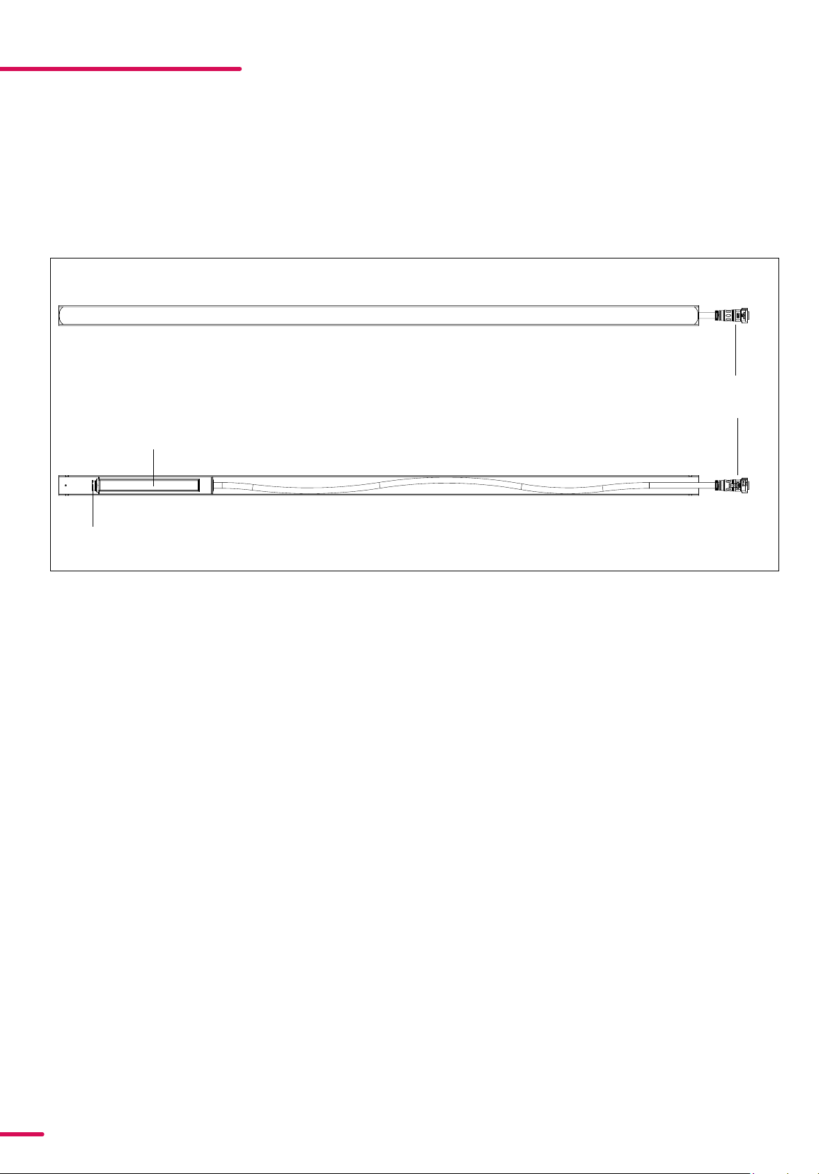
IDENTIFYING POWER & DATA
The VP cable with the male connector is the flexible cable which extends from the power supply, while the female
VP data connector is mounted directly into the power supply (see figure 1).
Female VP Power + Data connector
Male VP Pow
er +
Data connector
Power supply
Figure 1: Identifying Power + Data
UNPACKING
Unpack the device and inspect it to ensure that it has not been damaged during transportation.
APPLICATION CONSIDERATIONS
The fixture is IP66-rated and designed for both indoor and outdoor events, which completely protects the fixture
from:
• Dust: to the degree that dust cannot enter the device in sufficient quantities to interfere with its operation.
• High pressure jets of water from any direction.
When selecting a location for the device, ensure that:
• It is situated away from public thoroughfares and protected from contact with people.
• It is not immersed in water.
• It has adequate ventilation.
VPL Connector End cap:
• Ensure that the last fixture's has a waterproof VPL Connector End cap installed in the female chassis connec-
tor, to maintain the IP66 rating
TRANSPORT HANDLING
• Always use the supplied packaging or suitable flight case for transportation and storage.
• Never carry the fixture by connected cables or wires!
8Product Version 1.0 | Revision A | Released 2023-01-10
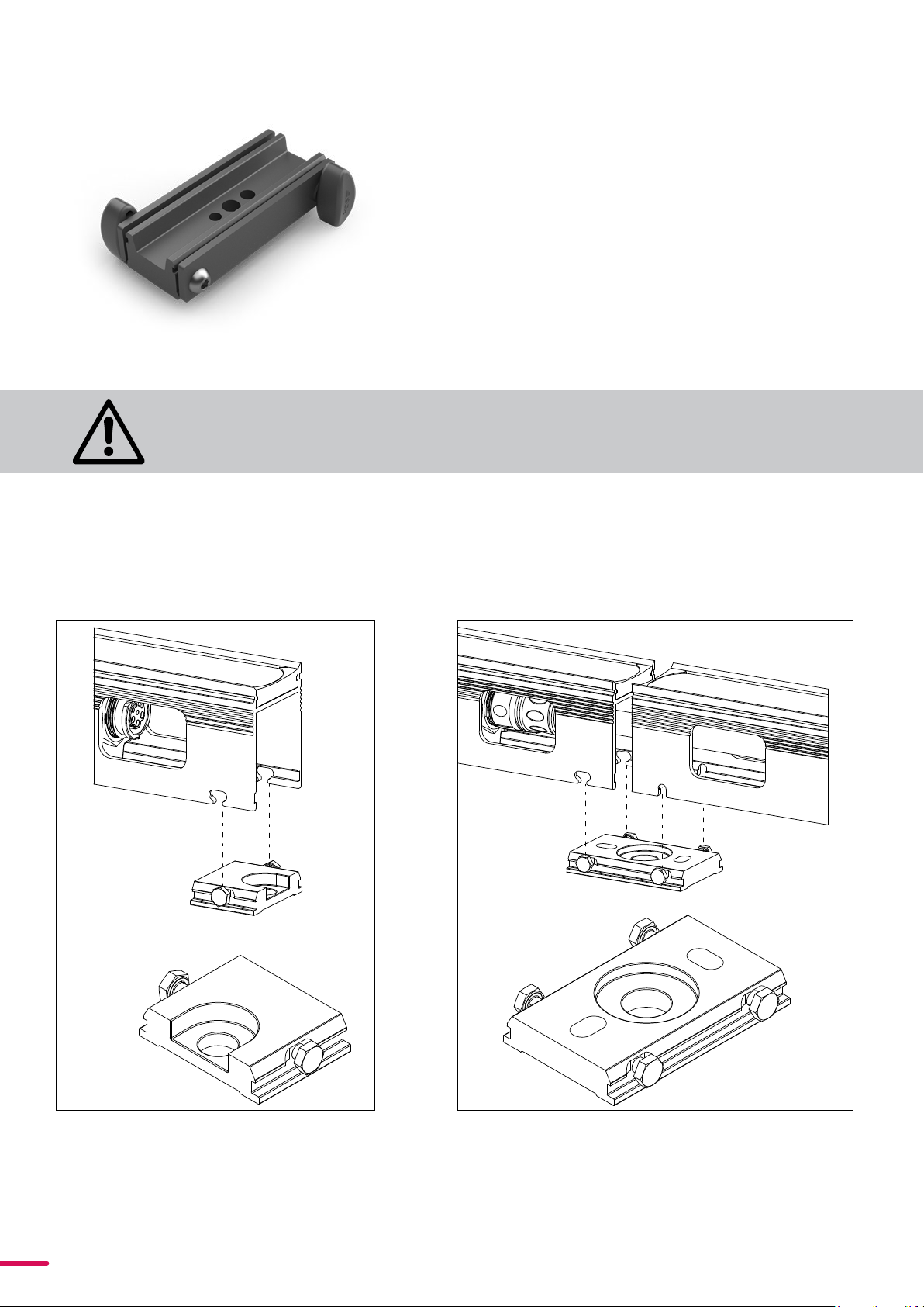
SGM offers three brackets for installation of VPLs: The
touring bracket for temporary setups and single or dual
bracket for permanent installations.
The VPL Touring Bracket (P/N: 83060633) (see figure 2) is
perfect for temporary installations. It has a snap-on sliding
bracket for quick release and easy setup, designed as a
versatile item to attach a generic third-party clamp for
rigging the VPLs. When using touring brackets, always
secure every VPL with a safety wire, attached to the
fixture's highest point.
The choice of permanent installation brackets depends on
the VPL setup.
Figure 3: Single bracket Figure 4: Dual bracket
Figure 2: VPL Touring Bracket
The Single Installation Bracket (P/N: 86060634) is
intended for single ends of VPLs, arranged in a
parallel array (see figure 3)
RIGGING PROCESS USING SGM BRACKETS
Single Bracket
Dual Bracket
The VPL Dual Installation Bracket (P/O: 83060635) is
intended for installing the fixtures in a physical series
connection (see figure 4). The VPL Dual Installation
Bracket will maintain the pixel pitch of 20mm and can be
used in combination with the touring bracket to ensure a
consistent distance between pixels.
PLEASE NOTE! UNDERSTANDING AND CHOOSING THE RIGHT BRACKET IS CRUCIAL FOR SAFETY. FOR PERMA
NENT INSTALLATIONS, THE VPLS SHOULD ALWAYS BE MOUNTED WITH AT LEAST TWO BRACKETS.
ALWAYS SECURE EVERY VPL WITH A SAFETY WIRE WHEN USING THE VPL
TOURING BRACKET.
9Product Version 1.0 | Revision A | Released 2023-01-10
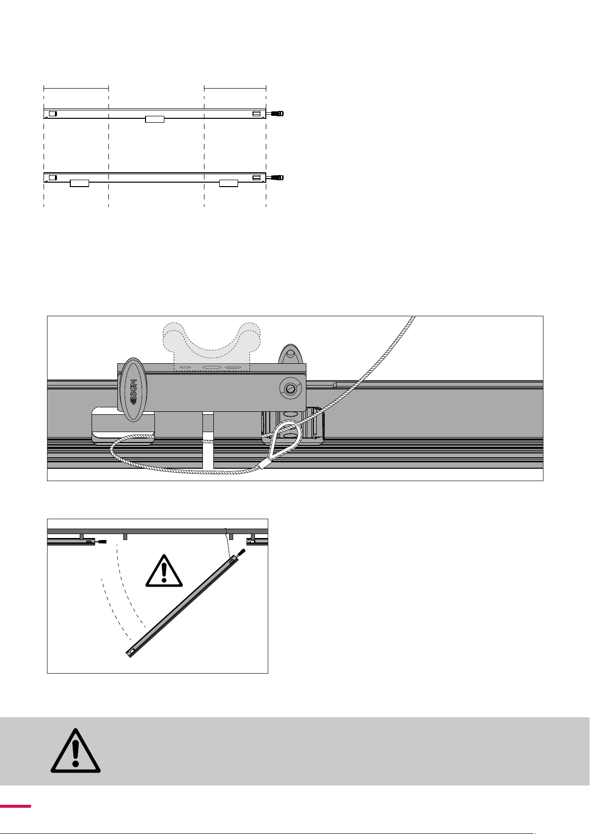
TEMPORARY INSTALLATIONS
The Touring Bracket is designed for temporary
installations and rental applications. It is a
versatile bracket, meant for attachment to truss
or pipes. A VPL Single Touring bracket can carry a
SGM VPL 1220-20 if it is placed no more than 300
mm away from either end of a VPL. (see figure 5).
Figure 5: Bracket guide-line, if the bracket is closer to than
300mm to the edge, two brackets are advised.
SAFETY WIRES
The safety wire should be installed at the highest
point on the VPL to minimize the fall distance.
When installing VPLs in ceilings or any horizontal
plane with people below, make sure to install one
safety wire in both ends of the VPL (see figure 7). If
the fixtures are installed as an extension of each
other, one safety wire can be attached to two
adjacent fixtures (see figure 6).
Attach to suitable truss
Figure 7: Attach the safety wire in both sides.
Figure 6: Attaching safety wire through the holes in the VPL
profiles.
WARNING! ALWAYS INSTALL A SAFETY WIRE ON BOTH ENDS WHEN
USING VPLS IN A CEILING INSTALLATION. THE VPLS SHOULD ALWAYS BE
PROPERLY FIXED AND NOT HUNG IN THE CABLES.
one bracket
two brackets
300mm 300mm
10 Product Version 1.0 | Revision A | Released 2023-01-10
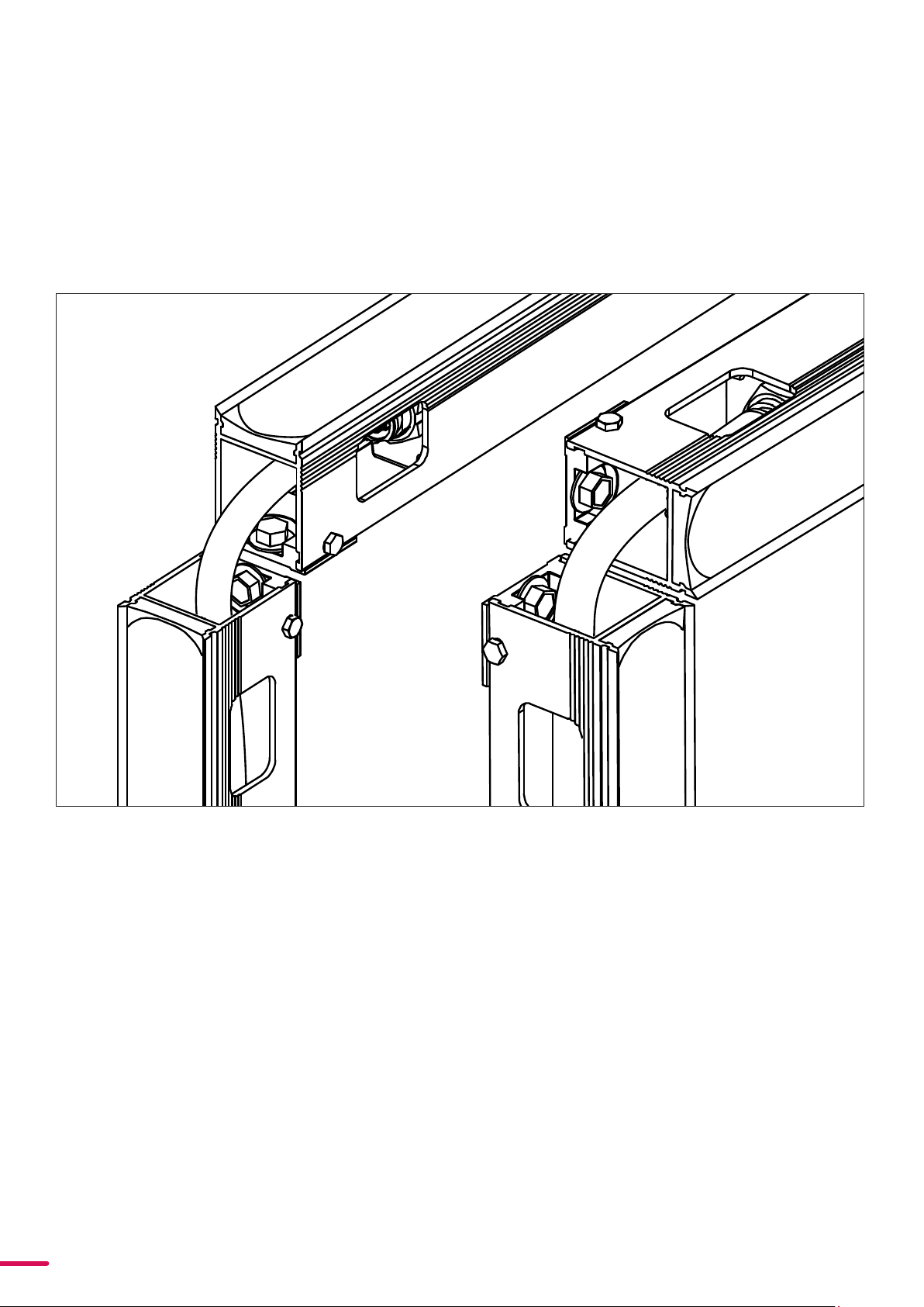
FRAMES
To create frames and shapes with the VPLs, install the fixtures with enough space for the VP cable to attach to the
next VPL. Figure 8 illustrates the two recommended orientations of the standard VPL 1220-20 and 610-20. Note that
the VPL 305-20 cannot bend a full 90 degree due to the compactness of the fixture's cable. Make sure the installa-
tion is rigid so that the fixtures cannot move and cause extensive wear on the cables. For further information or
suggestions about the VLP and their installation, please contact your local SGM distributor or SGM support at
Figure 8: Orientations of a corner lying flat or sideways.
11 Product Version 1.0 | Revision D | Released 2023-01-10
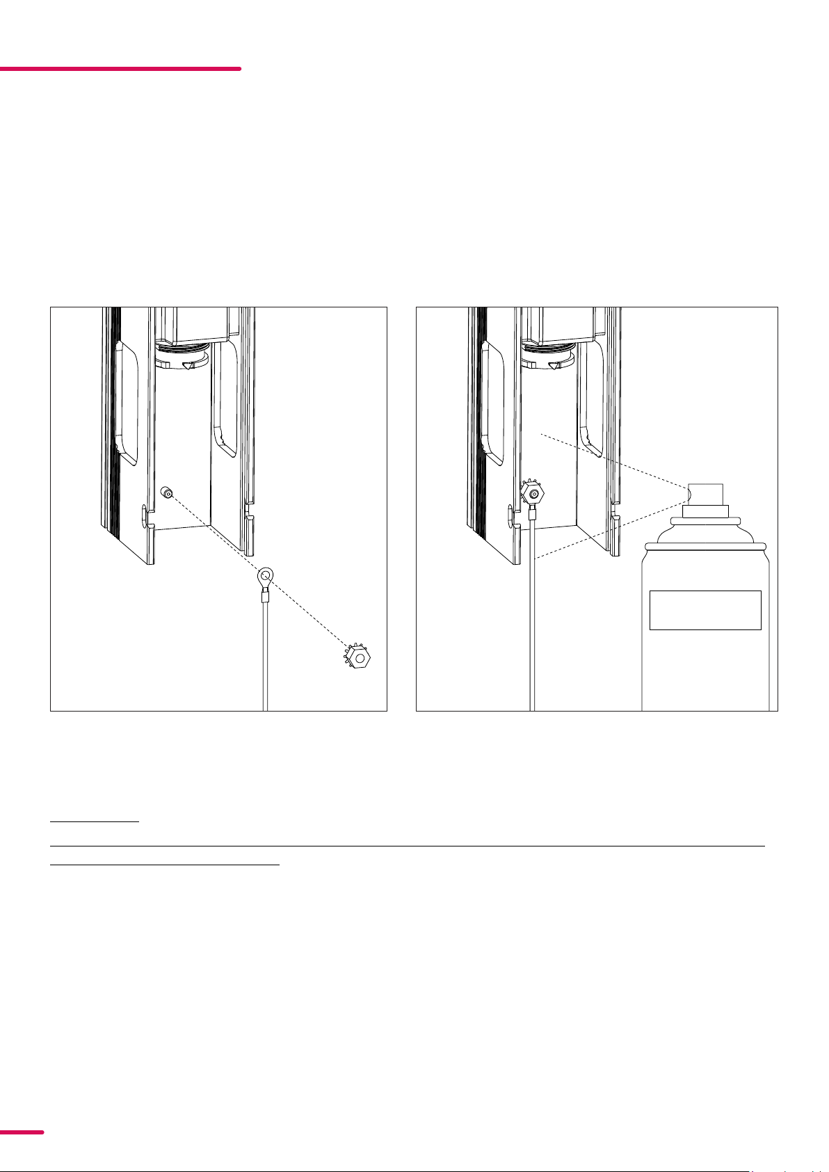
GROUNDING OF FIXTURES
When installing VPLs on the exterior of high buildings it is always recommended to ground the individual fixtures to
the building to minimize the risk of failure due to lightning strikes. Make sure to check the local building code for
possible directives or laws regarding lightning prevention.
INSTALLING GROUND WIRE
The GND/Earth Cable kit (P/N: 83062050) contains one ground wire (Green and yellow wire with a ring terminal, 1
meter) and one M3 nut with a star washer, which fits on the bolt near the female VP connector on the VPL. Remem-
ber to apply cavity wax after mounting the ground wire to prevent corrosion (see figure 9 and 10).
Cavity wax
Figure 9: Attach cable and nut Figure 10: Apply Cavity wax
CAUTION!
ALWAYS WEAR APPROPRIATE PERSONAL PROTECTION ACCORDING TO THE CAVITY WAX
PRODUCERS INSTRUCTIONS.
12 Product Version 1.0 | Revision D | Released 2023-01-10
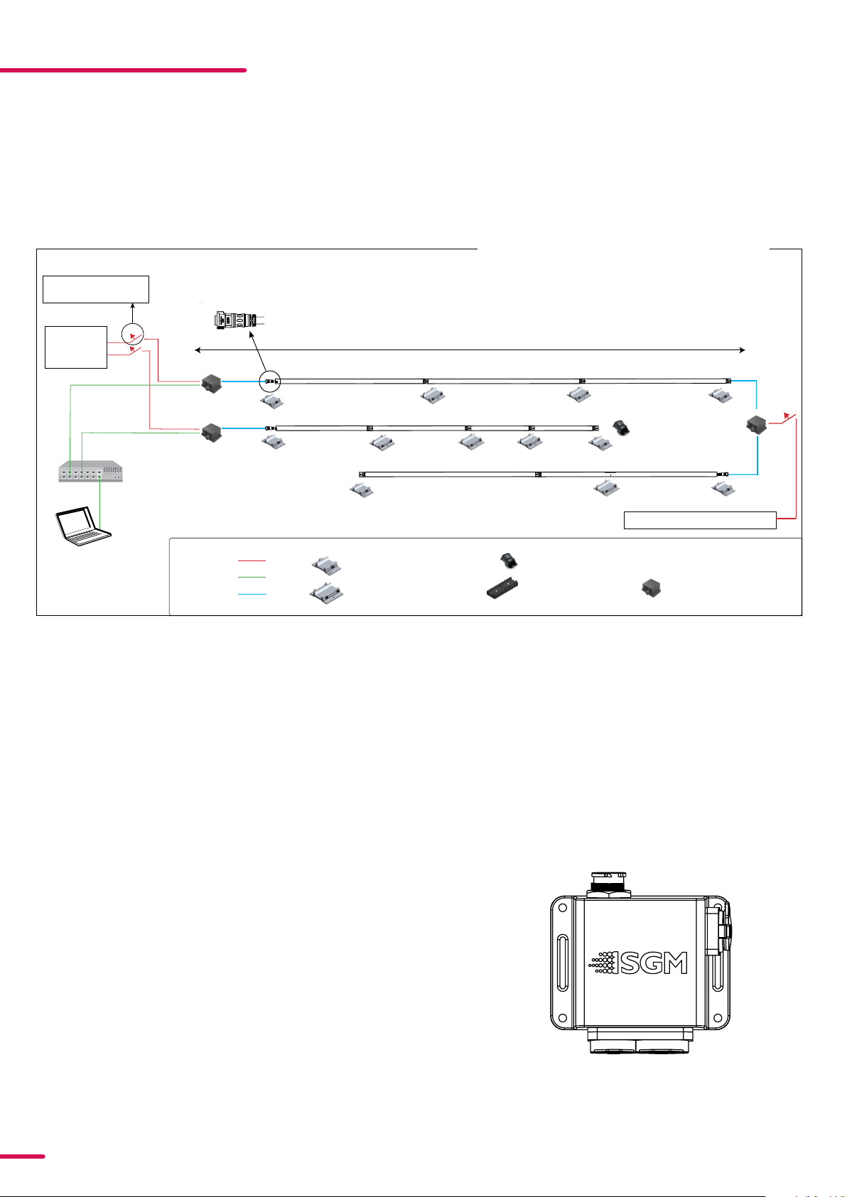
CONNECTING THE VPL SERIES
PERMANENTLY CONNECTING POWER & DATA
The VPL Series can operate on any 200–240 V, 50/60 Hz AC mains power supply. Power is connects to the fixture via
a Power+Data joiner or inserter (not included) (see figure 11 for connection diagram).
Figure 11: VPL Connection diagram
PLEASE NOTE! FOR SPECIAL INSTALLATIONS WITH MORE VPL STRINGS IN COMBINATION WITH MORE CABLE
LENGTHS IN BETWEEN, PLEASE CONTACT YOUR DISTRIBUTOR OR SGM SUPPORT.
Mains power
200-240 V
50/60 Hz
Artnet/sACN
K
l
i
n
g
-
N
e
t
Ar
tnet
s
A
C
N
10 Amp Type B Circuit
breaker, 3rd party
VPL - 1220-20
VPL - 610-20 VPL - 305-20
Main Power 200-240 V 50 / 60 Hz
Max 5 m.
Multicore 8 PIN Connector 1 x Shield, 3 x Power, 4 x Signal
Max. 85m/278.8 ft (230V) or 60m/196.8ft (200V) from the breaker to the last unit
VPL Touring bracket
(For third party clamps)
VP End cap
VPL Dual installation bracket
VPL Single installation bracket
Power
Data
VP cable VP Power + Data Joiner
VPL Power
Inserter
Installation Connection and Mounting
VPL POWER & DATA JOINER
The VP Power + Data Joiner (see figure 12) is designed to join
power and data for a daisy chain of VP fixtures. One VP Power +
Data Joiner can send power and data up to 65 VPL 1220-20 units
at 240 volts and 45 units at 208 volts. It is recommended to
install a 10amp type B circuit breaker for each string of cabled
VPL fixtures.
Power
Power + Data
RJ-45
Figure 12: VPL Power + Data Connector

13 Product Version 1.0 | Revision A | Released 2023-01-10
Connect the fixture to AC power using a SGM Power + Data joiner (not included) or similar. To ensure the correct
ingress protection (IP-rating), always use the SGM VP cables, and waterproof RJ-45 kit (see figure 13)
Order number: (83062057).
The power cable must be grounded/earthed, and the AC power supply must incorporate a 10 amps type B circuit
breaker for fault protection.
For a temporary outdoor installation, the power cable must be fitted with a grounded connector intended for
exterior use.
For permanent installations, have a qualified electrician to wire the power cable directly to a suitable branch circuit.
All cabling and distribution ingress protection (IP) rating must be suitable for the location.
CONNECT TO AC POWER
WARNING!ALWAYS ENSURE THAT THE INSTALLATION DOESN’T EXCEED THE
MAXIMUM CAPACITY IN A DAISY-CHAIN.
Figure 13: Waterproofing an RJ-45
PLEASE NOTE! THE BUILTIN PROTECTIVE CAPS MUST BE SECURELY
MOUNTED ON ANY UNUSED POWER OR DATA CONNECTORS, AND
VP END CAPS SEE FIGURE 14 INSTALLED IN THE UNUSED FIXTURE'S
VP CONNECTORS THE FIXTURES, IN ORDER TO MAINTAIN THE
IPRATING.
CAUTION!
DO NOT CONNECT THE FIXTURE TO AN ELECTRICAL
DIMMER SYSTEM, AS DOING SO MAY CAUSE DAMAGE
AND VOID WARRANTY.
Figure 14: VP End Cap

14 Product Version 1.0 | Revision A | Released 2023-01-10
CABLE LENGTHS
SGM offers 3 lengths of extension cable; 1m, 2.5m and 5m. However, it is possible to purchase a Custom Extension
Cable Kit in either 1m or 10m (1m: P/N 83062054, 10m P/N 83062055), and the Crimping tool for VP connectors(P/N
83062301), to make cables of any length. The cables have one moulded connector while the other end is ready to be
cut in the desired length. Note that only one cable can be made from each Custom Extension Cable Kit, and that
the Crimping tool is necessary to install the adapters.
1. Cut the cable in the desired length
2. Disasemble the X-lok connector and lead the cable through the seal cap (see figure 15).
3. Strip the cable with suitable tools. The exposed copper wire should be 9-11mm (see figure 16).
4.Mount the crimping pins and use the VP Crimping tool (see figure 17) to securely fasten them. The power
cables use AWG 16 pins while the data pins use AWG 26.
5. Insert the crimped pin in the clamp ring according to the illustration in figure 18.
Seal CapVP Cable Clamping ring Connector
AWG 16
AWG 26
Figure 15: X-lok parts
Figure 16: VP Cable
ALTW
O
P
E
N
16 AWG
26 AWG
Release switch
Figure 17: VP Crimping tool
PLEASE NOTE! THE VP CRIMPING TOOL CAN ONLY OPEN AFTER COMPLETELY PRESSING THE TOOL, OR
SWITCHING THE RELEASE SWITCH. DO NOT FORCE IT!

15 Product Version 1.0 | Revision A | Released 2023-01-10
VP CONNECTOR
The VPL Series has a female multi-core 8 pin cable located in the first end of the VPL, and a male multicore 8 pin
connector in the last end of the VPL. The 8 pins are divided by 1xShield, 3xPower, 4xSignal (see figure 18).
Figure 18: VPL female connector
The fixture must be grounded/
earthed and be able to be isolated
from AC power. The AC power
supply must incorporate a fuse or
curcuit breaker for fault protection.
Color
Black
White
green/yellow
Conductor
live
neutral
ground (earth)
Symbol
or
L
N
Wire
The power cable color coding:
• Connect the black wire to live
• Connect the white wire to neutral
• Connect the green/yellow wire to ground
(earth)
The recommended way to install VPLs and
brackets is to install one at the time. Although it is
possible to mount the brackets first, the inherent
expansion and contraction of the aluminium
profiles, from which the VPLs are made, can cause
complications where temperatures may vary.
PLEASE NOTE! WHENEVER SINGLE AND DUAL
BRACKETS ARE USED AT THE SAME TIME RE
MEMBER TO TAKE THE SIZE DIFFERENCE INTO
CONSIDERATION
10mm
4mm
14mm
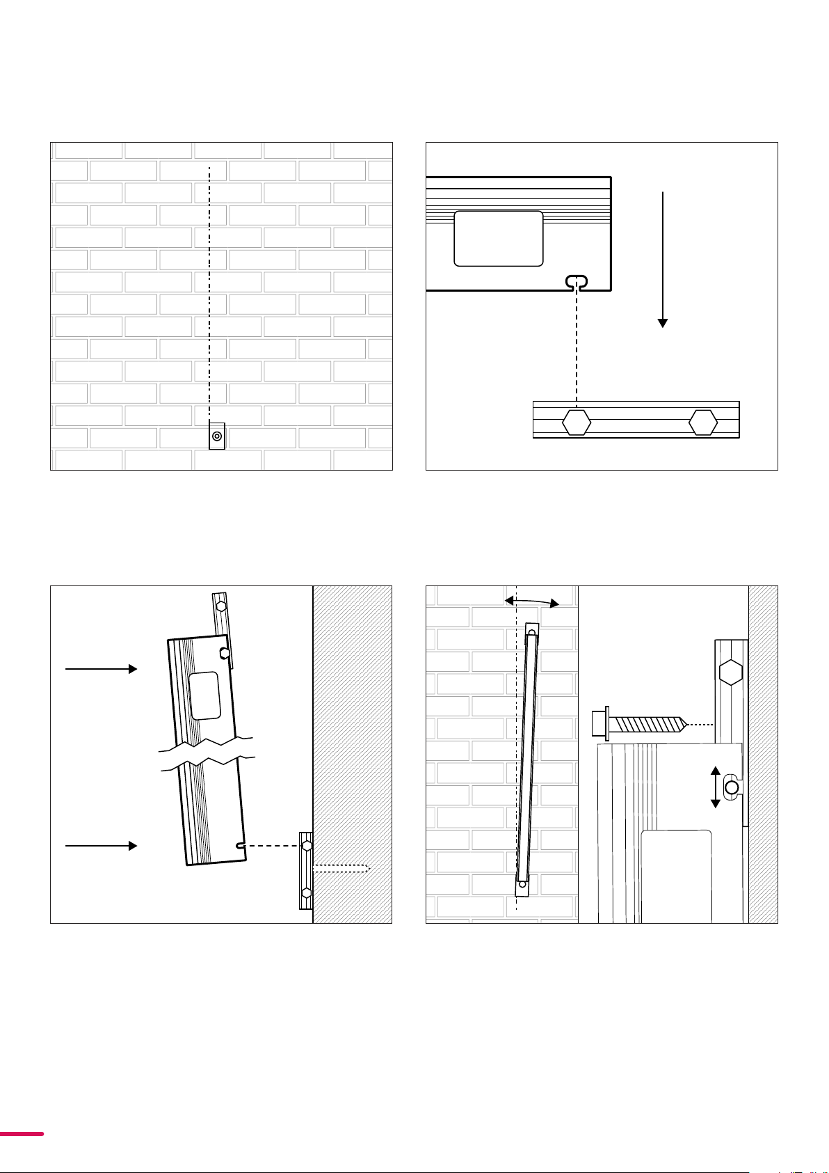
INSTALLING THE FIXTURES
MOUNTING
Figure 19: Power cable color code
1 — Power - White
2 — Power - Yellow/Gr
een
3 — Power - Black
4 — Data - White
5 — Data - Green
6 — Data - Red
7 — Data - Blue
8 — Data - Shield
16 Product Version 1.0 | Revision A | Released 2023-01-10
Step 2
Attach a second bracket to the VPL at the end with the
oblong hole, by clicking it into place.
Step 3
Click the VPL into the installed bracket. Remember
to tighten the bolts.
Step 4
Align the VPL to the guides and adjust the bracket so
the bolts are centered in the oblong hole. This will
prevent thermal expansion difficulties.
Step 1
Draw the linear path guide-lines for the VPLs and
install the first bracket

17 Product Version 1.0 | Revision A | Released 2023-01-10
REPLACING A FIXTURE DEMOUNTING
1
Single
hole
2
Oblonge
hole
Step 1
Loosen the bolts while holding the profile and
begin to loosen the single hole side bracket.
Step 2
Remove the VPL by carefully twisting the profile
off the bracket. You can get a grip through the
hole near the connector.
1
2
Step 3
When the profile is free, remove the VP cable
starting with the lower cable, and remove the
fixture.

18 Product Version 1.0 | Revision A | Released 2023-01-10
REPLACING
1
21
2
Step 1
Insert the power/data cable and ensure that it is
connected properly with a click sound on insertion.
Confirm the alignment of the arrows .
Step 2
Click the VPL into the brackets with the oblong hole first
and the single one after. Tighten the bolts after installa-
tion.
The VPL is intended to be set up for use prior to programming using the SGM Network Admin software available for
PC. Using the Admin software, the VPL system is designed for easy installation and patching. For detailed instruc-
tions and guidance on setup and configuration, please refer to the SGM Network Admin. The software and manual
for the SGM Network Admin is available at www.sgmlight.com .
It is recommended that any network design and installation be facilitated by personnel trained and experienced
with the programming and use of pixel control products. SGM recommends to always use dedicated professional
networks, instead of standard corporate networks.
VPL NETWORKING GUIDE

19 Product Version 1.0 | Revision A | Released 2023-01-10
NETWORK SETUP
The VPL fixtures can work properly in a wide array of network setups. Depending on the size of your network and
installation, there may be further considerations to effectively manage the data traffic of large scale RGB pixel style
control.
If possible, SGM advises keeping VPL networks separated from general building networks or using VLAN’s to avoid
excess network traffic. Networked data traffic for pixel control is not suitable for typical TCP/IP network settings and
often is not able to be managed effectively with general IT personnel.
VPLs address themselves automatically in the 2.x.x.x /8 range on start-up. This method has been designed to make
setup easier and to optimize the reliability of the system. It is possible to change the IP address if necessary.
The VPL product line receives and transmits information via sACN or Art-Net ethernet protocols. Both are Universal
Datagram Packet (UDP) type protocols. UDP protocol can be networked in the same topology as TCP, but there are
some important considerations for effectively routing and managing UDP in a large full-duplex network.
Art-Net, sACN, and Broadcasting Considerations
sACN and Art-Net are communication protocols developed to transport DMX512 data over an Ethernet network.
Both sACN and Art-Net can utilize Broadcast, Unicast, or Multicast, but there are some important differences in how
they can use these casting types.
Art-Net
By default an Art-Net product will factory start using a Class A IP address scheme in the 2.x.x.x range, since this
allows Art-Net products to communicate directly and without the need for a DHCP server to be connected to the
network. This is also the case of VPLs.
In large installations, especially ones utilizing ACN (Architecture for Control Networks), it is important to note that
Art-Net cannot offset DMX512 universes and cannot be put into different ACN ranges.
sACN
sACN (or ANSI E1.31 – 2016) is primarily intended to use multicast. Network switches have differing levels of support
for multicasting. To handle multicast data correctly, a switch needs to know which multicast subscribers are at-
tached to which of its physical ports. It obtains this information by monitoring IGMP packets. If the switch does not
see these packets, it will either treat the packets as unwanted and block them, or convert the packets to broadcast.
This is important because the maximum number of sACN DMX512 universes is 63,999. An unintended broadcast of
that much data can take down everything connected to the network, large or small.
The VPLs are by default in the 2.x.x.x range but that range can be changed. The network still needs to be configured
to the same range the VPLs are in.
IGMP
Multicast requires some additional network management on the part of the controller and receiver. VPL uses
Internet Group Management Protocol (IGMP) version 3 for this management. In a VPL network, controllers and
connected equipment must support IGMP v3 to manage the subscription of multicast addresses in network routers.
For more information on:
Art-Net, please see https://art-net.org.uk/
• sACN (ANSI E1.31 – 2016) or,
• RDM (ANSI E1.20 – 2010) or,
• DMX512 (ANSI E1.11 - 2008 (R2018)) please see TSP (esta.org)

20 Product Version 1.0 | Revision A | Released 2023-01-10
UNIVERSAL DATAGRAM PACKET UDP
UDP is used for entertainment lighting data because it is fast. Speed and timing are critical in creating coordinated,
instant changes in a pixel array. Network infrastructure products such as switches are typically designed for TCP/IP
packet traffic with occasional UDP data. They also expect to see the majority of data as unicast. Lighting control
networks often contain mainly UDP and can contain a significant percentage of broadcast data.
In Full-Duplex networks, The TCP and UDP protocols are part of the IP layer. Both TCP and IP have their own flow
control techniques. However, the TCP and IP methods of flow control are oblivious of each other and having both
enabled on a network can lead to problems. For this reason, many ethernet switch manufacturers ship their prod-
ucts with IP flow control disabled, assuming that TCP will handle its own flow control. That assumption is fair in an
office environment. However, entertainment networks tend to be primarily UDP which does not have any flow
control. SGM recommends to enable IP based flow control if possible.
NETWORK SIZE
SGM does not specify a preferred topology for a network. However, in large networks, the introduction of routers and
extra switches can introduce data delays on the signal path. It is recommended to incorporate a minimum of
devices between the lighting data controller and the VPL installation.
VPLs can make use of Rapid Spanning Tree if desired. However, the above applies if the signal path is lengthened or
routed in a significantly different way in the event of a path change. See later in this manual for details on how
Rapid Spanning Tree is handled.
FIXTURE PROPERTIES
FACTORY DEFAULT
From the admin tool the factory default settings can be re-initialized. This can be set for each available VPL or all
VPL´s - even when the VPL´s are located in another IP range.
Hall sensor input on the actual VPL can be activated with a magnet. On the trailing edge of an activation the state is
shifted one position.
State 1 - RED LED´s test
State 2 - GREEN LED´s test
State 3 - BLUE LED´s test
State 4 - WHITE LED´s test
State 5 - GREEN LED count sequence. Hall sensor activation for 10 seconds = VPL will re-initialize factory defaults
and restart.
State 1…
Alarm service
Monitoring of a VPL installation. If a VPL is not online a service technician is automatically notified.
This manual suits for next models
3
Table of contents
Other SGM Lighting Equipment manuals


Popular Lighting Equipment manuals by other brands

Visual Comfort & Co.
Visual Comfort & Co. Darlana Assembly instructions

PoolRite
PoolRite Surechlor 4000 owner's manual

5Star Systems
5Star Systems Spica 250M user manual

S.R.Smith
S.R.Smith VORTEX Assembly and installation instructions

Laserworld
Laserworld GREEN-4000 user manual

Briloner
Briloner MAL 2069-090P Mounting instructions


thomann
thomann STAIRVILLE Led Par 64 CX-7 CW/WW/A user manual

Artistic Licence
Artistic Licence lightJuice CV4 user guide

BEGLEC
BEGLEC JBSystems Light LED Par 56 Operation manual

Aputure
Aputure Light Storm LS 600d product manual

BRUSTOR
BRUSTOR B25 Series installation instructions

Pixlip
Pixlip FP50 LIGHTBOX Assembly instruction