SGM P-5 Wash Light User manual

Wͳϱ
Wͳϱt,/d
WͳϱdhE>t,/d

2
P-5 Series dimensions
All dimensions in milimeters and inches.
Drawing not to scale.

3
P-5 WASH LIGHT
USER MANUAL REV. 4
© 2012 SGMTM
companies disclaim liability for any injury, damage, direct or indirect loss, consequential
or economic loss or any other loss occasioned by the use of, inability to use or reliance
on the information contained in this manual. The SGM logo, the SGM name and all other
English edition

4
Contents
Safety information.................................................................................................... 6
Overview.................................................................................................................. 8
Preparing for installation.......................................................................................... 9
.................................................................................................... 10
Connecting AC power............................................................................................ 12
........................................................................................... 13
Setting a static color manually............................................................................... 14
Using stand-alone operation..................................................................................
Connecting to a DMX control device ..................................................................... 16
................................................................ 17
Device personality settings.................................................................................... 20

Service................................................................................................................... 22
DMX protocols....................................................................................................... 23
Control menu......................................................................................................... 32
........................................................................................................ 38
6
Safety information
P-5 series luminaires are intended for professional use only. They are not suitable for household use.
Review the following safety precautions carefully before installing or operating the device.
Preventing electric shock
Do not open the device; there are no user-serviceable parts inside.
Ensure that power is cut off when wiring the device to the AC mains supply.
Ensure that the device is electrically connected to earth (ground).
Do not apply power if the device or mains cable is in any way damaged.
DANGER! Risk of electric shock. Do not open the device.
WARNING! Read the safety precautions in this section before
installing, powering or operating this product.
7
Install in a location that prevents accidental contact with the device.
Install only in a well-ventilated space.
Install at least 0.3 m (12 in.) away from objects to be illuminated.
Install only in accordance with applicable building codes.
Ensure a minimum clearance of 0.1 m (4 in.) around the cooling fans.
Do not look directly at the light source from close range.
Take precautions to prevent injury due to falls when working at height.
For permanent installation, ensure that the device is securely fastened to a load-bearing surface with suitable
corrosion-resistant hardware.
For temporary installation with clamps, ensure that the quarter-turn fasteners are turned fully and secure with a
suitable safety cable, one that is able to bear 10 times the weight of the device.
WARNING! Take measures to prevent personal injury.
8
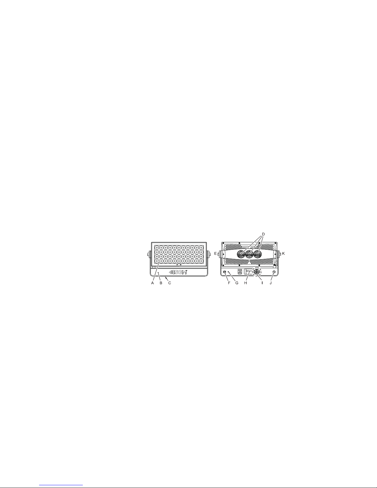
Overview
A
B
CSafety wire eyelet
DCooling fans
ETilt lock
FDMX in and out
G
H
IControl panel
JPower connection
KTilt lock

9
Preparing for installation
Unpack the device and inspect it to ensure that it has not been damaged in transport.
TM
G4 wireless antenna.
Is situated away from public thoroughfares and protected from contact with people.
Has adequate ventilation.
10
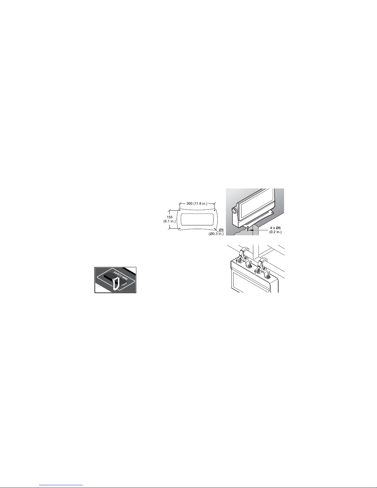
Installing the P-5
For permanent installation on the ground,
stand/base. Fasten securely through the
resulting holes with four 6 mm (1/4 in.)
corrosion-resistant mechanical fasteners
suitable for the location.
using the supplied brackets and suitable clamps.
Fasten a safety cable (not shown) between the support
structure and the attachment point on the device. The
safety cable must be able to bear at least 10 times the
weight of the device.
Dimensions in milimeters and inches

11
The device can be tilted from -10/+100 degrees. To adjust the tilt angle, loosen the two tilt
screws.
If installed horizontally with a downward beam-angle, water can potentially pool in the fan
wells. Under normal operation the moisture will evaporate.
If the device has been operating, always allow it cool for 15 minutes before handling.
"#$%&

12
Connecting AC power
power.
The device must be grounded/earthed and be able to be isolated from AC power. The AC power supply must
incorporate a fuse or circuit breaker for fault protection.
system, as this can damage it.
13
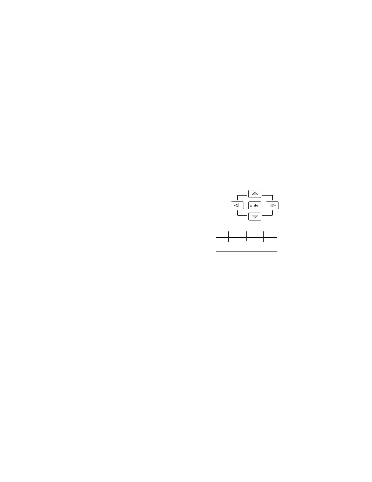
Navigate the menus and options using the arrow buttons and select items using the
and other information.
A- Operational mode (Quick color, stand-alone or DMX mode)
B- DMX address (if DMX mode is active)
C
D
carrier frequency).
6CH MODE ・DMX
8
ABCD

14
Setting a static color manually
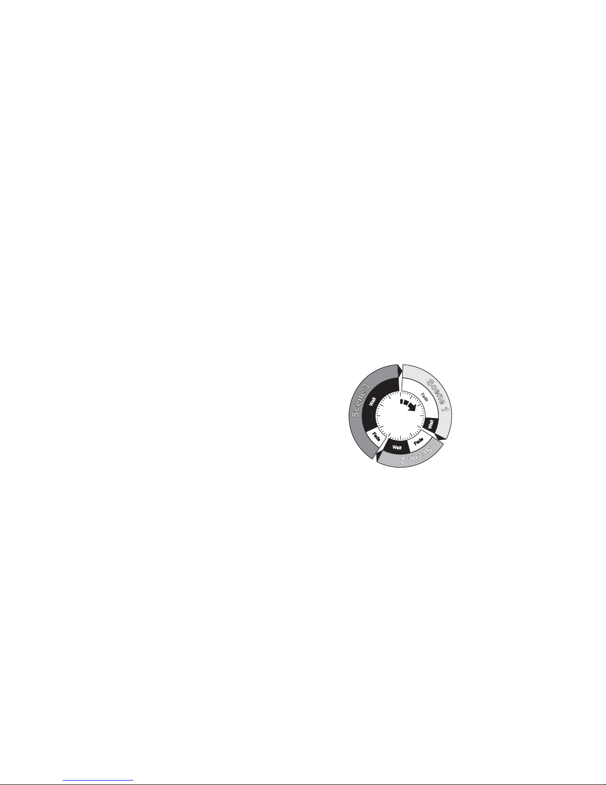
Using stand-alone operation
a description of the menus). The chosen program will run its length
A program can be run at any time by selecting it using the

16
Connecting to a DMX control device
The device is controllable using a DMX control device and it can be connected using either DMX cable or via the
TM G4 receiver system.
Enabling the W-DMX G4 wireless receiver
TM G4 wireless receiver is disabled by default. Ensure that there
is no DMX cable connected to the device. Attach the supplied wireless DMX
antenna to the connector on the back of the device.
TM G4 operates at a frequency of 2.4

17
About DMX
then be set to a DMX address of 14. If two or more DMX devices of the same type have the same DMX address,
controller.
Setting the DMX address
The DMX address can be seen at the top of the menu structure. To
change the address setting, press the up arrow to increase the address,
is displayed, press Enter to save the setting. For your convenience, the
that channel spacing is determined by the DMX mode.
SET DMX ADR NEXT FIX
13
10

18
Setting the DMX mode
P-5 DMX modes Function
3
4
6
8
9
10
P-5 TW DMX modes Function
2
4
6
pulse & open shutter effects.
8

19
P-5 W DMX modes Function
1 Dimmer.
2 Dimmer, shutter, strobe, pulse & open shutter effects.
2 (16-bit) Fine and coarse dimmer.

20
Device personality settings
Setting the dimming curve
dimming. For uniform response, set all devices to the same dimming curve. To set the desired dimming curve, use the
"#$
%"#$
it dims. Pressing any key will always turns on the display or restore it to normal brightness. To enable the display saver,
Other manuals for P-5 Wash Light
3
This manual suits for next models
2
Table of contents
Other SGM Lighting Equipment manuals


