manuals.online logo
Brands
  1. Home
  2. •
  3. Brands
  4. •
  5. Shadowspec
  6. •
  7. Patio Furniture
  8. •
  9. Shadowspec Serenity User manual

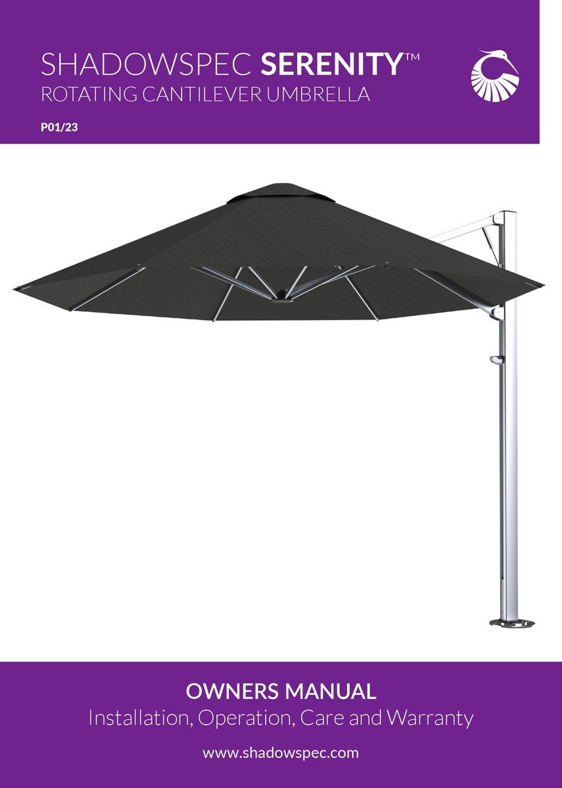
Shadowspec Serenity User manual

www.shadowspec.com
For Australia and New Zealand
HARDWIRE KIT INSTALLATION GUIDE
SHADOWSPEC SERENITY & UNITY™
P01/22
220v AC
Parts List - New Zealand & Australia Specicaon
Kit Code Part Code Image Part Name Notes Qty
UM - 510018
UM - 510019 12v AC/DC
Adapter
Capable of powering
up to 4 LED Lights. 1
UM - 510020 12v DC to 9v
Converter
One per LED light. Shadowspec
LED lights are strictly 9v DC 1
UM - 510021 5-way
connector
12vDC Feed wire to Voltage Con-
verter input wires 2
UM - 510022 Crimp
Connector
Voltage Converter output to Main
Spar Wire 2
UM - 510031 Connection
Cover
Connecting the feed wire to the
adapter. 2
UM - 510023 20m Feed
Cable
Garden Cable. One wire has ridge
to show polarity 1
UM - 510024
Cable Ties Cable management at the top of
the Mast 4
Base Kit - Shadowspec Serenity™ & Shadowspec Unity™
The Hard Wire Base Kit comes with the above components. Please check your kit to ensure that it is complete. If you have
a Shadowspec Serenity™ Umbrella, you will need one Base Kit per umbrella. If you have purchased a Shadowspec Unity™
you will need one Base Kit and then one addional Canopy Kit for each Canopy purchased.
Note: Aer your Hardwire Installaon, You can sll use your Shadowspec SS-1 Smart Controller, if you have one.
Please visit www.shadowspec.com/hardwire-kit for a video guide on how to install the hardwire kit.
Additional Canopy Kit
Kit Code Part Code Image Part Name Notes Qty
UM - 510025
UM - 510020 12v DC to 9v
Converter
Suitable for one LED light. Shad-
owspec LED lights are strictly 9V
DC
1
UM - 510022 Crimp
Connector
Voltage Converter output to Main
Spar wire 1
UM - 510026 Cable Ties Cable management at the top of
the mast 2
Addional Kits - Shadowspec Unity™
This product is subject to Equipotenal Bonding compliance in accordance with the
Australian/New Zealand Standards (AS/NZS 3000: 2018 Electrical Installaons)
otherwise known as the Wiring Rules and the USA code, NFPA 70, Naonal Electrical
Code (NEC) – 2020 edion - Arcle 680. If this product is installed within arms reach
(NZ/AU*) or 5’ (USA*) of a body of water including spa, swim spa or pool, then
Equipotenal Bonding MUST be performed by a licensed electrical person prior to the
product being used. This is a mandatory requirement. As the purchaser of this product,
you are responsible for ensuring compliance with this requirement at your own expense.
* Please verify the minimum distance required as spulated by your specific regional regulaons outside NZ/AU/USA
This product is subject to Equipotenal Bonding compliance in accordance with the Australian/
New Zealand Standards (AS/NZS 3000: 2018 Electrical Installaons) otherwise known as the
Wiring Rules and the USA code, NFPA 70, Naonal Electrical Code (NEC) – 2020 edion -
Arcle 680. If this product is installed within arms reach (NZ/AU*) or 5’ (USA*) of a body of
water including spa, swim spa or pool, then Equipotenal Bonding MUST be performed by a
licensed electrical person prior to the product being used. This is a mandatory requirement.
As the purchaser of this product, you are responsible for ensuring compliance with this
requirement at your own expense.
* Please verify the minimum distance required as spulated by your specic regional
regulaons outside NZ/AU/USA
Site Preperaon
General Notes and Safety
• The installaon of this permanent Hard Wire Kit is best done during the install of your umbrella.
• Roung the 20m Feed Wire safely and out of sight will require some preplanning.
• The wire must enter through the boom of the Umbrella Spigot and run up the inside of the Mast.
• For Concrete surfaces, ling or In-Ground Anchor installs, we recommend using a concealed conduit pipe
that enters through the surface plate and into the boom of the Spigot.
• Wooden decks with underneath access require the wire to be fed through a hole that aligns with the Spigot.
• The supplied Feed Wire cable can be laid underground in your garden.
• Take care not to run it together with 220V/110V AC cabling as this is not safe pracce.
• We do not recommend using the Hard Wire Kit where a portable base for the umbrella mount is used.
• The Installaon method is similar for both Shadowspec Unity™ and Shadowspec Serenity™ umbrellas.
Tip: Always Label cables where possible. This makes it much easier to do installs and nding faults later.
• We recommend consulng a cered electrician prior to installaon.
• Unplug the 12v AC/DC Adapter from the wall socket during install process or when not in use.
• Never install the 12v AC/DC Adapter in or near your UmbrellaMaintain at least a 2M distance.
• Only use the supplied 20m 12v DC Feed Cable into the umbrella.
• Ensure that the 12v AC/DC Adapter is plugged into AC power socket that has been installed by a cered
electrician and is protected from the outside elements.
• Do not cut or extend the AC Power Lead on the 12v AC/DC Adapter.
• Do not submerge the 12v AC/DC Adapter or any connecon point into water.
• Please take care to wire your umbrella light using the correct DC polarity: Do not mix the + and – wires as
this will damage your umbrella LED light.
• Ensure all wire connecons are secure and sealed with the supplied gel lled connectors.
• Do not connect any other 12V devices to the supplied 12v DC adapter as this will void your warranty.
Wiring Diagram
(1-4 Lights)
Connecon Point Informaon
Components for each Connecon Point
Note: 12v DC to 9v Converter is shared between Connecon Point 1
& Connecon Point 2
12v AC/DC Adatptor
Connecon Point 1
Connecon Point 1 Connecon Point 2 Connecon Point 3
Connecon Point 4
Low Voltage Feed Cable
Connecon Point 2 / 3
Surface Plate Wire Installaon
Tip: Shadowspec Serenity and Unity Spigots have the same wire path
If you are retrong the Hardwire Kit - Remove your
Umbrella from the Spigot.
Feed the Feed Cable through the Wire Feed Hole on
the Surface Plate and Spigot
Run the Feed Cable through the Spigot and into and
through the Mast.
Remove the Spirit Bubble from the top of your Spigot
In-Ground Anchor Wire Installaon
If you are retrong the Hardwire Kit - Remove your
Umbrella from the Spigot.
Feed the Feed Cable through the Wire Feed Hole on
the Surface Plate and Spigot
Install a conduate when you set the In-Ground Anchor
to make feeding the cable easier.
Remove the Spirit Bubble from the top of your Spigot
Spigot
In-Ground Anchor
Conduit with
Feed Cable
• The 220V AC/DC Adaptor Input Plug should only be used with a xed wall socket that was installed by a
cered electrician.
• Please use a wall socket that is mounted in a dry and protected area or a socket that has a rain proof lid.
• Please wall mount the adaptor o the ground, ensuring that it remains dry.
• The Adaptor has an IP67 rang which makes it rain proof but not suitable for submersion into water.
• Keep in mind that the light will need to be controlled from the wall socket so access to a switch is important.
• Minimum install distance of 2 Meters and a maximum distance of 40 Meters from your umbrella.
• Please secure and conceal all wiring to ensure a reliable connecon for years to come.
• All in-ground or exposed extension connecons should be done using a waterproof enclosure.
Important Safety Note: Do not plug the adapter into the 220V AC mains socket unl all the wiring is completed
as this could cause a short circuit as you wire the umbrella.
WARNING: Never cut or extend the 220v Mains Input Cable. Using a third-party adaptor or any other 12v DC
source will void the warranty on all the umbrella LED light components.
Important
Ridged Wire is ALWAYS Posive
Connecon Point 1: 12v AC/DC Adapter
Red is always the posive wire.
Connecon Point 1: 12v AC/DC Adapter
1. Strip the Feed Cable back about 15mm to expose
the bare wires.
2. Twist ghtly together with the 12v DC output
wires from the included adaptor - please ensure to
get the polarity correct.
3. Tightly push the Gel Filled caps over the connecon - ensure no bare wires are exposed.
Secure the wires so there is no chance of the connecon coming apart when the wires are pulled.
Connecon Point 2: 12V DC Feed cable to 9V DC Converter
r
12v - 9v
converter
12v - 9v
converter
12v - 9v
converter
12v - 9v
converter
WARNING: Always use the 12v DC to 9v DC converters to connect to the Main Spar LED wire. DO NOT
connect the 12V DC directly to the LED wire without using the supplied voltage converter.
Connecon Point 2: 12V DC Feed cable to 9V DC Converter
1. Remove the Top Cap from the Mast.
2. Feed the 12v Feed Cable from the Spigot (See Fig 1.) through
to the top of the Mast.
3. Secure the Feed Cable with supplied Cable Ties and place Mast
back on the Spigot.
4. Pull the Feed Cable taught and trim so you have 300mm of
Feed Cable protruding from the top of the Mast.
All connecons will be done outside the mast before being
returned to the top of the Mast.
Remove Mast
End Cap
12v Feed Cable
Li tabs
5. Strip the Feed Cable back about 10mm to expose the bare wires.
6. Roll each wire p together. Li the 5-Way Connector tabs and insert the Feed Cable all the way into the
connector holes.
7. Strip the ends of the supplied 12v DC to 9v DC Converter back about 10mm to expose the bare wire.
8. Insert the Black and Red side of the Converter into the 5-Way Connector.
The Red Wire is posive and MUST be in the same 5-Way connector as the Ridged Feed Cable.
9. Repeat the process for each light you are connecng if you have more than one.
10. Double check each connector to ensure polaries and colours aren't mixed.
1. Locate the Main Spar LED Cable at the back of the Main Spar.
2. With care, pull the loose end out of the transport hole.
3. Connect the Red Wire from the 9v DC Output to the Red Wire of the LED Cable with Crimp Connector.
4. Connect the Yellow Wire from the 9v DC Output to the Black Wire of the LED Cable with Crimp Connector.
Ensure the cables are pushed all the way into the Crimp Connectors.
5. Using a pair of plyers - squeeze the coloured cap on the Crimp Connector down unl it is ush.
The Connector will splice through the individual wire sleeve so there is no need to strip the wires.
6. Repeat the process for each canopy installed.
Cable feed
for Unity
example
Connect the Cables with Crimp ConnectorsCable locaon in Main Spars
Ensure Polarity is Correct
Connecon Point 3: 9v DC Output to Main Spar LED Wire
Connecon Point 4: Main Spar LED Wire to LED Light
1. Plug the Main Spar LED Plug into the LED Light via the DC Plug Connector.
Ensure the connecon is ght as this is a water-proof connecon.
2. Push any addional slack back into the Main Spar.
3. Repeat for each Canopy installed.
4. Test all cable connecons by carefuly pulling on them to ensure they are secure.
5. Double check all polarity across the system.
Red wires must only be connected to red wire
6. Return the Connecon Point 3 system to the inside of the top of the Mast.
7. Double check that all connecons inside the Mast are secure with no risk of bare wires touching each other
inside the Mast.
Ensure the Main Spar LED Cable ts into the Groove before returning the Top Cap
8. Use the supplied Cable Ties to secure the system.
9. Replace the Top Cap on the Mast.
Important: Connecng any third-party power source to the LED light will void the warranty.
Cable feed
for Serenity
example
Fault Suggested Soluons
The lights are not turning on when tesng • Double check that there is power at the mains
• Double check the Main Spar cable is plugged into the
LED Light
• Inspect all the connecons starng at connecon
point 1 all the way to 4
• Double Check Polarity on all connecons
The lights are not turning on aer previously
working
• Double check there is power at the mains
• Inspect all the connecons starng at connecon
point 1 all the way to 4
• Check for corrosion on connecon points
Not all lights are working (Shadowspec Unity) • Inspect the relevant connecons, starng with the
connecons closest to the light.
Connued issues • Failing the above, remove the LED Lens cover on the
Shadowhub and inspec the internal connecon to the
LED PCBA
Troubleshoong & Install Tips
Warranty and Aer Sales Support
• The obligaon of Shadowspec under this warranty is limited to faulty manufacturing, defecve materials,
and faulty parts for a period of 12 months. If any parts are replaced under warranty, the warranty period
will not be extended. Shadowspec shall, at its sole discreon, determine whether repair or replacement is
appropriate.
• This warranty does not cover the following:
• Damage caused by an accident, negligence, storm, wind, accumulaon of water or snow, or caused by an act
of God, incorrect installaon.
• Damage caused by exposure to hazardous atmospheric situaons due to industry or a high slat level.
• Damage by a third party.
• Repair by a third party.
• This warranty does NOT cover lightning damage, or any damage caused by power surges from the mains
supply. The foregoing sets out the extent of this warranty.
• Shadowspec shall not otherwise be liable or responsible for any direct, indirect, incidental, or consequenal
damage, costs or losses of any kind arising out of or in connecon with your umbrella or components
or for any delay by Shadowspec or the component manufacturer in undertaking repairs or replacement
under this warranty. Except as expressly provided herein, all other warranes, representaons, condions,
undertakings, rights, dues, or liabilies, whether arising by implicaon of law or otherwise, are hereby
expressly excluded.
• If you need to enquire about a warranty claim, please either contact Shadowspec direct or the sales agent
you purchased your product from.
Heron Base
Whangarei, Northland
0800 144 155
www.shadowspec.co.nz
NEW ZEALAND
Australian Nest
Laverton North, Victoria
1800 144 155
www.shadowspec.com.au
AUSTRALIA
Contact our in-house shade and outdoor specialists
for more informaon and advice.
North American Nest
Atlanta, Georgia
844 888 5577
www.shadowspec.com
UNITED STATES

This manual suits for next models

3

Other Shadowspec Patio Furniture manuals

Shadowspec RETREAT User manual

Shadowspec

Shadowspec RETREAT User manual

Shadowspec UNITY Octagon Duo User manual

Shadowspec

Shadowspec UNITY Octagon Duo User manual

Shadowspec SU3 User manual

Shadowspec

Shadowspec SU3 User manual

Shadowspec SERENITY ROTATING CANTILEVER UMBRELLA User manual

Shadowspec

Shadowspec SERENITY ROTATING CANTILEVER UMBRELLA User manual

Shadowspec RETREAT User manual

Shadowspec

Shadowspec RETREAT User manual

Shadowspec Serenity Cantilever Umbrella User manual

Shadowspec

Shadowspec Serenity Cantilever Umbrella User manual

Shadowspec SU7 User manual

Shadowspec

Shadowspec SU7 User manual

Shadowspec SU4 User manual

Shadowspec

Shadowspec SU4 User manual

Shadowspec UMBRELLAS Maintenance manual

Shadowspec

Shadowspec UMBRELLAS Maintenance manual

Shadowspec UNITY Square Uno User manual

Shadowspec

Shadowspec UNITY Square Uno User manual

Shadowspec SU4 User manual

Shadowspec

Shadowspec SU4 User manual

Popular Patio Furniture manuals by other brands

Costway HW67677 user manual

Costway

Costway HW67677 user manual

Proshade 1031593 Assembly instructions

Proshade

Proshade 1031593 Assembly instructions

Coolaroo JUMBO Care & maintenance

Coolaroo

Coolaroo JUMBO Care & maintenance

HAMPTON BAY ANDREWS UCS00301G Use and care guide

HAMPTON BAY

HAMPTON BAY ANDREWS UCS00301G Use and care guide

HOMEDEPOT L-DNC276PAL Assembly instructions

HOMEDEPOT

HOMEDEPOT L-DNC276PAL Assembly instructions

Homebase 585789 instruction manual

Homebase

Homebase 585789 instruction manual

HOMEDEPOT WG08G User and care guide

HOMEDEPOT

HOMEDEPOT WG08G User and care guide

HAMPTON BAY 074-CL-2PK-Y Use and care guide

HAMPTON BAY

HAMPTON BAY 074-CL-2PK-Y Use and care guide

HAMPTON BAY YJAF-052-C Use and care guide

HAMPTON BAY

HAMPTON BAY YJAF-052-C Use and care guide

Blue Wave Island Umbrella Cabo II Assembly instructions

Blue Wave

Blue Wave Island Umbrella Cabo II Assembly instructions

Factoryfurniture NORTH Operation & maintenance manual

Factoryfurniture

Factoryfurniture NORTH Operation & maintenance manual

Members Mark YJAUC-165A Assembly instructions & user manual

Members Mark

Members Mark YJAUC-165A Assembly instructions & user manual

HAMPTON BAY 1003 473 640 Use and care guide

HAMPTON BAY

HAMPTON BAY 1003 473 640 Use and care guide

Tuuci MAX Single Cantilever Assembly & operating instructions

Tuuci

Tuuci MAX Single Cantilever Assembly & operating instructions

furniture123 FTR085 Assembly instructions

furniture123

furniture123 FTR085 Assembly instructions

Uberhaus 77735191 user manual

Uberhaus

Uberhaus 77735191 user manual

EAST OAK EUBB001 owner's manual

EAST OAK

EAST OAK EUBB001 owner's manual

room & retreat UBS-879140 Assembly & care instructions

room & retreat

room & retreat UBS-879140 Assembly & care instructions

manuals.online logo
manuals.online logoBrands
  • About & Mission
  • Contact us
  • Privacy Policy
  • Terms and Conditions

Copyright 2025 Manuals.Online. All Rights Reserved.