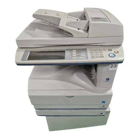
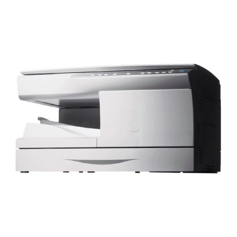
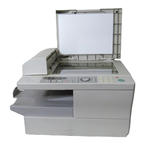
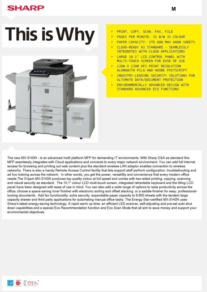
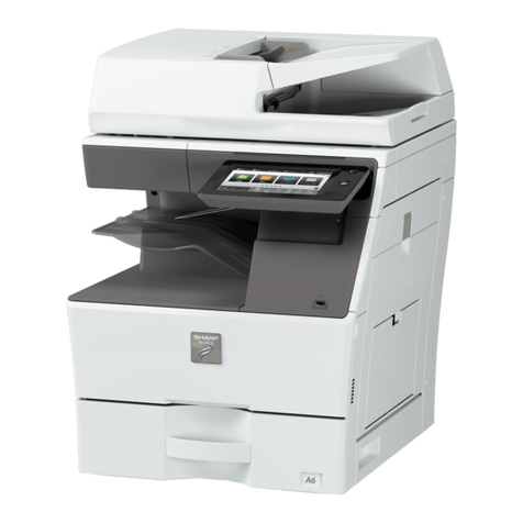
Sharp DM-2000 User manual

CODE: 00ZDM2010/A1E
NETWORK LASER
SYSTEM
DM-2005
MODEL DM-2010
[ 1 ] INTRODUCTION . . . . . . . . . . . . . . . . . . . . . . . 1 - 1
[ 2 ] DIFFERENCE FROM THE DM-2000 . . . . . . . . . . . . 1 - 1
[ 3 ] SPECIFICATIONS . . . . . . . . . . . . . . . . . . . . . . 1 - 1
[ 4 ] CONSUMABLE PARTS . . . . . . . . . . . . . . . . . . . 1 - 3
[ 5 ] INTERNAL STRUCTURES . . . . . . . . . . . . . . . . . 5 - 1
[ 6 ] UNPACKING AND INSTALLATION . . . . . . . . . . . . . 6 - 1
[ 7 ] ADJUSTMENTS . . . . . . . . . . . . . . . . . . . . . . . 6 - 1
[ 8 ] SIMULATIONS . . . . . . . . . . . . . . . . . . . . . . . . 6 - 1
[ 9 ] FAX SOFT SWITCH . . . . . . . . . . . . . . . . . . . . . 6 - 2
[10] FLASH ROM VERSION UP PROCEDURE . . . . . . . . . 6 - 2
[11] TROUBLE CODE LIST . . . . . . . . . . . . . . . . . . . 6 - 2
[12] USER PROGRAM . . . . . . . . . . . . . . . . . . . . . . 6 - 2
[13] DISASSEMBLY AND ASSEMBLY . . . . . . . . . . . . . . 6 - 2
[14] ELECTRICAL SECTION . . . . . . . . . . . . . . . . . . . 6 - 2
CONTENTS
Parts marked with “ ” are important for maintaining the safety of the set. Be sure to replace these parts with specified
ones for maintaining the safety and performance of the set.
SHARP CORPORATION
This document has been published to be used
for after sales service only.
The contents are subject to change without notice.
DM-2010

[1] INTRODUCTION
This model is an upgrade model of the DM-2000 network laser.
This Service Manual, therefore, describes only the different points from the DM-2000 as well as the supplement items. For the items which are not
described in this Manual, please refer to the DM-2000 Service Manual and Parts Guide.
[2] DIFFERENCE FROM THE DM-2000
For details of the specifications, refer to the basic specifications described later.
DM-2000 DM-2005 DM-2010
Copy speed 20PPM 20PPM 20PPM
Standard paper feed tray 2 steps + MB 2 steps + MB 2 steps + MB
Option paper feed tray Attachable Attachable Attachable 1 step or only one of 2 steps
Shifter (Offset paper exit) Standard Standard Standard
Job separator Standard Standard Standard
Page Memory Standard (10MB) Standard (10MB) Standard (10MB)
Scan one Print multi Standard ∗1 Standard ∗1 Standard ∗1
Document detection (Platen) Standard Standard Standard
Electrical Sort Option Option Option
SPF/RSPF SPF option RSPF standard SPF standard
LCD Display Standard ∗2 Standard ∗2 Standard ∗2
Printer Function (PCL6) Standard Standard Standard
Printer Function (PS2) Standard Standard Standard
Network Interface PWB Standard ∗3 Standard ∗3 Standard ∗3
Fax Function Option Option Option
∗1: The paper exit style is group only, sort is not available.
∗2: The copy mode status is not displayed. The status of printer and FAX is displayed.
∗3: Attached when installing the machine.
[3] SPECIFICATIONS
1. Copy mode
A. Type
Type Desk-top
B. Copy speed
(1) Basic speed
1 scan multi copy 20 sheets/min
Condition: Copy speed in the normal copy.
(2) Continuous copy speed (Sheets/min)
Paper size Normal Enlargement
(200%)
Reduction
(50%)
Inch
system
11" ×17" 10 10 10
8.5" ×14" 12 12 12
8.5" ×13" 12 12 12
8.5" ×11" 20 20 20
8.5" ×11"R 15 15 15
8.5" ×5.5" 20 20 20
C. First copy time
(1) Basic speed
First copy time 7.2 sec (8.5" ×11"/1st cassette/with OC)
D. Document
Max. document size 11" ×17"
Document reference position Left side center
Detection (Platen) Available
Detection size
11" ×17", 8.5" ×14",
8.5" ×11", 8.5" ×11"R,
8.5" ×5.5"
(1) SPF/R-SPF
Standard/
Option
DM-2005 RSPF: Standard
DM-2010 SPF: Standard
Document load capacity 30 sheets (56 ∼90 g/m215 ∼23.9
lbs equivalent)
Document size
(Max. ∼Min.) 11" ×17" ∼8.5" ×5.5"
Document replacement
speed
16 sheets/min (8.5" ×11" normal
copy)
Document set/Paper
feed direction
Face up, Center reference, Paper
feed from the top
Document weight 56 ∼90 g/m2, 15 ∼23.9 lbs
Document size detection On the document feed tray
Document mixture Copy mode: Not Available
DM-2010
1 – 1

E. Paper feed
Copy size
Max.: A3, 11" ×17"
Min.: A6, 5.5" ×8.5" (For B6/A6 and 5.5" ×8.5",
Multi bypass tray only.)
Paper feed
system 2 cassette + Multi bypass tray
Paper feed
capacity
250 ×2 (Paper feed tray) + 100 (Multi bypass
tray)(56 ∼80 g/m2equivalent)
Remaining
quantity
detection
Cassette section Empty detection available,
size detection by key input
Multi bypass tray Only empty detection
available
(1) Paper feed section of the copier
Paper feed
size
11" ×17", 8.5" ×14", 8.5" ×13", 8.5" ×11",
8.5" ×11"R, 8.5" ×5.5" (8.5" ×5.5" is only for
tray 1)
Side front Front 2 step
Paper feed
capacity
250 sheets (56 ∼80 g/m215 ∼21 lbs
equivalent)
Detection
Paper empty detection available, size detection
(by key input)
Detection size: 11" ×17", 8.5" ×14",
8.5" ×11", 8.5" ×11"R, 8.5" ×5.5"
Weight 56 ∼80 g/m215 ∼21 lbs
Special paper Recycled paper
(2) Manual paper feed section
Paper feed size 11" ×17" ∼5.5" ×8.5"
Paper feed capacity 100 sheets
Detection Size detection not available, paper empty
detection available
Weight 56 ∼128 g/m215 ∼34 lbs
Special paper Recycled paper, OHP film, labels
Paper feed Single except for recycled paper
(3) Option paper feed unit
1-step paper feed unit 2-step paper feed unit
Model DM-DE1 DM-DE2
Paper feed
size
11" ×17", 8.5" ×14", 8.5" ×11",
8.5" ×11"R
Capacity
(56 ∼80
g/m2)
About 250 sheets
×1 step
About 250 sheets
×2 steps
Paper
weight 56 ∼80 g/m215 ∼21 lbs
Dehumidifier
heater None
Detection Paper empty detection, size detection
(by key input)
Paper size
setting User setting (by key input)
External
dimensions
(W ×D ×H)
590 ×571 ×88 mm 590 ×571 ×173.5 mm
Weight About 5 kg About 10 kg
Special
paper Recycled paper
F. Job speed
S-S (1st step) 80% (document replacement rate)
Condition: With SPF
G. Multi copy
Max. number of multi copy 99 sheets
H. Warmup time
Warmup time Approx. 35 sec
(Condition: Standard condition)
Pre-heat Available
I. Copy magnification ratio
Fixed magnification ratio 50, 64, 77, 95, 100, 121, 129, 141,
200%
Zooming 50 ∼200%
Independent
zooming/vertical Available (50 ∼200%)
Independent zooming
(horizontal) Available (50 ∼200%)
J. Print density
Density mode Auto/Manual/Photo
No. of manual
adjustment 5 steps (Manual/Photo)
Toner save mode Set by the user program
K. Void width
Void area Lead edge 1 ∼4 mm, rear edge 4 mm or less,
both side 4 mm or less
Image loss Max. 5/32" (4 mm) (leading and trailing edges)
Max. 5/32" (4 mm) (along other edges in total)
L. Auto duplex
Standard/Option DM-2005 Standard
DM-2010 Not installable
M. Paper exit/finishing
Paper exit
section capacity Face down 250 sheets
Job separator
Job separator, Standard provision
Upper: FAX/Printer, Lower: Copier
Upper: 100 sheets, Lower 150 sheets
Full detection Available (Job separator)
Finishing Electronic sort board: Option (DM-EB1)
Electronic sort
capacity 8.5" ×11" standard document 60 sheets
Offset function Available (by the shifter)
Staple function None
DM-2010
1 –2

(1) Electronic sort board (Option)
Electronic sort
Sorting 60 sheets of A4 (8.5" ×11")
standard documents
Grouping 60 sheets of A4 (8.5" ×11")
standard documents
Rotation copy
If there is paper of same size as the document,
the image is rotated to copy even though the
paper is set in the different direction from the
document direction.
2 in 1, 4 in 1
Copies of 2 pages or 4 pages are integrated
into one surface. Divided by solid lines,
(Selectable by the user program.)
Edge erase
Images surrounding the document are erased
when copying. (Adjustable in 0 ∼20 mm (5 mm
step)/0" ∼1" (1/4" step) by the user program.)
Center erase
The image at the center is erased when
copying. (Adjustable in 0 ∼20 mm (5 mm
step)/0" ∼1" (1/4" step) by the user program.)
Margin shift Binding margin is made at the left edge of the
set documents.
N. Additional functions
APS (APS not available by flowing in
during use of SPF)
AMS (AMS not available by flowing in
during use of SPF)
Duplex Available only in DM-2005
Document count
Sorter When the electronic sort board
installed.
Independent zooming Vertical/Horizontal: 50 ∼200%
1 set 2 copy Enlargement inhibited, inhibited
during the use of SPF
Binding margin Shift width 9 mm/1/4"
Edge erase Adjustable 0 ∼20 mm/0" ∼1"
Black-white reversion Whole surface only
2 in 1, 4 in 1
Rotation copy
Memory copy Only one page memory installed.
Pre-heat function Conditions set by the user program
Auto power shut off
function Conditions set by the user program
Auto tray switching
Message display (FAX/Printer extension)
User program
Total counter
: When an option is installed
: Available : Not available
O. Machine composition
(1) Option
Machine Model Power supply
250 sheets paper feed unit DM-DE1 Supplied by the copier.
500 sheets paper feed unit DM-DE2 Supplied by the copier.
Electronic sorting kit DM-EB1 Supplied by the copier.
Facsimile expansion kit DM-FX1 Supplied by the copier.
DM-2010: Standard
2 MB FAX memory AR-MM5
4 MB FAX memory AR-MM6
8 MB FAX memory AR-MM7
P. Other specifications
Photoconductor type OPC (Organic Photo Conductor)
Photoconductor drum dia. 30 mm
Copy lamp Xenon lamp
Developing system Dry 2-component magnetic brush
development
Charging system Saw teeth charging
Transfer system (+) DC corotoron
Separation system (–) DC corotoron
Fusing system Heat roller
Cleaning system Contact blade
Q. Package form
Body Body/Accessories (NIC board is separately
packed.)
R. External view
External dimensions
(W ×D ×H) 590 ×531 ×654 mm (without SPF)
Occupying area
(W ×D)
590 ×531 mm
(When the multi bypass tray is installed.)
Weight About 43 kg
S. Power source
Voltage AC120V ±15%
Frequency 50/60Hz common
T. Power consumption
Max. power consumption About 1.5 KWh
∗EnergyStar standard (The second level conformity)
Pre-heat About 60 Wh
Auto power shut off About 4.8 Wh
U. Digital performance
Resolution Reading 400 dpi
Writing 600 dpi
Gradation Reading 256 gradations
Writing Binary
2. Printer Mode
For this item, refer to the DM-2000 Service Manual.
3. Fax Mode (Only DM-2010)
For this item, refer to the DM-FX1 Service Manual.
[4] CONSUMABLE PARTS
For this item, refer to the DM-2000 Service Manual.
DM-2010
1 –3

[5] INTERNAL STRUCTURES
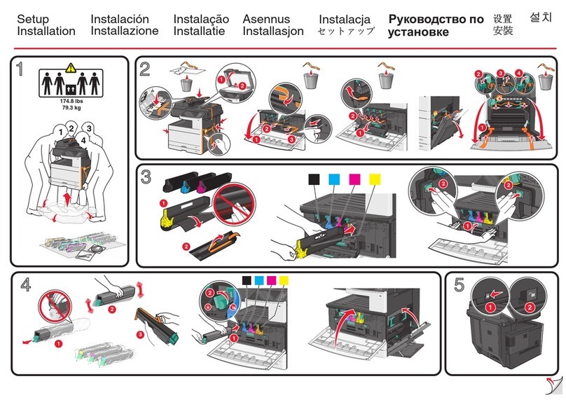
1. Motor, solenoid, clutch
No. Name Code Function, operation
1 Exhaust fan motor VFM Cools the inside of the machine.
2 Shifter motor SHTM Shifts the paper exit tray.
3 Toner motor TM Toner supply
4 Mirror motor MRM Drives the optical mirror base (scanner unit).
5 Duplex motor DPX Switchback operation and paper exit motor in duplex (only DM-2005)
6 Cooling fan motor CFM Cools the inside of the machine.
7 Main motor MM Drives the machine.
8 Paper feed solenoid CPFS1 Solenoid for paper feed from cassette
9 Resist roller solenoid RRS Resist roller rotation control solenoid
10 Manual paper feed clutch MPFC Drives the manual paper feed roller.
11 Manual paper feed solenoid MPFS Manual paper feed solenoid
12 Manual paper transport clutch MPTC Drives the manual paper transport roller.
13 Second tray transport clutch CPFC2 Drives the second tray transport roller.
14 Second tray transport solenoid FSOL2 Second tray transport solenoid
15 First tray transport solenoid FSOL1 First tray transport solenoid
16 Second tray paper feed solenoid PSOL2 Second tray transport solenoid
17 Paper feed clutch CPFC2 Drives the cassette paper feed roller.
18 First tray paper feed solenoid PSOL1 First tray transport solenoid
19 First tray paper feed clutch CPFC1 Drives the first tray transport roller.
20 PS clutch RRC Drives the resist roller
21 Job separator Motor LFTM Drives the Job-separator
21
1
24
3
9
8
10
7
6
11
12
5
13
14
15
16
17
18
19
20
DM-2010
5 – 1

2. Sensor, switch
No. Name Code Function, operation
1 Mirror home position sensor MHPS Detects the mirror (scanner unit) home position.
2 Document size sensor DSIN Paper size detection
3 Toner density sensor TCS Toner quantity detection
4 Paper exit sensor (paper exit side) POD1 Detects paper exit.
5 OC open/close sensor DOC COVER OC and SPF open close detection
6 Right door switch DSWR Side door open/close detection
7 Paper full sensor P FULL Paper exit tray section full detection <For JOB separator>
8 Lift sensor LFTHP Paper feed tray lift up detection <For JOB separator>
9 Lower limit sensor JTRAY Job separator tray lower limit detection
10 Paper exit sensor (DUP side) PDPX Paper transport detection
11 Shifter home position sensor SFTHP Shifter home position detection
12 Thermistor RTH Fusing section temperature detection
13 Thermostat Fusing section abnormally high temperature detection
14 1st tray detection switch CSD1 1st tray detection
15 Paper in PIN Paper transport detection
16 2nd tray detection switch CSD2 2nd tray detection
17 Manual sensor MPED Manual transport detection
18 Second cassette door open/close
sensor DRS2 Second cassette door open/close detection
19 Second cassette paper entry sensor PPD2 Paper transport detection
20 First tray paper empty sensor CSS1 First tray paper empty detection
21 Second tray paper empty sensor CSS2 Second tray paper empty detection
22 Drum reset switch DRST New drum detection switch
23 Power switch MAIN SW Turns ON/OFF the main power source.
123
6
5
4
7
8
9
10
11
13
14
12
15
16
17
18
19
20
22
23
21
DM-2010
5 –2

3. PWB unit
No. Name Function, operation
1 Copy lamp Inverter PWB Copy lamp control
2 FAX main PWB Fax communication control (only in DM-2010) (with DM-FX1 installed)
3 TEL/LIU PWB Line control (Fax communication) (only in DM-2010) (with DM-FX1 installed)
4 Printer control PWB Printer control
5 Network Board Network system interface
6 CCD sensor PWB Image scanning
7 Mother PWB
8 Main PWB (MCU) Machine control/Image process
Connecting the MCU and Printer/FAX PWB
9 Paper exit interface PWB Paper exit, finishing control
10 Tray interface PWB Paper tray control
11 High voltage PWB High voltage control
12 Operation main PWB Operation panel input/Display, operation panel section control
13 Power PWB AC power input/DC power control
14 LCD PWB Printer and FAX status display
15 Fax operation PWB Operation for FAX (only DM-2010) (with DM-FX1 installed)
124
39
8
10
7
6
11
12
5
13
14
15
DM-2010
5 – 3

4. Cross sectional view
No. Name Function/Operation
1 Copy lamp Image radiation lamp
2 Copy lamp unit Operates in synchronization with No. 2/3 mirror unit to radiate documents sequentially.
3 LSU unit Converts image signals into laser beams to write on the drum.
4 Lens unit Reads images with the lens and the CCD.
5 MC holder unit Supplies negative charges evenly on the drum.
6 Paper exit roller Used to discharge paper.
7 Transport roller Used to transport paper.
8 Upper heat roller Fuses toner on paper (with the teflon roller).
9 Lower heat roller Fuses toner on paper (with the silicon rubber roller).
10 Waste toner transport roller Transports waste toner to the waste toner box.
11 Drum unit Forms images.
12 Transfer charger unit Transfer images (on the drum) onto paper.
13 Duplex transport roller Transports paper for duplex (only DM-2005).
14 Resist roller Takes synchronization between the paper lead edge and the image lead edge.
15 Manual paper feed tray Manual paper feed tray
16 Manual paper feed roller Picks up paper in manual paper feed.
17 No. 2/3 mirror unit Reflects the images from the copy lamp unit to the lens unit.
18 Manual transport roller Transports paper from the manual paper feed port.
19 2nd tray paper transport roller Transports paper from the 2nd tray.
20 2nd tray paper feed roller (semi-
circular roller) Picks up paper from the 2nd tray.
21 1st tray paper feed roller (semi-circular
roller) Picks up paper from the 1st tray.
22 MG roller Puts toner on the OPC drum.
12 3 4 5
6
7
8
9
10
11
12
15
14
16
17
13
1819202122
DM-2010
5 –4

5. SPF/RSPF section
No. Code Name Type Functuion/Operation
1 W0 Document set sensor Photo transmission Detects presence of documents.
2 COVER Open/close sensor Photo transmission Detects open/close of the paper feed unit.
3 W1 Document width sensor (A4R, LTR, A5) Photo transmission Detects the document width on the tray.
4 W2 Document width sensor (B4, B5) Photo transmission Detects the document width on the tray.
5 W3 Document width sensor (WLTR, A5R, A4, LT) Photo transmission Detects the document width on the tray.
6 PSOL Pickup solenoid ––
7 PAPER Paper entry sensor Photo transmission Detects presence of documents.
8 RSOL Pressure release solenoid ––
9 CLH Transport clutch ––
10 MOT SPF motor Stepping motor Drives document feed on the tray, transport,
and paper exit roller.
11 GSOL Gate solenoid ––
12 –Interface PWB ––
13 L1 Document length detection SW (Short) Photo transmission Detects the document length on the tray.
14 L2 Document length detection SW (Long) Photo transmission Detects the document length on the tray.
15 COVER OPEN Book sensor Photo transmission Detects the SPF float.
No. Part name Operation
1Document length
sensor (L2)
Detects the document length on
the tray.
2Document length
sensor (L1)
Detects the document length on
the tray.
3Document set
sensor (W0) Detects presence of documents.
4
Document width
sensor (W1, W2,
W3)
Detects the document width.
5 Pickup roller Picks up documents.
6 Paper feed roller Feeds and transports documents.
7Paper entry sensor
(PAPER) Detects transport of documents.
8 PS roller
Makes synchronization between
the document lead edge and the
image lead edge.
9 PS follower roller
Makes synchronization between
the document lead edge and the
image lead edge.
10 Transport roller Transports documents.
11 Transport follower
roller Transports documents.
12 Paper exit follower
roller Discharges documents.
13 Paper exit roller Discharges documents.
14 Reverse gate Opens/closes the document
reverse path.(RSPF only)
15 Paper exit gate Separate document exit to the
intermediate or the paper exit tray.
16 Intermediate tray
Discharges documents to the
intermediate tray during document
reverse.(RSPF only)
12
3
4
5
6
7
9
8
10
11
12
13
14
15
12 3,45678
910111213 141516
DM-2010
5 –5

[6] UNPACKING AND INSTALLATION
For this item, refer to the DM-2000 Service Manual and the DM-FX1
Service Manual.
[7] ADJUSTMENTS
For this item, refer to the DM-2000 Service Manual and the DM-FX1
Service Manual.
[8] SIMULATIONS
1. Entering the simulation mode
A. Copy mode
The following key operations allow to enter the simulation mode from
the copy mode.
Clear key →Interruption key →“0” key →Interruption key →Main
code →Start key →Sub code →Start key
B. FAX mode
The following key operations allow to enter the simulation mode from
the FAX mode.
Clear key →Interruption key →“0” key →Interruption key →Main
code →Start key →Sub code →Start key
Or perform the following key operations:
“9” key →“ ” key →“8” key →“#” key →“7” key
2. Cancelling the simulation mode
When the all clear key is pressed, the simulation mode is cancelled.
When the interruption key is pressed, the process is interrupted and the
screen returns to the sub code entering display.
* After canceling the simulation mode, be sure to turn OFF/ON the
power and check the operation.
3. List of simulations
A. Copy mode
Main
code
Sub
code Contents ∗
1 1 Mirror unit operation check
2 Optical system sensor operation check
2 1 SPF aging B
2 SPF sensor operation check B
3 SPF motor forward rotation operation check B
4 SPF motor reverse rotation operation check B
8 SPF paper feed solenoid operation check B
9 RSPF reverse solenoid operation check E
10 RSPF paper exit gate solenoid operation
check E
11 SPF PS release solenoid operation check B
3 2 Shifter job separator sensor operation check
3 Shifter operation check
4 Job separator operation check
11 Shifter home position check
5 1 Operation panel display check
2 Heater lamp lighting check, cooling fan
motor operation check
3 Copy lamp lighting check
6 1 Paper feed solenoid operation check
10 Main cassette semi-circular roller drive
Main
code
Sub
code Contents ∗
7 1 Aging with warmup time display
4 Warmup saving
6 Intermittent aging
8 Warmup time display
9 1 Duplex motor forward rotation operation
check E
2 Duplex motor reverse rotation operation
check E
4 Duplex motor rotation speed adjustment E
5 Duplex motor switchback time adjustment E
10 Toner motor operation check
14 Trouble (except for U2) cancel
16 U2 trouble cancel
20 1 Maintenance counter clear
21 1 Maintenance cycle setting
2 Mini maintenance cycle setting (Japan only) A
22 1 Maintenance counter display
2 Maintenance preset value display (Japan
only) E
3 JAM memory display
4 Total JAM counter display
5 Total counter display
6 Developing counter display
7 Developing preset counter value display
(Japan only) A
8 SPF counter display B
9 Paper feed counter display
12 Drum counter display
14 Copier ROM version display
22 15 Trouble memory display
16 Duplex print counter display E
17 Copy counter display
18 Printer counter display
19 Electronic sort counter display C
20 FAX print counter display D
21 Scanner counter display
24 1 JAM memory, JAM counter clear
2 Trouble memory clear
4 SPF counter clear B
5 Duplex counter clear E
6 Paper feed counter clear
7 Drum counter clear
8 Copy counter clear
9 Printer counter clear
10 Electronic sort counter clear C
11 FAX print counter clear D
13 Scanner counter clear
25 1 Main motor operation check
10 Polygon motor operation check
DM-2010
6 –1
Main
code
Sub
code Contents ∗
26 1 Option switch display
3 Auditor setting
5 Counter mode setting
6 Destination setting
10 Model name setting
22 Language setting
30 CE mark conformity control setting
32 Fan rotation duty change state setup
38 Cancel of stop at dram life over
42 Transfer timing adjustment
50 Black-white reversion function setup
51 Sort/Group copy temporary stop function
setup C
30 1 Machine sensor operation check
41 2 OC document sensor adjustment
3 Document sensor light reception level display
42 1 Developing counter clear
43 1 Fusing temperature setting
46 1 Copy density level adjustment
48 1 Main scanning (front/rear) direction
magnification ratio adjustment
(Copy/FAX/OC-SPF common)
2 OC mode sub scanning direction
magnification ratio adjustment in copying
5 SPF mode sub scanning direction
magnification ratio adjustment in copying B
6 OC mode sub scanning direction
magnification ratio adjustment in FAX D
7 SPF mode sub scanning direction
magnification ratio adjustment in FAX D
50 1 Copy image lead edge position adjustment
10 Paper off center adjustment
13 OC mode document off center adjustment
16 SPF mode document off center adjustment B
18 Duplex memory reverse print adjustment E
19 Duplex rear edge void adjustment E
51 2 Resist amount adjustment
63 1 Shading data check
64 1 Self printing mode
67 14 Printer Flash ROM Data Download
A: Not Used. B: SPF is required.
C: E-Sort PWB is required. D: FAX kit is required.
E: Duplex model
B. FAX mode
Main
code
Sub
code Content ∗
22 11 Fax related counter display
14 Fax ROM ver. Display
24 14 FAX related counter clear
46 12 FAX mode density adjustment (AUTO)
14 FAX mode density adjustment for each
resolution (Fine)
Main
code
Sub
code Content ∗
46 15 FAX mode density adjustment for each
resolution (Super Fine)
16 FAX mode density adjustment for each
resolution (Ultra Fine)
64 02 User switch front print
03 Soft switch setting table print
04 Dump list print
66 01 FAX related soft SW setup check/change
02 FAX related soft SW clear (Excluding
adjustment values)
03 FAX PWB memory check
04 Signal send mode
06 Confidential communication password print
07 Image memory contents output
08 Voice message clear A
10 Image memory clear
11 300bps signal send
13 Dial test
17 DTMF signal send mode
22 Handset sound volume adjustment A
30 TEL/LIU status change check
32 Received data check
34 Communication time measurement/check
37 Speaker sound volume adjustment
38 Time setup/check
∗A: Not used
4. Detail of simulations
For this item, refer to the DM-2000 Service Manual and the DM-FX1
Service Manual.
[9] FAX SOFT SWITCH
For this item, refer to the DM-FX1 Service Manual.
[10] FLASH ROM VERSION-UP PRO-
CEDURE
For this item, refer to the DM-2000 Service Manual and the DM-FX1
Service Manual.
[11] TROUBLE CODE LIST
For this item, refer to the DM-2000 Service Manual and the DM-FX1
Service Manual.
[12] USER PROGRAM
For this item, refer to the DM-2000 Service Manual and the DM-FX1
Service Manual.
[13] DISASMELBY AND ASSEMBLY
For this item, refer to the DM-2000 Service Manual and DM-SP1 ser-
vice manual.
[14] ELECTRIAL SECTION
For this item, refer to the DM-2000 Service Manual.
DM-2010
6 –2

(Danish) ADVARSEL !
Lithiumbatteri –Eksplosionsfare ved fejlagtig håndtering.
Udskiftning måkun ske med batteri
af samme fabrikat og type.
Levér det brugte batteri tilbage til leverandoren.
(English) Caution !
Danger of explosion if battery is incorrectly replaced.
Replace only with the same or equivalent type
recommended by the manufacturer.
Dispose of used batteries according to manufacturer’s instructions.
(Finnish) VAROITUS
Paristo voi räjähtää, jos se on virheellisesti asennettu.
Vaihda paristo ainoastaan laitevalmistajan suosittelemaan
tyyppiin. Hävitäkäytetty paristo valmistajan ohjeiden
mukaisesti.
(French) ATTENTION
Il y a danger d’explosion s’il y a remplacement incorrect
de la batterie. Remplacer uniquement avec une batterie du
même type ou d’un type équivalent recommandépar
le constructeur.
Mettre au rebut les batteries usagées conformément aux
instructions du fabricant.
(Swedish) VARNING
Explosionsfara vid felaktigt batteribyte.
Använd samma batterityp eller en ekvivalent
typ som rekommenderas av apparattillverkaren.
Kassera använt batteri enligt fabrikantens
instruktion.
(German) Achtung
Explosionsgefahr bei Verwendung inkorrekter Batterien.
Als Ersatzbatterien dürfen nur Batterien vom gleichen Typ oder
vom Hersteller empfohlene Batterien verwendet werden.
Entsorgung der gebrauchten Batterien nur nach den vom
Hersteller angegebenen Anweisungen.
CAUTION FOR BATTERY REPLACEMENT
DM-2010

COPYRIGHT © 1999 BY SHARP CORPORATION
All rights reserved.
Printed in Japan.
No part of this publication may be reproduced,
stored in a retrieval system, or transmitted,
in any form or by any means,
electronic, mechanical, photocopying, recording, or otherwise,
without prior written permission of the publisher.
SHARP CORPORATION
Digital Document Systems Group
Quality & Reliability Control Center
Yamatokoriyama, Nara 639-1186, Japan
1999 July Printed in Japan N
DM-2010
Other manuals for DM-2000
1
This manual suits for next models
2
Table of contents
Other Sharp All In One Printer manuals

Sharp
Sharp AR-M256 User manual

Sharp
Sharp AL-1552 User manual

Sharp
Sharp AR-122E N User manual

Sharp
Sharp AL-1651CS User manual

Sharp
Sharp MX-3115N User manual

Sharp
Sharp AR-M162 User manual

Sharp
Sharp AR-5316 X User manual

Sharp
Sharp AL-1045 Setup guide

Sharp
Sharp MX-M182 User manual

Sharp
Sharp AL-1661CS User manual

Sharp
Sharp MX-4501N User manual

Sharp
Sharp AR-C360P User manual

Sharp
Sharp MX-LCX3N User manual

Sharp
Sharp MX-C312 Guide

Sharp
Sharp MX-FR36U User manual

Sharp
Sharp MX-M1100 User manual

Sharp
Sharp MX-3610N User manual

Sharp
Sharp MX-C250E Guide

Sharp
Sharp MX-B455W Operating instructions

Sharp
Sharp AR 237M User manual