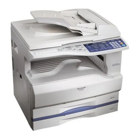
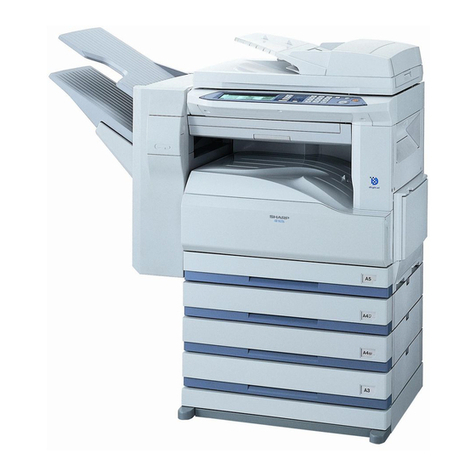
Sharp Z-810 User manual

SERVICE MANUAL
CODE: 00ZZ820S/M//E
COMPACT COPIER
MODEL Z-810
MODEL Z-820
MODEL Z-830
[ 1 ] GENERAL . . . . . . . . . . . . . . . . . . . . . . . . . . . . . . . . . . . . . . . . . . . . 1 – 1
[ 2 ] SPECIFICATIONS . . . . . . . . . . . . . . . . . . . . . . . . . . . . . . . . . . . . . . 2 – 1
[ 3 ] CONSUMABLE PARTS . . . . . . . . . . . . . . . . . . . . . . . . . . . . . . . . . . 3 – 1
[ 4 ] EXTERNAL VIEWS AND INTERNAL STRUCTURE . . . . . . . . . . . . 4 – 1
[ 5 ] UNPACKING AND INSTALLATION . . . . . . . . . . . . . . . . . . . . . . . . 5 – 1
[ 6 ] COPY PROCESS . . . . . . . . . . . . . . . . . . . . . . . . . . . . . . . . . . . . . . . 6 – 1
[ 7 ] OPERATIONAL DESCRIPTIONS . . . . . . . . . . . . . . . . . . . . . . . . . . 7 – 1
[ 8 ] DISASSEMBLY AND ASSEMBLY . . . . . . . . . . . . . . . . . . . . . . . . . . 8 – 1
[ 9 ] ADJUSTMENTS . . . . . . . . . . . . . . . . . . . . . . . . . . . . . . . . . . . . . . . . 9 – 1
[10] SIMULATION, SELF DIAGNOSTICS . . . . . . . . . . . . . . . . . . . . . . . 10 – 1
[11] USER PROGRAMS . . . . . . . . . . . . . . . . . . . . . . . . . . . . . . . . . . . . 11 – 1
[12] ELECTRICAL SECTION . . . . . . . . . . . . . . . . . . . . . . . . . . . . . . . . 12 – 1
SHARP CORPORATION
CONTENTS
This document has been published to be used for
after sales service only.
The contents are subject to change without notice.
Parts marked with "!" is important for maintaining the safety of the set. Be sure to replace these parts with specified
ones for maintaining the safety and performance of the set.
www.freeservicemanuals.info
1/11/16
Published in Heiloo, Holland.
CONTENTS
[ 1 ] GENERAL
1. General . . . . . . . . . . . . . . . . . . . . . . . . . . . . . . . . 1-1
2. Target users . . . . . . . . . . . . . . . . . . . . . . . . . . . . 1-1
3. Major features . . . . . . . . . . . . . . . . . . . . . . . . . . 1-1
4. Environment conditions . . . . . . . . . . . . . . . . . . . 1-1
5. Basic specification matrix . . . . . . . . . . . . . . . . . 1-1
[ 2 ] SPECIFICATIONS
1. Basic specifications . . . . . . . . . . . . . . . . . . . . . . 2-1
2. Operation specifications . . . . . . . . . . . . . . . . . . 2-1
3. Copy performance . . . . . . . . . . . . . . . . . . . . . . . 2-3
4. Others . . . . . . . . . . . . . . . . . . . . . . . . . . . . . . . . . 2-4
[ 3 ] CONSUMABLE PARTS
1. Supply system table . . . . . . . . . . . . . . . . . . . . . 3-1
2. Production control number (lot No.) . . . . . . . . . 3-3
[ 4 ] EXTERNAL VIEWS AND INTERNAL
STRUCTURE
1. Appearance . . . . . . . . . . . . . . . . . . . . . . . . . . . . 4-1
2. Operation panel . . . . . . . . . . . . . . . . . . . . . . . . . 4-2
3. Internal . . . . . . . . . . . . . . . . . . . . . . . . . . . . . . . . 4-3
4. Motors and solenoids . . . . . . . . . . . . . . . . . . . . 4-4
5. PWB unit . . . . . . . . . . . . . . . . . . . . . . . . . . . . . . 4-5
[ 5 ] UNPACKING AND INSTALLATION
1. A word on copier installation . . . . . . . . . . . . . . 5-1
2. Caution . . . . . . . . . . . . . . . . . . . . . . . . . . . . . . . . 5-1
3. Installing procedure . . . . . . . . . . . . . . . . . . . . . . 5-1
[ 6 ] COPY PROCESS
1. Copy process composition . . . . . . . . . . . . . . . . 6-1
2. Image forming process steps . . . . . . . . . . . . . . 6-2
3. Description process . . . . . . . . . . . . . . . . . . . . . . 6-3
4. Transition of OPC drums surface potential . . . 6-3
5. OPC drum membrance decrease correction . . 6-3
[ 7 ] OPERATION DESCRIPTIONS
7-1. Optical system . . . . . . . . . . . . . . . . . . . . . . . 7-1
7-2. Fuser section . . . . . . . . . . . . . . . . . . . . . . . . 7-3
7-3. Paper feed section and
paper transport section . . . . . . . . . . . . . . . . 7-5
7-4. New drum cartridge detection system . . . . 7-8
[ 8 ] DISASSEMBLY AND ASSEMBLY
1. Operation panel . . . . . . . . . . . . . . . . . . . . . . . . . 8-1
2. Optical section . . . . . . . . . . . . . . . . . . . . . . . . . . 8-1
3. Fusing section . . . . . . . . . . . . . . . . . . . . . . . . . . 8-6
4. Tray paper feed/transport section . . . . . . . . . . . 8-8
5. Manual paper feed section . . . . . . . . . . . . . . . 8-10
6. Rear frame section . . . . . . . . . . . . . . . . . . . . . 8-13
7. Others . . . . . . . . . . . . . . . . . . . . . . . . . . . . . . . . 8-15
[ 9 ] ADJUSTMENTS
1. Optical section . . . . . . . . . . . . . . . . . . . . . . . . . . 9-1
2. Copy density adjustment . . . . . . . . . . . . . . . . . 9-18
3. Others . . . . . . . . . . . . . . . . . . . . . . . . . . . . . . . . 9-22
[10] SIMULATION
1. Entering the simulation mode . . . . . . . . . . . . . 10-1
2. Simulation list . . . . . . . . . . . . . . . . . . . . . . . . . . 10-2
3. Contents of simulation . . . . . . . . . . . . . . . . . . . 10-3
4. Toner save mode setting and cancel . . . . . . 10-9
5. AE level adjustment . . . . . . . . . . . . . . . . . . . . 10-9
6. Self diag list . . . . . . . . . . . . . . . . . . . . . . . . . . . 10-9
[11] USER PROGRAMS . . . . . . . . . . . . . . . . . . . . . 11-1
[12] ELECTRICAL SECTION
1. Block diagram
A. Overall block diagram . . . . . . . . . . . . . . . . 12-1
B. Main PWB block diagram
(load drive block diagram) . . . . . . . . . . . . 12-1
2. Circuit descriptions
A. Main PWB . . . . . . . . . . . . . . . . . . . . . . . . . 12-2
B. Operation panel section . . . . . . . . . . . . . 12-12
C. DC power operational description . . . . . 12-12
3. Circuit diagram
A. MAIN PWB CIRCUIT . . . . . . . . . . . . . . . 12-15
B. OPERATION PWB CIRCUIT . . . . . . . . . 12-22
C. DL PWB CIRCUIT . . . . . . . . . . . . . . . . . . 12-25
D. BL PWB CIRCUIT . . . . . . . . . . . . . . . . . . 12-26
E. SENSOR PWB A/B . . . . . . . . . . . . . . . . . 12-27
F. SENSOR PWB C . . . . . . . . . . . . . . . . . . 12-28
G. AC POWER SUPPLY CIRCUIT . . . . . . . 12-29
H. DC POWER SUPPLY CIRCUIT . . . . . . . 12-35
4. ACTUAL WIRING DIAGRAM . . . . . . . . . . . . 12-39
5. TIMING CHART
A. Warm-up . . . . . . . . . . . . . . . . . . . . . . . . . . 12-41
B. Tray paper feed . . . . . . . . . . . . . . . . . . . . 12-41
C. Manual multi paper feed . . . . . . . . . . . . . 12-42
D. Manual single paper feed . . . . . . . . . . . . 12-42
www.freeservicemanuals.info
1/11/16
Published in Heiloo, Holland.
[1] GENERAL
1. General
This model is a personal copier produced with key words of "Comfort-
able copy, Clear copy, Easy copy" providing high copy performances
and copy productivity.
2. Target users
Average monthly copy volume: 400 copies (Max. 800 copies)
3. Major features
1Comfortable copy
•Warm-up time: 0 sec
•First copy time: 8 sec
2Clear copy
•Density adjustment of Manual/Photo modes
3Easy copy
•The instant jam recovery feature allows a restart immediately
after removal of a jam.
4Basic features
•Fixed magnification ratios 2R + 2E, wide zooming of 70% ∼
141%
•Continuous copy of 1 ∼99 sheets
•Toner save mode (first in the personal class models)
•User simulations which allow the user to set his/hers unique
operating environment.
5Measures for environment
•Low ozone, low dust, low noise
•Power saving design: preheat, auto power shut off, max.
power consumption of 1.1KW
4. Environment conditions
To assure copy quality and the machine performances, the following
environment conditions must be observed.
1Standard condition: Temperature; 20 ~ 25°C,
Humidity; 65±5%RH
2Operational condition
3Transit condition
4Supply storage condition
85%
60%
20%
10°C 30°C 35°C
Humidity (RH)
90%
60%
20%
-20°C 30°C 45°C
Humidity (RH)
90%
20%
-5°C 40°C
Humidity (RH)
5. Basic specification matrix
Item/Model Z-810 Z-820 Z-830
Max. original size B4
Max. copy size A4
Multi copy 99
Paper feed capacity 250 + 1 250 + 50
Paper exit capacity 50
Manual paper feed section Single Multi
Copy speed (CPM): A4
landscape
Normal 8 8 10
Enlargement 8 8 10
Reduction 8 8 10
First copy time: Paper
feed from the tray
Normal mode 8.0sec
Pre-heat mode 16.0sec or below
Auto power shut-off mode 20.0sec or below
Warm-up time 0sec
Exposure mode Auto/Manual/Photo
Toner save mode YES: Can be set or canceled.
Pre-heat mode YES: Time can be set or canceled by user programs.
Auto power shut off YES: Time can be set by user programs.
250T
SB
250T
MB
1 – 1
www.freeservicemanuals.info
1/11/16
Published in Heiloo, Holland.
[2] SPECIFICATIONS
1. Basic specifications
Item Z-810 Z-820 Z-830
Type Fixed original table (desk top) ←←
Copy system Dry, electrostatic transfer system ←←
Segment (Class) Personal copier ←←
Target user (Copy volume) Monthly average 400 copies (Max. 800 copies) ←←
External dimensions (W ×D ×H) 500 ×467 ×260 ←←
Weight 19.1 kg 19.6 kg (43.3 lbs) ←
2. Operational specifications
Section, item Details Z-810 Z-820 Z-830
Paper feed section Paper feed
system 1 tray (250-sheet) + single
manual feed 1 tray (250-sheet) + multi
manual feed (50-sheet) ←
AB series Tray paper feed
section Paper size A4, B5, A5: All landscape feed ←←
Paper weight 56 ∼80g/m2←←
Paper feed
capacity 250 sheets ←←
Kinds Standard paper, specified
paper, recycled paper ←←
Remark User adjustment of paper
guide available ←←
Single manual
paper feed
section
Paper size A4, B5, A5, B6, A6 Post card:
All landscape feed ——
Paper weight 52 ∼130g/m2——
Paper feed
capacity –——
Kind Standard paper, specified
paper, recycled paper, second
original paper, OHP, label,
postcard
——
Remark User adjustment of paper
guide available ——
Multi manual
paper feed
section
Paper size –A4, B5, A5, B6, A6, postcard:
All landscape feed ←
Paper weight – 52 ∼130 g/m2←
Paper feed
capacity –50 sheets (Postcard: 20
sheets) ←
Kinds
–
Standard paper, specified
paper, recycled paper, second
original paper, OHP, label,
postcard, (single copy only
except for standard paper,
specified paper, recycled
paper, post card)
←
Remark –Fordable, user adjustment of
paper guide available ←
2 – 1
www.freeservicemanuals.info
1/11/16
Published in Heiloo, Holland.
Section, item Details Z-810 Z-820 Z-830
Inch series Tray paper feed
section Paper size 8-1/2″×14″, 8-1/2″×11″,
8-1/2″×5-1/2″: All landscape
feed ←←
Paper weight 15 ∼21 lbs ←←
Paper feed
capacity 250 sheets ←←
Kinds Standard paper, specified
paper, recycled paper ←←
Remark User adjustment of paper
guide available ––
Single manual
paper feed
section
Paper size 8-1/2″×14″, 8-1/2″×11″,
8-1/2″×5-1/2″: All landscape
feed ––
Paper weight 14 ∼34.5 lbs – –
Paper feed
capacity –––
Kinds Standard paper, specified
paper, recycled paper, second
original paper, OHP, label,
postcard
––
Remark User adjustment of paper
guide available ––
Multi manual
paper feed
section
Paper size –8-1/2″×14″, 8-1/2″×11″,
8-1/2″×5-1/2″: All landscape
feed ←
Paper weight – 14 ∼34.5 lbs ←
Paper feed
capacity – 50 sheets ←
Kinds
–
Standard paper, specified
paper, recycled paper, second
original paper, OHP, label,
postcard, (single copy only
except for standard paper,
specified paper, recycled
paper, post card)
←
Remark –Fordable, user adjustment of
paper guide available ←
Paper exit section Paper exit tray
capacity 50 sheets ←←
Original table Original
reference position Left center ←←
Max. original size B4 (10″×14″)←←
Original kinds Sheet, book, solid body ←←
Optical section Exposure system Slit exposure by moving the
optical system (with fixed
original table) ←←
Lens
specifications Structure: 1 group 3
pcs./Brightness: F8/Focal
distance: 174 m ←←
Exposure mode Auto, manual, photo ←←
Copy lamp Type Halogen lamp ←←
Voltage 100 V series: 80 V
200 V series: 160 V ←←
Power
consumption 200 W ←←
Image forming Photoconductor Type OPC ←←
Life 12K ←←
Charger Charging system Saw teeth charging system ←←
Transfer system (–) DC corontron system ←←
Separation
system (+) DC corontron system ←←
Developing Developing
system Dry, 2-component, magnetic
brush system ←←
Cleaning Cleaning system Pressed to the fixed blade. ←←
2 – 2
www.freeservicemanuals.info
1/11/16
Published in Heiloo, Holland.
Section, item Details Z-810 Z-820 Z-830
Fusing section Fusing system Heat roller system ←←
Upper heat roller Type Teflon roller ←←
Lower heat roller Type Silicon rubber roller ←←
Heater lamp Type Halogen lamp ←←
Voltage 100 V/110 V/120 V/
127 V/230 V ←←
Power
consumption 800 W ←←
Electrical section Power source Voltage 100V, 110V, 120V, 127V,
230V (220 ∼240V) ←←
Frequency 50/60 Hz common ←←
Power
consumption MaX. 1.1KW ←←
Average (during
copying) 390 Wh/H (*1) ←←
Average
(stand-by) 60 Wh/H (*1) ←←
Pre-heat mode 35 Wh/H (*1) ←←
Auto power
shut-off mode 5 Wh/H (*1) ←←
*1: May be fluctuated by the use environment and the input voltage.
3. Copy performance
Item Details Z-810 Z-820 Z-830
Copy magnification Fixed
magnification
ratios
2R + 2E
(AB series: 141, 115, 100, 81,
70%)
(Inch series: 141, 129, 100,
78, 70%)
←←
Zooming
magnification
ratios
70 ∼141% (72 steps in
increment of 1%) ←←
Manual steps
(manual, photo) 5 steps ←←
Copy speed First copy time Tray paper feed 8.0 sec (Pre-heat mode: 16sec
or below/Auto power-shut-off
mode: 20sec or below) ←←
Manual paper
feed 8.0 sec (Pre-heat mode: 16sec
or below/Auto power-shut-off
mode: 20sec or below) ←←
AB series: A4
(Landscape) Copy speed
(CPM) Normal 8 ←10
Enlargement 8 ←10
Reduction 8 ←10
B5
(Landscape) Copy speed
(CPM) Normal 8 ←10
Enlargement 8 ←10
Reduction 8 ←10
Inch series
8-1/2″×14″
(Landscape)
Copy speed
(CPM) Normal 8 ←10
Enlargement 8 ←10
Reduction 8 ←10
8-1/2″×11″
(Landscape) Copy speed
(CPM) Normal 8 ←10
Enlargement 8 ←10
Reduction 8 ←10
Max.
continuous
copy quantity 99
2 – 3
www.freeservicemanuals.info
1/11/16
Published in Heiloo, Holland.
Item Details Z-810 Z-820 Z-830
Void Void area Lead edge 1 ∼4 mm ←←
Rear edge About 4mm or less ←←
Image loss Lead edge Normal 3mm or less;
Enlargement 2.5mm or less;
Reduction 5mm or less ←←
Rear edge Normal 4mm or less;
Enlargement 4mm or less;
Reduction 4mm or less ←←
Side voide
(Both side) Normal 3 mm or less;
Enlargement 4 mm or less;
Reduction 4 mm or less ←←
Warm-up time 0 sec (*2) ←←
Paper jam
recovery time 0 sec ←←
*2: Time in the above table shows the time interval from the power ON to the ready lamp ON.
Even though, therefore, the START button is pressed immediately after turning on the power, it takes a little time to start copying.
4. Others
Item Remark Z-810 Z-820 Z-830
Additional
features Toner save mode User simulation allows
to set and cancel. Available ←←
Pre-heat mode User simulation allows
to set and cancel. Available ←←
Auto power
shut-off mode User simulation allows
to set and cancel. Available ←←
Mono-color (Red,
black) Available ←←
Accessories
*Note 1:Operation manual unit contents (Operation manual, warranty,
MSDS sheet, dust cover, other printed matters →Refer to Note 2.)
*Note 2:Other printed matters
Japan: Photoconductor cartridge replacement card,
Sheet for holding photoconductor cartridge replacement cards
SEC: Service address label
*Note 3:Registration card name
SEC: Registration card (One year warranty)
SUK: On-site warranty registration sheet
Destination Japan SEC SECL SEEG SUK SCA AB series
agents Inch series
agents
Tray
(Universal)
F
Installed
when
shipping.
F
Installed
when
shipping.
F
Installed
when
shipping.
F
Installed
when
shipping.
F
Installed
when
shipping.
F
Installed
when
shipping.
F
Installed
when
shipping.
F
Installed
when
shipping.
Drum
cartridge
F
Installed
when
shipping.
F
Installed
when
shipping.
F
Installed
when
shipping.
F
Installed
when
shipping.
F
Installed
when
shipping.
F
Installed
when
shipping.
F
Installed
when
shipping.
F
Installed
when
shipping.
Developing
cartridge FFÉFFF
É
Packed
together
for some
areas.
(*Note 4)
É
Original
cover
(without SPF
model)
Standard
provision Standard
provision Standard
provision Standard
provision Standard
provision Standard
provision Standard
provision Standard
provision
Power cord FFFFFFFF
SPF exit tray
(with SPF
model) FFFFFFFF
Charger
cleaning jig FFFFFFFF
Operation
manual Japanese Special
English General
English
GG:
German
BG: None
General
English General
English
Example:
English/
French/
Arabic
Example:
English/
Spanish
Warranty
card
(Registration
card)*Note 3
FFFÉ
F
(SCNZ
common) ÉÉÉ
MSDS sheet É FFÉ FÉÉÉ
Dust cover ÉÉÉÉÉÉ
Packed
together
for some
areas.
Packed
together
for some
areas.
2 – 4
www.freeservicemanuals.info
1/11/16
Published in Heiloo, Holland.
[3] CONSUMABLE PARTS
1. Supply system table
SEC, SECL:
No. Name Content Life Outside product name Package
1Developing
cartridge (Black) Toner/developer cartridge ×1 4K ZT-81TD1 5
(Toner; 170g, developer; 165g)
2Developing
cartridge (Red) Toner/developer cartridge ×1 3K ZT-81TD2 5
(Toner; 155g, developer; 165g)
3Developing
cartridge (Blue) Toner/developer cartridge ×1 3K ZT-81TD3 5
(Toner; 155g, developer; 165g)
4 Drum cartridge
Drum cartridge ×1
12K ZT-81DR 5
(Drum ×1)
(Cleaner blade ×1)
(Toner reception seal ×1)
(Main charger ×1)
(Note) No.4 "Drum cartridge" is a completely assembled unit and component parts are not supplied as service parts.
The words printed on the individual box are in English and French.
SEEG, SUK, SCA:
No. Name Content Life Outside product name Package
1Developing
cartridge (Black) Toner/developer cartridge ×1 4K ZT-81TD1 5
(Toner; 170g, developer; 165g)
2Developing
cartridge (Red) Toner/developer cartridge ×1 3K ZT-81TD2 5
(Toner; 155g, developer; 165g)
3Developing
cartridge (Blue) Toner/developer cartridge ×1 3K ZT-81TD3 5
(Toner; 155g, developer; 165g)
4 Drum cartridge
Drum cartridge ×1
12K ZT-81DR 5
(Drum ×1)
(Cleaner blade ×1)
(Toner reception seal ×1)
(Main charger ×1)
(Note) No.4 "Drum cartridge" is a completely assembled unit and component parts are not supplied as service parts.
The words printed on the individual box are in English, German, French and Spanish.
SCNZ, South and Central America, Asia, Agents:
No. Name Content Life Outside product name Package
1Developing
cartridge (Black) Toner/developer cartridge ×1 4K ZT-81TD1 5
(Toner; 170g, developer; 165g)
2Developing
cartridge (Red) Toner/developer cartridge ×1 3K ZT-81TD2 5
(Toner; 155g, developer; 165g)
3Developing
cartridge (Blue) Toner/developer cartridge ×1 3K ZT-81TD3 5
(Toner; 155g, developer; 165g)
4 Drum cartridge
Drum cartridge ×1
12K ZT-81DR 5
(Drum ×1)
(Cleaner blade ×1)
(Toner reception seal ×1)
(Main charger ×1)
(Note) No.4 "Drum cartridge" is a completely assembled unit and component parts are not supplied as service parts.
Since the print on the individual box for SEEG, SUK and SCA is the same, the bar code (EAN code) and the green mark are included in the
print.
3 – 1
www.freeservicemanuals.info
1/11/16
Published in Heiloo, Holland.

SRH, China:
No. Name Content Life Outside product name Package
1Developing
cartridge (Black) Toner/developer cartridge ×1 4K ZT-81TD1 5
(Toner; 170g, developer; 165g)
2Developing
cartridge (Red) Toner/developer cartridge ×1 3K ZT-81TD2 5
(Toner; 155g, developer; 165g)
3Developing
cartridge (Blue) Toner/developer cartridge ×1 3K ZT-81TD3 5
(Toner; 155g, developer; 165g)
4 Drum cartridge
Drum cartridge ×1
12K ZT-81DR 5
(Drum ×1)
(Cleaner blade ×1)
(Toner reception seal ×1)
(Main charger ×1)
(Note) No.4 "Drum cartridge" is a completely assembled unit and component parts are not supplied as service parts.
The words printed on the individual box are in English, German, French and Spanish.
Saudi Arabia:
No. Name Content Life Outside product name Package
1Developing
cartridge (Black) Toner/developer cartridge ×1 4K ZT-81TD1 5
(Toner; 170g, developer; 165g)
2Developing
cartridge (Red) Toner/developer cartridge ×1 3K ZT-81TD2 5
(Toner; 155g, developer; 165g)
3Developing
cartridge (Blue) Toner/developer cartridge ×1 3K ZT-81TD3 5
(Toner; 155g, developer; 165g)
4 Drum cartridge
Drum cartridge ×1
12K ZT-81DR 5
(Drum ×1)
(Cleaner blade ×1)
(Toner reception seal ×1)
(Main charger ×1)
(Note) No.4 "Drum cartridge" is a completely assembled unit and component parts are not supplied as service parts.
Since the print on the individual box for SEEG, SUK and SCA is the same, the bar code (EAN code) and the green mark are included in the
print.
3 – 2
www.freeservicemanuals.info
1/11/16
Published in Heiloo, Holland.
2. Production control number (lot No.)
identification
<Developing cartridge>
The label on the developing cartridge shows the date of production.
<Drum cartridge>
The label on the drum cartridge shows the date of production.
Packed together with the machine Pale green/Pink
Option Orange
1
2
3
4
5
6
2
A
The end digit of production year
Indicates production in China.
Destination Serial number
(00001 - 99999) Production
month
January ------- 1
September ----9
October -------0
November ----X
December ----Y
(1~8)
Division No
Japan Black option
Overseas Black option
Japan Red option
Overseas Red option
Japan Blue option
Overseas Blue option
Overseas production packed together(*)
*Same pack for SMF production : 8
2K cartridge for same pack for
SEC/SECL/SCA : 7
Production control label
attachment position
Factory
Serial No.
(00001 - 99999)
Production
month
The end digit of production year
January ------- 1
September ----9
October --------0
November ----X
December -----Y
Production control label
attachment position
3 – 3
www.freeservicemanuals.info
1/11/16
Published in Heiloo, Holland.

[4] EXTERNAL VIEWS AND INTERNAL STRUCTURES
1. Appearance
1Exit tray 2Operation panel 3Document glass
4Document cover 5Power switch 6Paper tray
7Release lever 8Bypass tray guides 9Bypass tray
5432
876
1
9
4 – 1
www.freeservicemanuals.info
1/11/16
Published in Heiloo, Holland.

2. Operation panel
1 3 5 141% A5
115%
100%
81%
70%
A4
B5 A4
B4 A4
B4 B5,A4 A5
%
AE
ZOOM
Drum replacement
required indicator
Misfeed indicator
Toner required indicator Copy ratio
display key
Copy ratio
indicators Copy quantity
display
Exposure indicators Zoom indicator Power save
indicator
Light
key Dark
key Copy ratio
selector key Zoom
keys Copy quantity
keys Clear
key Copy key and
ready indicator
Exposure mode
selector key and
indicators
*
2
*
5
*
1
*
4
*
3
Z-810
Inch system
Copy ratio indicators
1 3 5 141% A5
115%
100%
81%
70%
A4
B5 A4
B4 A4
B4 B5,A4 A5
%
AE
ZOOM
Drum replacement
required indicator
Misfeed indicator
Toner required indicator Copy ratio
display key
Copy ratio
indicators Copy quantity
display
Exposure indicators Zoom indicator Power save
indicator
Light
key Dark
key Copy ratio
selector key Zoom
keys Copy quantity
keys Clear
key Copy key and
ready indicator
Exposure mode
selector key and
indicators
*
2
*
5
*
1
*
4
*
3
Tray select
key and
indicators
141% MAX.
129%
100%
78%
70%
8
1/2
x5
1/2
8
1/2
x11
8
1/2
x14 8
1/2
x11
MIN.
Z-820/Z-830
*1 When the copy ratio display key or a zoom key
is pressed, the copy ratio will appear in the
copy quantity display.
*2 To display the total number of copies, press the
clear (C) key for approximately 5 seconds
when "0" is displayed in the copy quantity dis-
play.
*3 Drum replacement required indicator
When 11,000 copies are made after installing the photoconduc-
tor cartridge, this lamp lights up. When 1,000 copies are made
after that, the lamp blinks to stop the machine.
The remaining life of the photoconductor cartridge is displayed
on the COPY QUANTITY display in 2 digits ×3 times (6 digits in
total) by pressing and holding the clear key for more than 5 sec
in the simulation mode.
*4hToner required indicator
When toner density does not reach the specified level, the
developer replacement lamp lights up and the warning display is
shown. If the developer cartridge is not replaced after that, when
about 10 copies are made, the lamp blinks and the ready lamp
goes off, stopping the machine.
*5 Power save indicator
Lights up: In the energy save (pre-heat) mode.
Blinks: During resetting from the energy save mode, imme-
diately after turning on the power
Goes off: Completes resetting from the energy save mode and
the fusing temperature is in the perfect ready state.
Combination of the above lamps (|= ON, ●= OFF)
Lamp Immediately
after power
ON Ready Copying
Power save
indicator Blink ●●
Ready indicator ||●
Other indicator ||●
Lamp
Energy
save mode
(During
pre-heating)
Energy
save mode
(During
auto power
shut-off)
During
resetting
from the
energy
save mode
Copying is
started
during
resetting
from the
energy
save mode
Power save indicator ||Blink Blink
Ready indicator |●|●
Other indicator |●|●
4 – 2
www.freeservicemanuals.info
1/11/16
Published in Heiloo, Holland.
3. Internal
1Drum cartridge 2TD cartridge 3Fusing unit lever
4Transfer corona cleaner 5Fusing unit 6Transfer corona
21
3
4
6
5
4 – 3
www.freeservicemanuals.info
1/11/16
Published in Heiloo, Holland.
4. Motors and solenoids
No. Part name Function, operation
1Main motor Drives the copier.
2Lens motor Drives the optical lens.
3Mirror motor Drives the optical mirror base.
4Toner motor Supplies toner.
5Cooling fan motor Cools the optical section.
6Exhaust fan motor Cools the inside of the machine.
7Tray paper feed/paper transport roller solenoid Presses the take-up roller and rotates the transport roller.
8Resist roller solenoid Rotates the resist roller.
6
5
1
8
7
4
3
2
4 – 4
www.freeservicemanuals.info
1/11/16
Published in Heiloo, Holland.
5. PWB unit
No. Name Kind Function Output
1Operation PWB Differs depending on the
function and the destination. Operation input/display —
2Main PWB Differs depending on the
function and the destination. Copier control —
3AC PWB Differs depending on the
function and the destination. AC power input —
4DC power PWB 100V/200V DC power supply —
5High voltage PWB Common Process high
voltage/developing bias/MC
grid bias voltage supply —
6Discharge lamp PWB Common Discharge lamp ON —
7Blank lamp PWB Common Blank lamp ON —
8AE sensor PWB Common AE sensor control —
9Mirror home position sensor PWB Common Mirror home position detection Home position "H"
FMain motor rotation sensor PWB Common Main motor rotation detection "H" when interrupted by the
encoder.
GLenz home position sensor PWB Common Lens home position detection Home position "H"
HPPD1 sensor PWB Common Paper transport sensor 1 "L" when paper is passed.
IPPD2 sensor PWB Common Paper transport sensor 2 "L" when paper is passed.
JPOD sensor PWB Common Paper exit sensor "L" when paper is passed.
KPUIS sensor PWB Common New drum cartridge sensor "H" at an instance when
rotating by insertion of a new
cartridge.
LDeveloper cartridge sensor PWB Common Developer cartridge presence
detection "H" when the developer
cartridge is inserted.
8
1
7611
10
9
14
4
5
3
2
15
16
13
12
4 – 5
www.freeservicemanuals.info
1/11/16
Published in Heiloo, Holland.
[5] UNPACKING AND INSTALLATION
1. A word on copier installation
Improper installation may damage the copier. Please note the follow-
ing during initial installation and whenever the copier is moved.
1. Be sure to use a correctly rated power supply and to ground the
copier.
•For this copier’s power supply requirements, see the name
plate located on the back of the unit.
2. Do not plug the copier into an outlet used by other appliances.
3. Do not install your copier in areas that are:
•damp, humid, or very dusty;
•exposed to direct sunlight;
•poorly ventilated;
•subject to extreme temperature or humidity changes, e.g., near
an air conditioner or heater.
4. Place the copier on a firm, level surface.
2. Cautions
1. Do not expose the photoconductive drum to direct sunlight, and
do not touch the photoconductive drum. Scratches or smudges on
the drum will cause dirty copies.
2. The fusing area is hot. Exercise care in this area.
Never use the oils and greases which are not listed in this
material.
3. Installing procedure
• Unpacking
• Set up
1. Remove the copier from the bag.
2. Remove all pieces of tape from the copier and remove the cor-
rugated cardboard from under the exit tray.
NOTE: Do not place any objects under the exit tray. If there is
something under the exit tray and the exit tray is not
fully opened during copying, a paper misfeed or im-
proper fusing may occur.
3. Open the document cover, unfold the bypass tray, and remove
all pieces of protective packing material.
*Z-810
The Z-810 copier is not equipped with the bypass tray.
Fusing area
Photoconductive
drum
TD(Toner/Developer)
Cartridge
Copier
Power Cord Packing Material
Operation Manual
Carton
Packing Material
5 – 1
www.freeservicemanuals.info
1/11/16
Published in Heiloo, Holland.

4. Remove the two screws from the right and left sides of the
copier by inserting a coin or a suitable object into the slot of the
screws.
NOTE: If the screws are not removed, the copier will malfunc-
tion.
5. Press the release lever to open the copier.
6. Remove the TD (Toner/Developer) cartridge from the bag.
NOTE: TD cartridges are sold separately in some areas.
7. Shake the TD cartridge horizontally four or five times.
8. Remove the cover from the TD cartridge.
9. Slide the TD cartridge in until it locks in place.
10. Gently push down the upper half of the copier to close it.
•To do this, place both your hands on the middle of the right-
hand side of the document cover.
11. Pull out the paper tray, remove the pressure plate lock, load
copy paper into the tray, and push the paper tray firmly back into
the copier.
•If the pressure plate lock is not removed, paper will misfeed.
12. Plug the power cord into the copier and then plug the other end
into the nearest outlet.
5 – 2
www.freeservicemanuals.info
1/11/16
Published in Heiloo, Holland.

[6] COPY PROCESS
1. Copy process composition
Drum base
An OPC drum is used for the photoconductor.
(Structure of the OPC drum layers)
Carrier Transfer layer
(About 20µm)
OPC layer
Carrier Generation layer
No. 2/No. 3 mirror unit
No. 1 mirror
Copy lamp
Drum cartridge
Main charger
Lens MG roller TD cartridge
No. 4/No. 5 mirror unit
Drum
Resist roller
Transfer unit
Separation
electrode
Paper tray
Lower heat roller
Heater lamp
Upper heat roller
Exposure
Main high voltage unit
Main corona Charge
Discharge
Drum
Cleaning
Cleaning blade
Waste toner collection
Paper exit Fusing Separation
Heat roller
Heater lamp
Transfer
Transfer corona
Transfer high
voltage unit
Developing
Toner
Developer
Image forming process
Sync with
drum
Original
Copy lamp Mirror/Lens
Separation
electrode paper feed
Manual
paper feed
Paper transport route
Discharge lamp
Resist roller
Copy process flow
Tray
6 – 1
www.freeservicemanuals.info
1/11/16
Published in Heiloo, Holland.

2. Image forming process steps
Image forming:
A charge is applied to the drum surface by the main corona, and the
image of the original is exposed by the copy lamp. The charge in a
light exposed image area is dissipated according to the degree of
light intensity.Toner is attracted to the charge areas on the drum and
the toner forms a visible image on the drum surface.
Step-1: Optical discharge
Residual charge on the drum surface is removed.
Step-2: Charge
Even negative charge is given to the drum surface.
Step-3: Exposure
Latent image is formed on the drum.
Step-4: Developing
Latent image formed on the drum is then developed into a
visible image with toner.
Step-5: Transfer
The visible image (toner image) on the drum is transferred
onto the copy paper.
Step-6: Cleaning
Residual toner on the drum surface is collected by the clean-
ing blade.
Step-7: Optical discharge
Residual charge on the drum surface is removed.
3. Description of process
Step-1: Optical discharge (by the discharge lamp)
Prior to charge, light from the discharge lamp is projected over the
drum to reduce electrical resistance of the OPC layer and remove
any residual charge to evenly neutralize the drum surface. As the
electrical resistance is decreased, the positive charge in the
aluminium layer moves to neutralize the negative charge present in
the OPC layer.
Step-2: Charge
A uniform negative charge is applied over the OPC drum surface by
the main corona unit.
Step-3: Exposure (Copy lamp, mirror, lens)
The original image is projected through the mirror and the lens to the
OPC drum by the copy lamp.
In the area where light is projected (light section of the original), the
resistance in the OPC layer reduces to discharge negative charges,
resulting in an electrostatic latent image on the drum surface.
Step-4: Developing (–150V DC bias)
The electrostatic latent image in the drum surface is converted into a
visible image by the toner. A bias potential of –150V is applied to the
carrier (MG roller) in this two component magnetic brush developing
method, and the toner is charged positive through friction with the
carrier.
Discharge lamp
OPC layer
Pigment
layer
Aluminum
drum
OPC layer
Pigment
layer
Aluminum
layer
Exposure
(Copy lamp)
Drum surface charge
after the exposure
Image area Non-Image
area
Half-tone
area
Copy lamp light
-150V
MG roller
S
N
S
Carrier (magnetized particle)
:
:
Toner (charge positive by friction)
(N) (S) :
Permanent magnet
(provided in five locations)
6 – 2
www.freeservicemanuals.info
1/11/16
Published in Heiloo, Holland.

Toner is not attracted to the non-image areas on the drum because
of the developing bias. Thus, if the developing bias were to fail, the
residual charge would attract the toner so that a background would
appear in the non-image areas of the copy.
Step-5: Transfer
The visible image on the drum surface is transferred onto the copy
paper by applying a negative charge from the transfer corona to the
back of the copy paper.
As the transfer effect is 70 to 80%, 20 to 30% of the image remains
on the drum (residual toner) even after the transfer.
Step-6: Cleaning
Toner remaining on the drum is collected by the cleaner blade and
stored in the toner collecting container.
Step-7: Discharge
(same as Step-1)
Step-8:
The transferred image is fixed permanently on the copy paper by the
action of the fuser unit through a combination of heat and pressure,
the toner is fused into the copy paper.
4. Transition of OPC drum surface potential
5. OPC drum membrane decrease correction
The sensitivity falls due to the OPC drum membrane decrease. To
correct this, the copy lamp light quantity is adjusted, preventing
against deterioration in copy quantity.
1. Setting procedure
For setting, use Sim 26-11.
(1) Set value: 1 ∼5
Set value Content
0OPC drum membrane decrease correction is not
performed.
1For every 3,000 copies, the copy lamp voltage is
increased by 0.33 V (0.66 V in 200 V series).
2For every 3,000 copies, the copy lamp voltage is
increased by 0.66 V (1.32 V in 200 V series).
3For every 3,000 copies, the copy lamp voltage is
increased by 0.99 V (1.98 V in 200 V series).
4For every 3,000 copies, the copy lamp voltage is
increased by 1.32 V (2.64 V in 200 V series).
5For every 3,000 copies, the copy lamp voltage is
increased by 1.65 V (3.30 V in 200 V series).
Change in the copy lamp voltage when the set value is "1" (in 100 V
series).
-600
-500
-400
-300
-200
-100
0
Drum surface potential
Developing bias
Charge
Exposure Developing
Transfer
Discharge
Charge
Time
-700
-150V
Residual potential (-80~100V)
Toner attract
potential
Non-image
area
Cleaning blabe
Residual toner
OPC drum
surface
potential
Charging Exposure Development
Dark
area
Transfer Separation Cleaning
Developing bias
Light
area
Residual potential
DL
BL
-150V
-650V
Cleaner
OPC drum
Develop
CTL
CGL CTL
CGL
The CTL layer of the OPC drum is worn down by use.
(New) (After use)
SIM.46-01
CLV
3.0
0
6.0 9.0 12.0
0.33V UP 0.33V UP 0.33V UP
Drum
reqlacement
timing
Copy
volume
(K)
6 – 3
www.freeservicemanuals.info
1/11/16
Published in Heiloo, Holland.
Other manuals for Z-810
2
This manual suits for next models
2
Table of contents
Other Sharp Copier manuals

Sharp
Sharp AR-C150 User manual

Sharp
Sharp AR-651 User manual

Sharp
Sharp MX-M363U Installation and operating manual

Sharp
Sharp SF-825 User manual

Sharp
Sharp AR-150 SERIES User manual

Sharp
Sharp AL-1611 User manual

Sharp
Sharp SF-820 User manual

Sharp
Sharp AR-151 User manual

Sharp
Sharp SF-1014 User manual

Sharp
Sharp AR-LC1 User manual