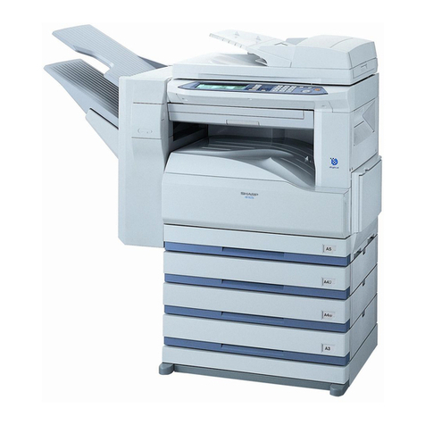
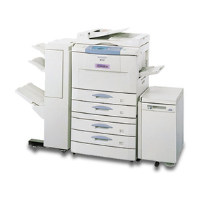
Sharp AR-LC1 User manual

SERVICE MANUAL
CODE: 00ZARLC1//A1E
DIGITAL COPIER OPTION
LARGE-CAPACITY
PAPER FEED TRAY
MODEL AR-LC1
SHARP CORPORATION This document has been published to be used
for after sales service only.
The contents are subject to change without notice.
Parts marked with "!" is important for maintaining the safety of the set. Be sure to replace these parts with specified
ones for maintaining the safety and performance of the set.
[ 1 ] OUTLINE OF THE PRODUCT . . . . . . . . . . . . . . . . . . . . . . . . . . 1-1
[ 2 ] SPECIFICATIONS . . . . . . . . . . . . . . . . . . . . . . . . . . . . . . . . . . . 1-1
[ 3 ] UNPACKING AND INSTALLATION . . . . . . . . . . . . . . . . . . . . . . 3-1
[ 4 ] EXTERNAL VIEW AND INTERNAL CONSTRUCTION . . . . . . 4-1
[ 5 ] OPERATING PRINCIPLE . . . . . . . . . . . . . . . . . . . . . . . . . . . . . 5-1
[ 6 ] DISASSEMBLY AND REINSTALLATION . . . . . . . . . . . . . . . . . 6-1
[ 7 ] ADJUSTMENT . . . . . . . . . . . . . . . . . . . . . . . . . . . . . . . . . . . . . . 7-1
[ 8 ] MAINTENANCE . . . . . . . . . . . . . . . . . . . . . . . . . . . . . . . . . . . . . 8-1
[ 9 ] TROUBLESHOOTING . . . . . . . . . . . . . . . . . . . . . . . . . . . . . . . . 9-1
[10] WIRING DIAGRAM . . . . . . . . . . . . . . . . . . . . . . . . . . . . . . . . . 10-1
[11] EXPLANATION OF THE CIRCUITS . . . . . . . . . . . . . . . . . . . . 11-1
PARTS GUIDE
CONTENTS

[1] OUTLINE OF THE PRODUCT
This paper feed unit stores about 3300 sheets of A4- or B5-size
paper to save the trouble of adding paper when a large amount of
copies is to be taken.
Note: If this large-capacity paper feed unit is to be installed, it is
required to install an optional single-stage paper feed desk
(AR-DE1) or special desk (AR-DD1).
AR-DE2 AR-LC1
[2] SPECIFICATIONS
(1) Paper feed capacity
Paper feed capacity 3300 sheets (64 g/m2or equivalent)
(2) Amount detection
Paper amount detection Provided (5-stage sensors including
empty detection)
Detector 0% (empty), ∼25%, ∼50%, ∼75%,
∼100%
Paper size detection None
(3) Paper size
Paper size A4/B5
Paper weight 56 ∼105 g/m2(14 ∼28 lbs) (Same as
the copier’s paper feed section)
(4) Size switching
Switching to be performed by service personnel
(5) Size detection
Size detection Setting by simulation
(6) Dehumidifying heater
Yes/No Yes
ON/OFF switch ON/OFF by dehumidification heater
switch on the copier
(7) Factory setting
Factory setting paper
size A4
Plate display A4
(8) Power supply
Power supply supplied by the copier
(DC 5 V, DC 24 V)
(9) Power consumption
Max. power consumption about 17.6 W
At stand-by about 1.2 W
(10) External view
External dimensions 325 (wide) ×536 (deep) ×572 (high)
mm
Weight about 32 kg
Case color Frosty gray
1 – 1

[3] UPACKING AND INSTALLATION
1. Unpacking
1 Upper cushion 2 Installation manual
3 LCC 4 Lower cushion
5 Packing case
2
1
1
3
5
4
4
2. Installation procedure
Parts included
Remove the power cord from the copier and then
perform the following procedure.
1. Mount the upper mounting plates and the mounting
plate.
Make 6 holes for mounting (indicated with ) on the copier and
lower part of the stand using a Phillips screwdriver, etc. and remove
burs using a flat-blade screwdriver, etc.Mount the upper mounting
plates using screws A (two for each plate).
Then remove 2 screws from the LCC cover on the copier and remove
the LCC cover.
Securing plate
(1 pc.)
Upper mounting plates
(2 pcs.)
Mounting plate
(1 pc.)
Connecting plate
(1 pc.)
Screws A (6 pcs.) Screw B (1 pc.) Screws C (2 pcs.)
Hole for mounting
Hole for mounting
Screws A
Screws A
Screws A
Screw
Screw
Upper
mounting plate
Upper
mounting plate
LCC cover
Mounting plate
3 – 1

2. Mount the connecting plate to the large capacity tray.
Note: Before mounting the connecting plate to the large capacity
tray, be sure to remove the 2 step screws for securing the
bottom plate.
Fit the connecting plate to the lower part of the large capacity tray
and mount the plate to the position indicated with A using screw B.
3. Fit the connecting plate of the large capacity tray to
the mounting plate of the stand.
Insert the connecting plate into the mounting plate of the stand while
lifting the large capacity tray a little.
After insertion, move the large capacity tray away from the copier to
check that the tray is locked.While the tray is locked, mount the
securing plate using 2 screws C.
4. Check and adjust the height of the large capacity tray.
Move the large capacity tray toward the copier and adjust the tray
and check it so that the rib of the large capacity tray is flush with the
axis of the mounting plate which has been mounted to the copier as
shown in the figure.
•If the axis is flush with the rib:
Push the large capacity tray toward the copier.
•If the axis is not flush with the rib:
Loosen the 2 screws of the installation adjuster mounting plate lo-
cated at the lower part of the large capacity tray and adjust as fol-
lows:
★If the rib is to the right of the axis
Turn the knob clockwise to adjust.
After adjustment, tighten the 2 screws of the installation adjuster
mounting plate.
★If the rib is to the left of the axis
Turn the knob counterclockwise to adjust.
After adjustment, tighten the 2 screws of the installation adjuster
mounting plate.
‚`
‚a
‚`
‚a
Screw B
Step screws
Connecting plate
1 2
Mounting plate
Connecting plate
Securing plate
Screws C
Top view
Axis Rib
Top view
Axis Rib
Knob
Screw
Top view
Axis Rib
Knob
Screw
3 – 2

5. Connect the connector of the large capacity tray.
Remove the connector cover securing screw for connection of the
large capacity tray relay harness connector and remove the connec-
tor cover.Then connect the large capacity tray relay harness connec-
tor to the connector of the copier and tighten the screw on the con-
nector to secure the connector.
6. Remove the feed table securing screw and securing
materials.
Pull out gently the paper tray of the large capacity tray until it
stops.Remove the feed table securing screw and 5 securing materials
which secure the feed table of the large capacity tray.
Push back gently the paper tray to its original position.
To use the large capacity tray without changing the paper size from
the factory default setting:
★Proceed to step 12 of this installation manual.
At this time, insert the power plug of the copier to an outlet and turn
the power switch to the "ON" position.
★Factory default setting: A4 size
The paper size can be switched only to the B5 size.
To use the large capacity tray after changing the paper size from the
factory default setting:
7. Remove the stopper from the paper tray.
Pull out gently the paper tray until it stops and remove the stopper
securing screw located on the lower part of the right side to remove
the stopper.
Then pull out again the paper tray until it stops.
8. Switch the rear end shaft.
Remove each rear end shaft securing screw (blue) which secures the
rear end shaft to the right side in the paper tray and remove the 2
rear end shafts.
Then fit the lower part of each removed rear end shaft to the mount-
ing hole of the feed table of the paper tray and secure the upper part
to the position with B5 indication using a securing screw (blue).
Securing screw
Connector cover
Screw
Connector
Securing materials
Securing materials
Feed table securing screw
Feed table
Stopper
Securing screw
Rear end shafts
Securing screw (blue)
Rear end shafts
Feed table Mounting holes
3 – 3

9. Switch the size of side plates F and R
Remove the screws which secure the upper and lower parts of side
plates F and R and remove side plates F and R.
Then fit the lower parts of side plates F and R to the position with B5
indication, position also the upper parts to the B5 size position, and
secure the plates using two screws (blue) for each plate.
10. Mount the stopper of the paper tray.
Push in the paper tray a little, mount the stopper which has been
removed in step 9, and secure it using the screw. At this time, check
that the pawl of the stopper is caught by the stopper block of the large
capacity tray.
Then push back gently the paper tray to its original position.
Paper size switching is complete here.
Insert the power plug of the copier to an outlet,
turn the power switch to the "ON" position and
then perform the following procedure.
11. Register the paper size.
•Register the paper size with the key operation of the copier.
The LCC size selection window will be displayed in the message
display with the operation above.
Select the number of the size to be registered in the message dis-
play, enter the number using the keys on the operation panel and
press the OK key to register it.
Then turn the power switch to the "OFF" position and then to the
"ON" position again.
12. Adjust the center position.
Since adjustment has been made at shipment, adjustment is basically
not needed. However, if the center should be displaced, adjust it
using the procedure below.
Make a copy. If the center is displaced as shown in Fig. 1 or Fig. 2,
pull out gently the paper tray until it stops.
Then, loosen the 2 screws at portion a which secure the tray lock
plate and the 8 screws at portion b (right and left sides) which secure
the tray cover unit to the frame and adjust the center position using
the procedure below.
Side plate R
Screws (blue)
Screws (blue)
Side plate F
Stopper block
Pawl
Stopper
Screw
2 6 2C
P
Left side Right side
Portion b
Portion a
Tray cover unit
Portion a
Direction A
Direction B
Scale (pitch in mm)
Tray lock plate
Portion b
3 – 4
•In case of Fig. 1:
Move the tray lock plate in direction A by the length of displacement,
tighten the 2 screws at portion a and then the 8 screws at portion b,
and make a copy again to check that the center is not displaced.
•In case of Fig. 2:
Move the tray lock plate in direction B by the length of displacement,
tighten the 2 screws at portion a and then the 8 screws at portion b,
and make a copy again to check that the center is not displaced.
Fig. 1
Center line of paper
Center of image (first image)
Center line of paper
Center of image (first image)
Fig. 2
3 – 5

[4] EXTERNAL VIEW AND INTERNAL CONSTRUCTION
1. External view
1. Tray down button/lamp
The tray can be opened by pressing the button. Use this button when adding paper or paper jam occurs.
2. Main parts
No. Name No. Name
1 Transport roller 2 Paper feed roller
3 Hitching roller 4 Reversion roller
5 Tray 6 Lift-up unit
7 Encoder 8 Height adjustment unit
9 Caster
1
123
4
5
6
7
8
9
4 – 1

PWB location
No Name Function and operation
1 Control PWB Controlling LCC
2 Tray switch PWB Tray lifting switch
Motor, clutch, solenoid, motor
Motor
No. Symbol Name Function and operation
1 LPFM Paper feed and transport motor Driving paper feed and transport systems
2 LLM Lift-up motor Driving tray lifting up
Clutch and solenoid
No. Symbol Name Function and operation
3 LPFC Paper clutch Driving paper clutch
4 LPFS Pick-up solenoid Operating pick-up roller
Motor
No. Symbol Name Function and operation
5 HT Dehumidifying motor Dehumidifying paper and preventing condensation of dew.
12
4 LPFS
3 LPFC
1 LPFM
2 LLM
5 HT
4 – 2

Sensor, detector location
No. Symbol Name Function and operation
1 LPFD Transport detector Detecting paper discharge
2 LLSW Upper limit lock switch Detecting tray upper limit lock (Shutting off motor as a safety device.)
3 LPED Paper detector Detecting the presence of paper
4 LUD Upper limit detector Detecting tray upper limit position
5 LRES Encoder sensor Controlling lifting up
6 LDD Lower limit detector Detecting tray lower limit position
7 LTOD Copier connection detector Detecting connection to copier
1 LPFD
7 LTOD
5 LRES
6 LDD
2 LLSW 4 LUD
3 LPED
4 – 3

[5] OPERATING PRINCIPLE
1. Lift-up operation
When the copier is powered up, the main circuit checks the detection
state of each sensor. If the upper limit detector (LUD) is OFF, the
lift-up motor is turned on to elevate the tray till the position which
allows paper feed (upper limit detector ON).
1 Upper limit detector (LUD)
2 Paper detector (LPED)
3 Paper tray
4 Lower limit detector (LDD)
2. Lift-down operation
If no paper is present after paper feed, the main circuit detects the
ON condition of the paper detector (LPED) and turns on the lift-up
motor to descend the tray till the position at which the lower limit
detector (LDD) turns on (the tray can be drawn out).
The tray switch PWB indication LED blinks while the tray is lifting or
descending.
3. Paper feeding
When copying is started, the transport motor (LPFM) starts. Then, the
pick-up solenoid (LPFS) and paper feed clutch (LPFC) turn on. When
the solenoid is turned on, the paper hitching roller is lowered to
contact the paper.
When the clutch is turned on, both the paper feed roller and the
hitching roller rotate to start paper feeding. The paper is sent through
the transport sensor (D) to the copier.
1 Paper feed roller clutch (LPFC)
2 Paper hitching roller
3 Paper feed roller
4 Pick-up solenoid (LPFS)
1,2
3
4
LLMD
LLMU
LDD
LUD
5msec
30msec
Lifting (no paper, lifting from bottom to top)
Elevation starts Reversion starts
About 100 msec
LLMD
LLMU
LDD
LUD
100msec
30msec
Lifting (no paper, descending from top to bottom)
Descending starts
1
2
4
3
4
2
3
LPFM
LPFC
LPFS
LPFD
Paper feed (Letter size, A4, B5)
Job start signal reception
Paper feed start signal reception
Paper feed finish
signal transmission
Job END signal
reception
5 – 1

[6] DISASSEMBLY AND ASSEMBLY
1. Transport section (Paper feed roller) 2. Paper feed section
A. Paper feed unit
1)
2)
1)
1)
2)
2)
3)
4)
6)
5)
5)
7)
1)
1) 2)
1)
2)
3)
2) 2)
6 – 1

B. Paper feed roller, take-up roller
Note 1: When installing the paper feed roller, be careful of the install-
ing direction. …*1
Note 2: When installing the paper feed clutch, check that the clutch
stopper is caught by the pawl. …*2
C. Reverse roller
3. Control PWB
1)
2)
3)
4)
5) 6)
6)
2
1
rib
1)
2)
3)
1)
2)
6 – 2

4. Paper feed/transport motor
5. Lift-up motor
1)
2)
3)
1)
2)
3)
2)
2)
6 – 3

[7] ADJUSTMENT
Lift-up motor (LLM) installing position adjustment
Install the motor so that the lift-up motor shaft comes to the center of
the insertion port of the lift-up motor installing plate shaft.
7 – 1

[8] MAINTENANCE
Make sure to disconnect the phone line/communication cable from the copier before performing maintenance, because receiving the signal during
maintenance is dangerous.
1. Maintenance system table
F: cleaning ★: lubrication ×: checking (cleaning, replacement or adjustment as required)
Unit name Name 80K 160K 240K 320K Remarks
Driving section Paper feed and transport gear ★★★★
Lift-up gear ★★★★
Transport section Transport roller FFFF
Paper guide FFFF
Paper feed section Paper feed roller ××××Replacement period (80K or 2 years)
Reversion roller ××××Replacement period (80K or 2 years)
Hitching roller ××××Replacement period (80K or 2 years)
Torque limiter ××××
2. Details of maintenance
A. Driving section
No. Name Operation Cycle Remarks
1 Paper feed and transport gear Lubrication 80K
2 Lift-up gear Lubrication 80K
2
1
8 – 1

B. Paper feed and transport section
No. Name Operation Cycle Remarks
1 Transport roller Cleaning 80K
2 Paper feed guide Cleaning 80K
3 Paper feed roller Check *80K Replacement period (80K or 2 years)
4 Reversion roller Check *80K Replacement period (80K or 2 years)
5 Hitching roller Check *80K Replacement period (80K or 2 years)
6 Torque limiter Check *80K Replacement period (80K or 2 years)
4
6
3
5
2
1
1
8 – 2

[9] TROUBLESHOOTING
1. Trouble code list
Trouble
code Trouble Remarks Trouble
detection
U6 09 LCC lift motor trouble — LCC
20 LCC communication trouble — PCU
21 LCC transport motor trouble — LCC
22 LCC 24V power trouble — LCC
2. Self-diagnostics
Trouble
code Details of trouble
U6 09 Content LCC lift motor trouble
Detail LCC lift motor trouble
Cause Sensor defective
LCC control PWB defective
Gear broken
Lift motor defective
Check and
remedy Check sensor operation with SIM4-2.
Check lift motor operation with
SIM4-3.
20 Content LCC communication trouble
Detail Communication trouble with LCC
Error at communication line test
when power is turned on or leaving
SIM.
Cause Connector: Defective connection of
harness or broken wire
LCC control PWB defective
Control PWB (PCU) defective
Malfunction due to noise
Check and
remedy Can be reset by turning on and off
power supply.
Check communication line connector
and harness.
21 Content LCC transport motor trouble
Detail LCC transport motor operation
trouble
Cause Motor lock
Motor speed error
Overcurrent to motor
LCC control PWB defective
Check and
remedy Check transport motor operation with
SIM4-3.
22 Content LCC24V power supply error
Detail No power supply (24V) to LCC
Cause Connector: Harness connection
defective or broken wire
LCC control PWB defective
Power supply unit defective
Check and
remedy Check power supply line connector
and harness.
Check for 24V at power supply unit
and LCC control PWB
*Displayed on the control panel of the copier
If a trouble occurs, check the cause of the trouble using the following
flow charts.
N: No Y: Yes
A. LCC does not operate
N
Y
N
Y
N
Y
N
A
F
Y
DB
Is interface
harness properly
connected?
+5V between
CN-B-7 and 8 of
control PWB?
+24V between
CN-B9 and 10 of
control PWB?
Ready state after
setting paper?
Connect properly.
Check and if necessary
replace harness.
Check and if necessary
replace harness.
9 – 1

B. Lift motor error C. Transport motor error
D. Sensor error
N
Y
N
Y
N
Y
N
Y
N
Y
N
Y
Y
N
B
D
Is fuse blown out?
Is load on motor
shaft normal?
Is upper limit
sw on paper feed
UN turned on?
Is harness
connected properly?
Does motor rotate
even slightly?
Is motor
encoder sensor
output normal?
Replace fuse.
Check mechanical load
and driving system, and
remove any foreign matter.
Lower tray until upper
limit switch turns off.
Connect harness properly.
Check harness and if
necessary replace.
Is voltage
applied to motor
connector?
Check and if necessary
replace motor.
Check and if necessary
replace control PWB.
C
N
Y
N
Y
N
Y
N
Y
Y
N
Is load on motor
shaft normal?
Is harness
connected properly?
Does motor rotate
even slightly?
Is motor encoder
output normal?
Is voltage applied to
motor connector?
Check and if necessary
replace motor.
Check and if necessary
replace control PWB.
Connect harness properly.
Check and if necessary
replace harness.
Check mechanical load
and driving system, and
remove any foreign matter.
D
N
Y
Check for
sensor mounting.
Is harness connected
properly?
Replace control PWB.
Check mounting and if
necessary replace harness.
9 – 2

E. Clutch and solenoid error
G. Paper jam
F. No paper is fed
N
Y
N
Y
N
Y
E
Is each load
properly installed?
Conductivity
between coils of
each load?
Conductivity
between connectors
and terminals?
Replace control PWB.
Check mounting and if
necessary replace.
Replace clutch or solenoid.
Check and if necessary
replace harness.
N
Y
G
N
Y
N
Y
N
Y
Y
N
N
Y
Y
D
Is improper
paper used?
Foreign matter
in paper path?
Is transfer
sensor normal?
Sheets are fed
one by one?
Replace
control PWB.
Use specified
paper.
Remove foreign
matter.
Is paper feed
unit properly
assembled?
Is separation
roller contaminated
with paper
dust?
Replace
separation roller.
Check paper
feed unit and if
necessary
replace.
Clean.
N
Y
N
Y
N
Y
N
Y
N
Y
F
C
E
E
Is paper feed
rollers contaminated
with paper dust?
Does roller rotate?
Does pick-up
roller drop at paper
feeding?
Does
pick-up roller
rotate in paper feed
direction at paper
feeding?
Is improper
paper used?
Replace control PWB.
Check mechanical load and
driving system. Remove any
foreign matter and clean.
Use specified paper.
9 – 3
Table of contents
Other Sharp Copier manuals

Sharp
Sharp AR-BC260 User manual

Sharp
Sharp AR-164 User manual

Sharp
Sharp AR-650 User manual

Sharp
Sharp AR-5132 User manual

Sharp
Sharp AR-FX4 User manual

Sharp
Sharp AR-201 User manual

Sharp
Sharp AR-151 User manual

Sharp
Sharp 00ZSF1116/A1E User manual

Sharp
Sharp AR-C260 Programming manual

Sharp
Sharp SF-1014 User manual

Sharp
Sharp MX-M363U Installation and operating manual

Sharp
Sharp IMAGER AR-5316 User manual

Sharp
Sharp SF-2530 User manual

Sharp
Sharp AR-121E User manual

Sharp
Sharp AR-280 User manual

Sharp
Sharp AL-1642CS User manual

Sharp
Sharp AR-RP6 User manual

Sharp
Sharp MX-2300N Guide User instructions

Sharp
Sharp MX-C382SC Guide

Sharp
Sharp AR-287 User manual