AR-FX7 SPECIFICATIONS 2 - 2
(6) Memory transmission/direct transmission
(7) Broadcast function
(8) Scan specification
(9) Priority function
(10) Multiple message transmission
(11) Rotation transmission
(12) Book document transmission
(13) Finish stamp
(14) Bulletin board (remote transmission, polling
transmission functions)
6. Reception function system
(1) Reception mode
(2) Zoom reception
(3) Memory reception function
(4) Received data skip output
(5) Transfer
(6) Specified number reception
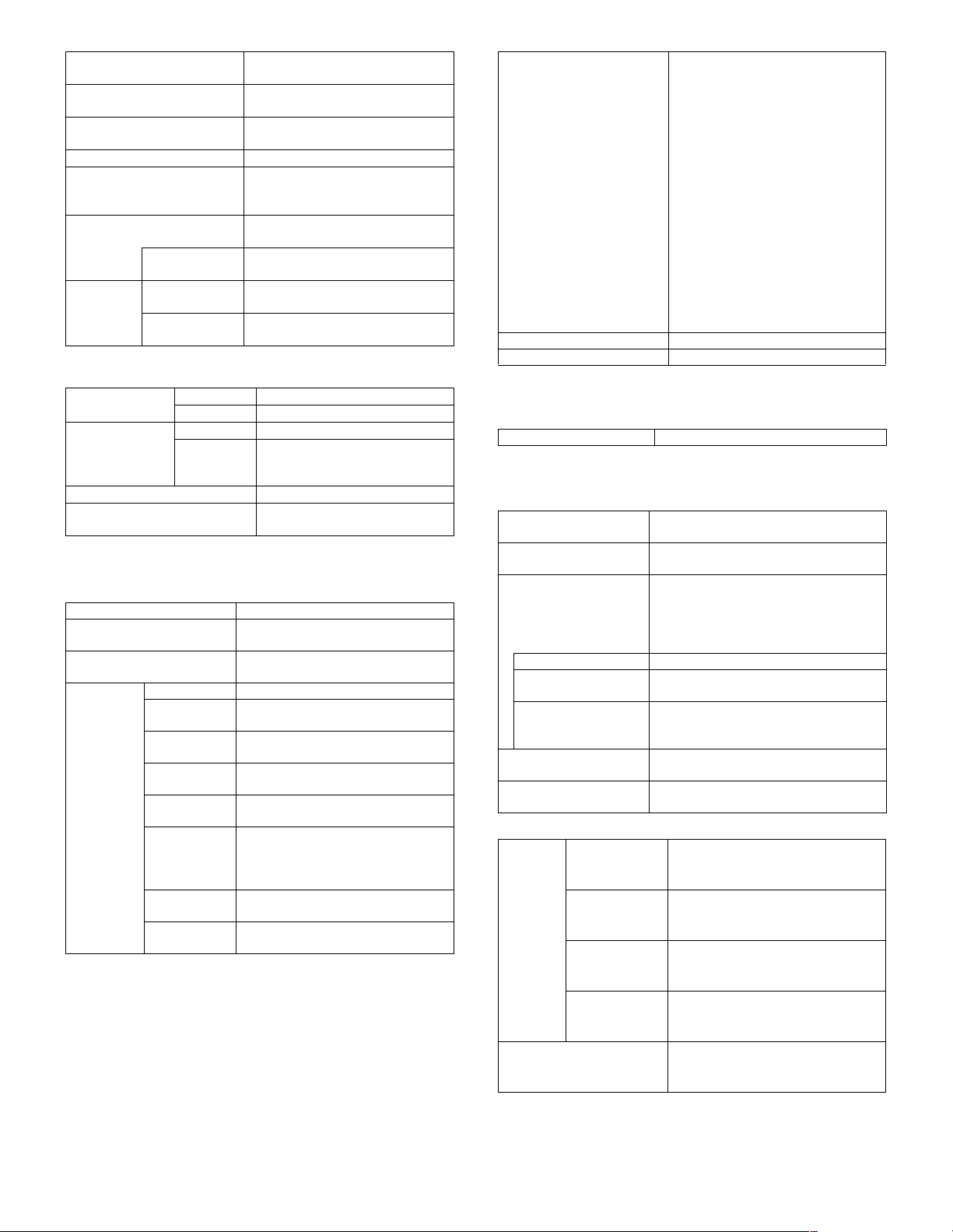
Memory transmission YES
Number of reservation
to be set
Max. 50 items
Process in memory full Transmission cancel or only
scanned data transmission
Quick online transmission YES (Enable/Disable setup by key
operator program)
Direct transmission YES (100 pages from RSPF, only 1
page from OC)
Default setup Set by key operator program
Broadcast
transmission
Number of
destinations
200 destinations (When group
dialing is used, the number of
other parties registered to group
dialing is added.)
Transmission
method
10-key, rapid key dialing, group
key, next address key
Usable dial 10-key entry, rapid key dialing,
group key dialing.
However, an address including
sub address of 10-key entry
registered cannot be used.
Group dialing Transmitted by group dialing
registered to rapid key dialing
Relay
broadcast
transmission
Instructing
station
Only from the machine having
Sharp relay broadcast
instructing transmission function
Relay station Only from the machine having
Sharp relay broadcast
transmission function
Multi-stage relay NO
Number of relay
groups
10 groups
F code relay broadcast
instruction (relay broadcast
instruction function)
YES
F code relay broadcast (relay
function)
YES
Confidential transmission (Sharp
machine mode) (Other party)
Only Sharp machine having
confidential function
Confidential transmission (F code
communication) (Other party)
F code support machine
Page division YES (Allowed only from OC)
Applicable size: A3/B4/A4R
Page linkage NO
Transmission reservation interrupt YES (check by job status key)
Broadcast interrupt YES (by direct transmission)
Multiple message transmission NO
Paper size A4 →A4R, A5R →A5,
8.5 x 11 → 8.5 x 11R
Transmission method By OC mode
NO
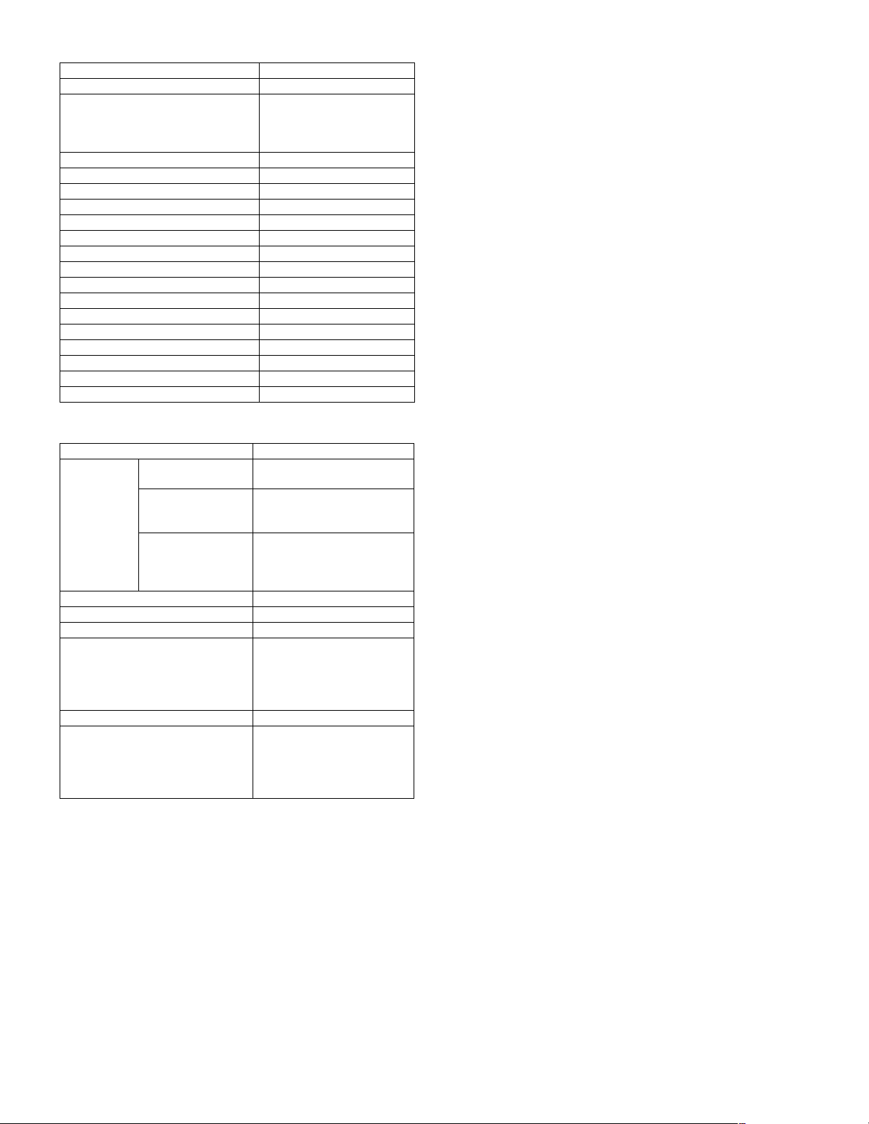
Bulletin board
(remote
transmission)
YES
Polling protection
function
Check by other party’s number YES
Check by matching of system number
(user’s own machine), ID number
(other party’s machine) (between
Sharp machines only)
YES
F code bulletin
board
YES
F code bulletin
board box
Registered up to 10 boxes
F code bulletin
board box name
Registered up to 36 letters (18 letters are
displayed)
Default setup Automatic reception (Reception
state switchable)
Automatic
reception
Automatic
reception setup
YES
Number of calls 0 to 9 times (Factory default 2
times)
Non-call reception Allowed by setting the number of
calls to 0.
Manual reception setup YES
Setup for switching to automatic
reception
0 to 9 times (Factory setup 0
time) (France only)
Auto reduction setup in letter
reception
NO
Auto reduction setup in A3
reception (A3 RX REDUCE)
NO
Answering machine connection NO
Reception mode time switch NO
Reception data print condition
setup
Set whether the received data
are reduced or divided to print,
by the key operator program.
Auto reduction print on the
paper size
YES (ON/OFF by key operator
program)
Memory delayed receiving Only when output is disabled.
Forced memory receiving NO
YES
Transfer destination
registration
YES (Registered by key operator
program)
Transfer procedure YES (Operated by function menu)
Only designated number
receiving enabled.
NO
Reception reject setup
(ANTI JUNK FAX)
YES (ON/OFF by key operator
program)
Registration of the
numbers to be rejected
50 items (up to 20 digits each)
Registered by key operation program.