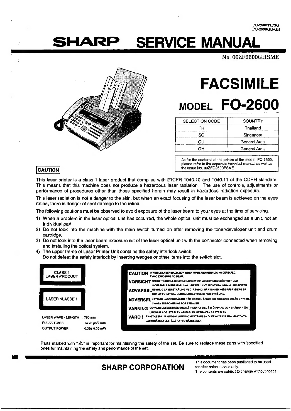
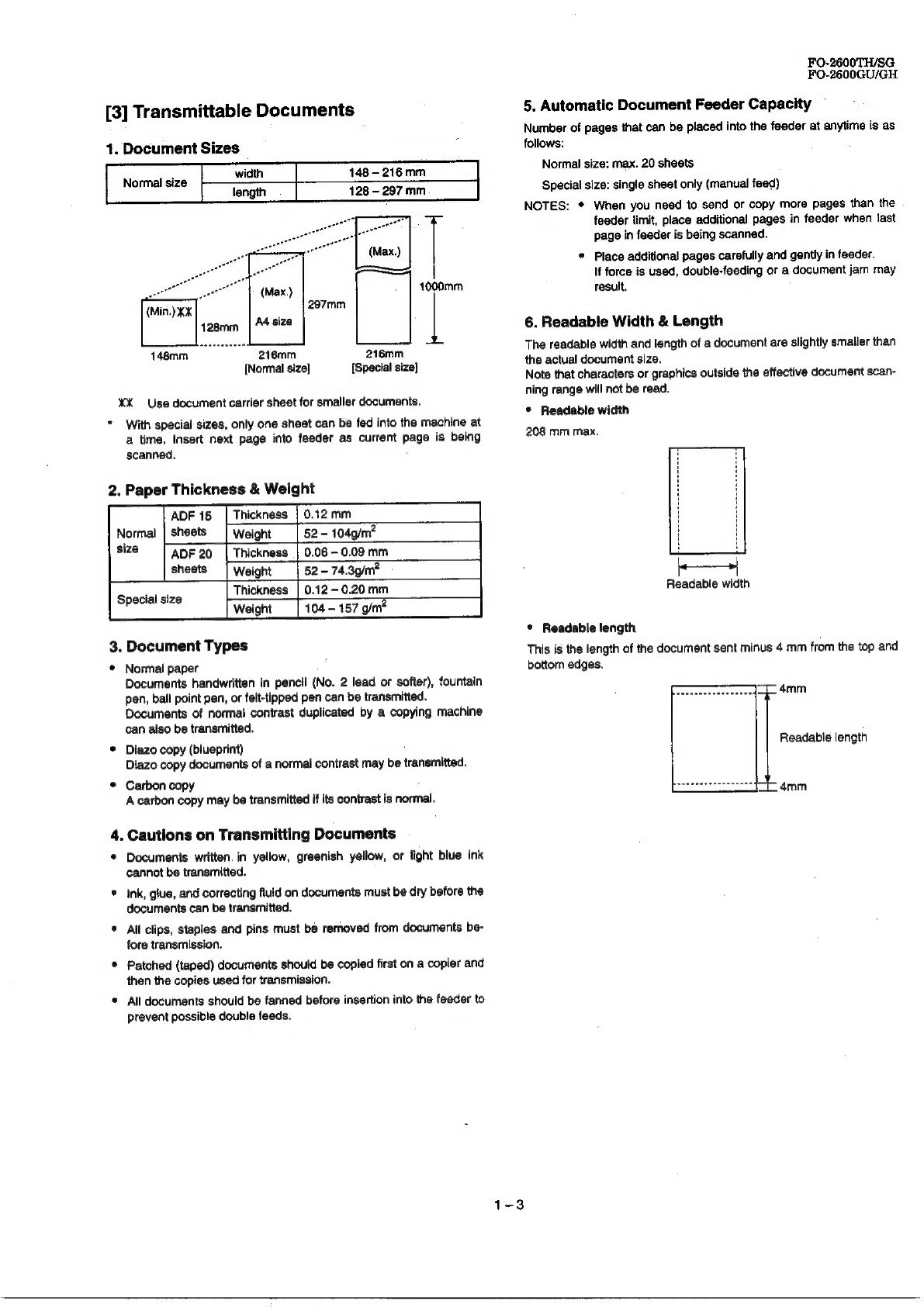
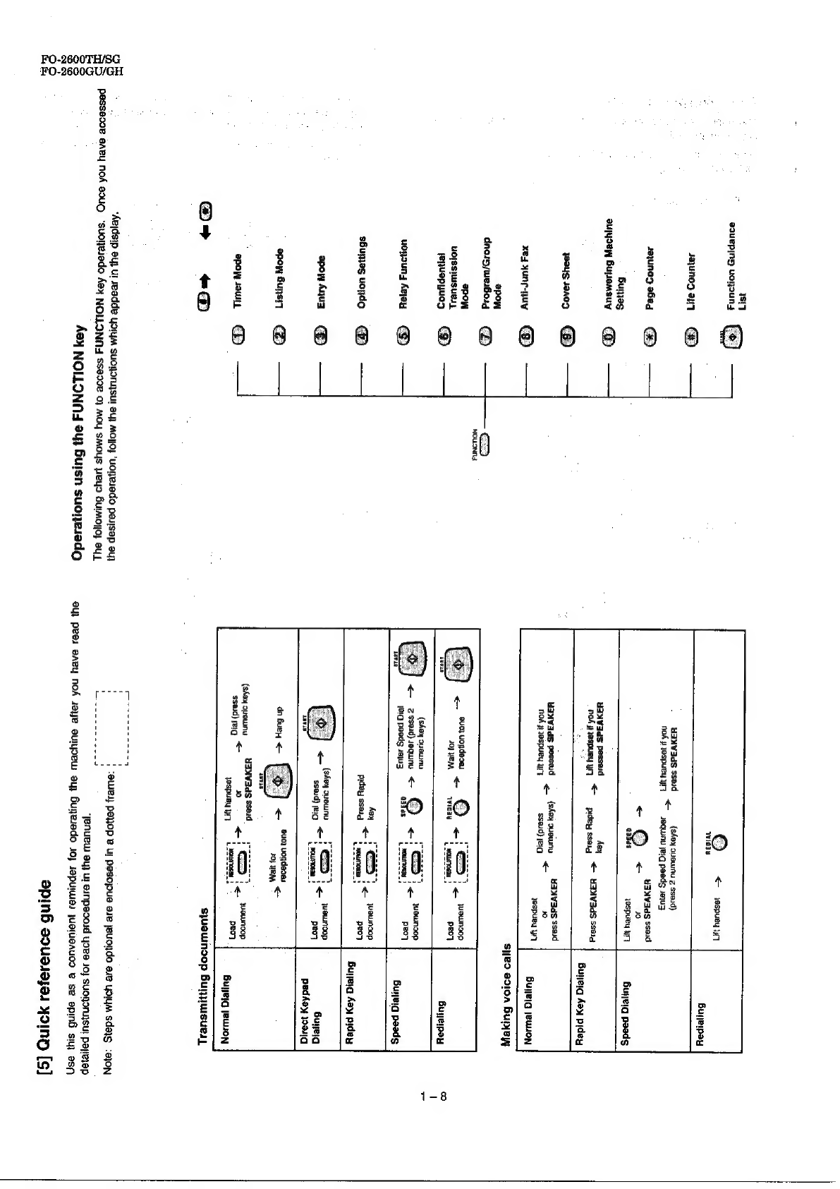
Sharp FO-2600 User manual

FO-2600TH/SG,
FO-2600GU/GH
SHARP
_
SERVICE
MANUAL
No.
00ZF2600GHSME
FACSIMILE
mopeEL
FO-2600
SELECTION
CODE
COUNTRY
TH
Thailand
SG
Singapore
(et
GU
General
Area
GH
General
Area
As
for
the
contents
of
the
printer
of
the
model
FO-2600,
x
please
refer
to
the
separate
technical
manual
as
well
as.
CAUTION
the
issue
No.
OOZFO2600PSME.
This
laser
printer
is
a
class
1
laser
product
that
complies
with
21CFR
1040.10
and
1040.11
of
the
CDRH
standard.
This
means
that
this
machine
does
not
produce
a
hazardous
laser
radiation.
The
use
of
controls,
adjustments
or
performance
of
procedures
other
than
those
specified
herein
may
result
in
hazardous
radiation
exposure.
This
laser
radiation
is
not
a
danger
to
the
skin,
but
when
an
exact
focusing
of
the
laser
beam
is
achieved
on
the
eyes
retina,
there
is
danger
of
spot
damage
to
the
retina.
The
following
cautions
must
be
observed
to
avoid
exposure
of
the
laser
beam
to
your
eyes
at
the
time
of
servicing.
1)
When
a
problem
in
the
laser
optical
unit
has
occurred,
the
whole
optical
unit
must
be
exchanged
as
a
unit,
not
an
individual
part.
2)
Do
not
look
into
the
machine
with
the
main
switch
turned
on
after
removing
the
toner/developer
unit
and
drum
cartridge.
3)
Do
not
look
into
the
laser
beam
exposure
slit
of
the
laser
optical
unit
with
the
connector
connected
when
removing
and
installing
the
optical
system.
4)
The
upper
frame
of
Laser
Printer
Unit
contains
the
safety
interlock
switch.
Do
not
defeat
the
safety
interlock
by
inserting
wedges
or
other
items
into
the
switch
slot.
SICHEAHE!
TSVERAIEGELUNG
0
BERERU
CKT.
NICHT
DEM
STRAHL
AUSSETZEN.
LASER
PRODUCT
ADVARSELYS™NUG
LasensTRALING
Veo
ABniNG.
NAR
SIKKERHEOSAFBAYDERE
ER
UDE
AF
FUNKTION.
UNDGA
UDSAETTELSE
FOR
STRALING.
ADVERSEL,
USYNtIG
LasenstRALinG
NAR
CEKSEL
APNES
0G
SIKKEAHEDSLAS
BRYTES.
UNNGA
EKSPONERING
FOR
STRALEN.
VARNING
°SYNLIG
LasersTRALNiNG
N&R
DENNA
DEL
AAO
PPNAD
OCH
SPARRAR
AR
URKOPPLADE.
STAALEN
AR
FARLIG.
BETRAKTA
EJ
STAALEN.
VARO
|
AVATTARSSA
JA
SUQJALUKITUS
OHITETTAESSA
OLET
ALTTHNA
NAKYMATONTA
LASERSATEILYLLE.
ALA
KATSO
SATEESEEN.
CAUTION
!NVISOLE
LASER
RADIATION
WHEN
OPEN
AND
INTERLOCKS
DEFEATED.
VOID
EXPOSURE
TO
BEAM.
VORSICHT
UNGicHTAARe
LASERSTAAHLUNG
WENN
ABDECKUNG
GEO
FFNET
UND
LASER
WAVE
-LENGTH
:
780mm
PULSE
TIMES
114.26
ps/7
mm.
OUTPUT
POWER
10.352
0.05
mw
Parts
marked
with
"
A\“
is
important
for
maintaining
the
safety
of
the
set.
Be
sure
to
replace
these
parts
with
specified
ones
for
maintaining
the
safety
and
performance
of
the
set.
This
document
has
been
published
to
be
used
SHARP
CORPORATION
for
after
sales
service
only.
The
contents
are
subject
to
change
without
notice.

FO-2600TH/SG
FO-2600GU/GH
la
CONTENTS
CHAPTER
1.
GENERAL
DESCRIPTION
[1]
Specifications
...
2.6...
eee
tne
t
ete
1-1
[2]
Operation
Panel...
6.6...
eee
eee
tenet
eee
eens
1-2
[3]
Transmittable
Documents
.......
2
cece
cece
teen
een
e
eens
1-3
[4]
Installation
0.0.6.
teen
teen
een
e
es
1-4
[5]
Quick
reference
guide
20.0.2...
c
cece
cence
renee
teen
eet
e
nee
es
1-8
CHAPTER
2.
ADJUSTMENTS
(1)
Adjustments
00.0...
0
6.
cee
eee
renee
eee
tenes
2-1
[2]
Diagnostics
and
service
soft
switchs
....
66.6.6
6
eect
eee
neers
2-2
[3]
Troubleshooting
....
6.6...
e
cee
een
ee
ere
ees
2-20
[4]
Error
code
table
60.0.6...
cece
cece
ee
teeters
2-21
CHAPTER
3.
MECHANICAL
DESCRIPTION
[1]
Mechanical
description
.......
06.0
eee
e
eee
eeet
eee
et
etn
ent
nes
3-1
[2]
Disassembly/assembly
procedures
.....
16...
eee
e
eee
e
ete
e
tenes
3-3
CHAPTER
4.
DIAGRAMS
[1]
Block
diagram
2.6.60.
teen
nen
e
etn
nee
4-1
[2]
Wiring
diagram
26.6...
cece
eee
nee
ne
nee
ere
teens
4-2
{3]
Point
to
point
diagram
and
connector
signal
name
...
6.6...
e
eee
eet
4-3
CHAPTER
5.
CIRCUIT
DESCRIPTION
[1]
Circuit
description
6.6.6...
eee
ene
nett
tnt
ener
n
nee
5-1
{2]
Control
PWB
description
........
Wes
ae
tae
oy
ekale
Siw
APah
Seeeeb
te
went
AGEs
seein
uth
tose
a
teeleen
5-2
{3]
Description
of
CCD
board
2.6.6.6
cece
reenter
tne
e
enn
es
5-12
[4]
Description
of
TELILIU
oo.
eee
ence
eee
n
tere
teen
ets
5-12
[5]
Description
of
power
supply...
6.6.
e
ee
eee
eee
eect
e
enter
e
tees
5-16
CHAPTER
6.
CIRCUIT
SCHEMATICS
AND
PARTS
LAYOUT
[1]
Control
circui/PWB
o0
6.
ete
en
eens
6-1
{2]
TEL/LIU
Circui/PWB
.6
0...
ete
een
ene
een
n
eee
tee
6-10
[3]
PCU
circuit/PWB
000.
e
teen
tenn
ene
eens
6-22
[4]
Power
supply
circuit/PWB
.
1.0.0.6
0
6.
cee
eet
ene
nen
teen
eee
6-24
[5]
CCD
circui/PWB
0.06
ee
ete
net
etn nen
e
tenes
6-26
[6]
Operation
panel
circui/PWB
2...
eee
ee
tenes
6-27
[7]
LCD
circui/PWB
0.6
ce
ene
enn
eens
6-29
CHAPTER
7.
OPERATION
FLOWCHART
[1]
Flowchart...
0.
ee
eet
enn
eee
eee
es
7-1
[2]
Power
on
sequence...
6...
eee
ee
eee
teen
tenes
7-7
CHAPTER
8.
OTHERS
[1]
Service
Tools
6...
eee eee
e
ene
eens
8-1
[2]
IC
signal
name...
66.
ee
ete
ne
nee
etna
8-6
[3]
Option
(Memory
upgrade
PWB
FO-1ME)
.......--
eee
cece
eee
eee
ee
8-13
PARTS
GUIDE

CHAPTER
1.
GENERAL
DESCRIPTION
[1]
Specifications
Applicable
telephone
line:
Compatibility:
Configuration:
Compression
scheme:
Scanning
method:
Resolution:
Display:
Reception
modes:
Modem
speed:
Transmission
time*:
Effective
recording
width:
input
document
size:
Public
switched
telephone
_
net-
work/PBX
i
ITU-T
(CCITT)
G3
mode
Half-duplex,
desktop
transceiver
Modified
Huffman
and
Sharp
special
mode
Flat-bed,
solid-state
CCD
Horizontal:
8
dotsimm
Vertical:
Standard
—
3.85
lines/mm
Fine/Halftone
—
7.7
lines/mm
Super
fine-15.4
lines/mm
7
x
§-dots,
1
line
by
16-digit
display
Auto/Manual/Answering
machine
9600
bps
with
automatic
fallback
to
7200,
4800,
or
2400
bps
Approx.
13
seconds.
{Sharp
special
mode)
203
mm
(average)
Automatic
feeding:
Width
-
148
to
216
mm
Length
-
128
to
356
mm
Manual
feeding:
Width
~
148
to
216
mm
Length
—
128
to
1000
mm
Effective
scanning
width:
Automatic
document
feeder:
Haiftone
(gray
scale):
Contrast
control:
Copy
function:
Telephone
function:
Power
requirements:
Operating
temperature:
Power
consumption:
Dimensions:
Weight:
FO-2600TH/SG
FO-2600GU/GH
210
mm
max.
20
sheets
max.
32
levels
Automatic/Dark
selectable
Single/Multi-copy/Sort-copy
(99
cop-
ies/page)
Standard
{cannot
be
used
if
power
fails)
Standard
local
voltage
40-30°C
Stand-by:.7
W
Maximum:
680
W
Width:
360
mm
Depth:
412
mm
Height:
169
mm
Approx.
7.2
kg
*
Based
on
ITU-T
(CCITT)
Test
Chart
#1
at
standard
resolution
in
Sharp
special
mode,
excluding
time
for
protocol
signals
(i.e.,
ITU-
T
phase
C
time
only).
<IMPORTANT
PLEASE
READ
FIRST>
To
avoid
problems
with
supplies,
please
don’t
use
supplies
from
other
units.
Please
use
new
supplies,
when
supply
changes
are
required.

FO-2600TH/SG.
FO-2600GU/GH
[2]
Operation
Panel
PAPER
CHECK
light
RESOLUTION
key
This
light
comes
on
when
Press
this
key
to
adjust
the
you
are
out
of
paper
or
when
resolution
and
contrast,
BROADCAST
key
the
paper
size
setting
is
before
sending
or
copying
Press
this
key
to
send
a
a
document.
document
to
a
group
of
incorrect.
receiving
fax
machines.
MEMORY
key
Press
this
key
to
scan
a
document
into
memory
before
transmitting
it.
SEARCH
DIAL.
key
Press
this
key
to
search
for
an
automatic
dialling
number.
Toner
empty
indicator
This
blinks
when
the
imaging
cartridge
is
near
the
end
of
its
life,
and
lights
steadily
when
it
must
be
replaced.
Service
indicator
FUNCTION
key
Press
this
key
to
select
various
special
functions.
Liquid
crystal
display
This
displays
various
messages
during
RECEPTION
MODE
key
Press
this
key
to
select
This
lights
when
a
operation
and
problem
occurs
which
programming.
the
mode
of
reception,
must
be
fixed
by
a
service
engineer.
YOUTEZ
Reception
mode
lights
One
of
these
lights
will
come
on
to
indicate
which
COPY
ke:
Press
thie
key
reception
mode
has
been
to
make
a
copy
selected.
of
a
document.
STOP
key
Press
this
key
to
stop
operations
CC
Ke ae
es
es
ee
a
a)
before
they
are
CA
Ga
a
ss
es
ee es
es)
START
key
Number
keys
Use
these
keys
to
dial
Press
this
key
to
Rapid
Keys
numbers,
and
enter
send
or
receive
a
Press
one
of
these
keys
to
en
dial
a
fax
or
voice
number
SPEED
key
automatically.
(Note
that
numbers
and
letters
during
number/name
storing
procedures.
Press
this
key
to
dial
you
must
attach
the
Rapid
HOLD
key
SPEAKER
key
a
2-digit
Speed
Dial
Meenas
Press
this
key
to
put
the
Press
this
key
to
dial
number.
other
party
on
hold
during
a
@
number
without
REDIAL
key
telephone
coversation.
picking
up
the
handset.
Press
this
key
to
automatically
redial
the
last
number
dialled.

[3]
Transmittable
Documents
1.
Document
Sizes
148
-
216mm
128
—
297
mm
width
length
Normal
size
1000mm
216mm 216mm
[Special
size]
(Normal
size]
XX
Use
document
carrier
sheet
for
smaller
documents.
*
With
special
sizes,
only
one
sheet
can
be
fed
into
the
machine
at
a
time.
Insert
next
page
into
feeder
as
current
page
is
being
scanned,
2.
Paper
Thickness
&
Weight
0.12
mm
52
-
104g/m*
0.06
-
0.09
mm
52
—
74,3g/m?
0.12
—
0.20
mm
104
-
157
gim*
AOF
15
sheets
ADF
20
sheets
Thickness
Weight
Thickness
Weight
Thickness
Weight
Special
size
3.
Document
Types
*
Normal
paper
.
Documents
handwritten
in
pencil
(No.
2
lead
or
softer),
fountain
pen,
ball
point
pen,
or
felt-tipped
pen
can
be
transmitted.
Documents
of
normal
contrast
duplicated
by
a
copying
machine
can
also
be
transmitted.
©
Diazo
copy
(blueprint)
Diazo
copy
documents
of
a
normal
contrast
may
be
transmitted.
*®
Carbon
copy
A
carbon
copy
may
be
transmitted
if
its
contrast
is
normal.
4.
Cautions
on
Transmitting
Documents
©
Documents
written.
in
yellow,
greenish
yellow,
or
light
blue
ink
cannot
be
transmitted.
®
Ink,
glue,
and
correcting
fluid
on
documents
must
be
dry
before
the
documents
can
be
transmitted.
*
All
clips,
staples
and
pins
must
be
removed
from
documents
be-
fore
transmission.
©
Patched
(taped)
documents
should
be
copied
first
on
a
copier
and
then
the
copies
used
for
transmission.
*
All
documents
should
be
fanned
before
insertion
into
the
feeder
to
prevent
possible
double
feeds.
FO-2600TH/SG
FO-2600GU/GH
5,
Automatic
Document
Feeder
Capacity
~
Number
of
pages
that
can
be
placed
into
the
feeder
at
anytime
is
as
follows:
Normal
size:
max.
20
sheets
Special
size:
single
sheet
only
(manual
feed)
NOTES:
®
When
you
need
to
send
or
copy
more
pages
than
the
feeder
fimit,
place
additional
pages
in
feeder
when
fast
page
in
feeder
is
being
scanned.
©
Place
additional
pages
carefully
and
gently
in
feeder.
If
force
is
used,
double-feeding
or
a
document
jam
may
result.
6.
Readable
Width
&
Length
The
readable
width
and
length
of
a
document
are
slightly
smaller
than
the
actual
document
size.
Note
that
characters
or
graphics
outside
the
effective
document
scan-
ning
range
will
not
be
read.
©
Readable
width
208
mm
max.
Readable
width
©
Readable
length
This
is
the
length
of
the
document
sent
minus
4
mm
from
the
top
and
bottom
edges.
an
4mm
Readable
length
y
4mm

FO-2600TH/SG
FO-2600GU/GH
7.
Use
of
Document
Carrier
Sheet
|
A
document
carrier
sheet
must
be
used
for
the
following
documents.
*
Those
with
tears.
*
Those
smailer
than
size
148
mm
(W)
x
128
mm
(L).
*
Carbon-backed
documents
Make
print
straight
*
across
paper
LEB
Place
the
document
carrier
in
the
document
feeder
with
the
clear
film
side
down
=
Direction
of
insertion
NOTE:
To
transmit
a
carbon-backed
document,
insert
a
white
sheet
of
paper
between
the
carbon
back
of
the
document
and
the
document
carrier.
¢
Those
containing
an
easily
separable
writing
substance
(@.g.,
trac-
ing
paper
written
on
with
a
soft,
heavy
lead
pencil).
NOTES:
*
When
using
the
document
carrier,
carefully
read
the
in-
structions
written
on
the
back.
*
If
the
document
carrier
is
dirty,
clean
it
with
a
soft,
moist
cloth,
and
then
dry
it
before
using
for
transmission,
*
Do
not
place
more
than
one
document
in
the
carrier
at
a
time.
*
The
thickness
of
document
which
can
be
held
with
the
carrier
sheet
is
up
to
20
Ib.
[4]
installation
1.
Site
selection
Take
the
following
points
into
consideration
when
selecting
a
site
for
this
model.
ENVIRONMENT
*
The
machine
must
be
installed
on
a
level
surface.
*
Keep
the
machine
away
from
air
conditioners,
heaters,
direct
sun-
light,
and
dust.
*
Provide
easy
access
to
the
front,
back,
and
sides
of
the
machine.
In
particular,
keep
the
area
in
front
of
the
machine
clear,
or
the
original
document
may
jam
as
it
comes
out
after
scanning.
*
The
temperature
should
be
between
41°
and
95°F
(5°
and
35°C).
*
The
humidity
should
be
between
30%
and
85%
(without
condensa-
tion).
ELECTRICITY
Standard
voltage,
grounded
AC
outlet
is
required.
Caution!
*
Connection
to
a
power
source
other
than
that
specified
will
cause
damage
to
the
equipment
and
is
not
covered
under
the
warranty.
*
If
your
area
experiences
a
high
incidence
of
lightning
or
power
surges,
we
recommend
that
you
install
a
surge
protector
for
the
power
and
telephone
lines.
Surge
protectors
can
be
purchased
at
most
telephone
specialty
stores.
TELEPHONE
JACK
A
standard
RJ-11C
telephone
jack
must
be
located
near
the
machine.
This
is
the
telephone
jack
commonly
used
in
most
homes
and
offices,
*.
Plugging
the fax
machine
into
a
jack
which
is
not
an
RJ-11C.
jack
may
result
in
damage
to
the
machine
or
your
telephone
system.
If
you
do
not
know
what
kind
of
jack
you
have,
or
need
to
have
one
installed,
contact
the
telephone
company.
If
the
machine
is
moved
from
a
cold
to
a
warm
place...
\f
the
machine
is
moved
from
a
cold
to
a
warm
place,
it
is
possible
that
the
reading
glass
may
fog
up,
preventing
proper
scanning
of
documents
for
transmission.
To
remove
the
fog,
turn
on
the
power
and
walt
approximately
2
hours
before
using
the
machine.
2.
Installing
the
printer
cartridges
(imaging
cartridge:
FO-26DC/drum
cartridge:
FO-26DR)
@
Pull
the
release
on
the
right
side
of
the
operation
panel
forward,
and
open
the
operation
panel.
@®
Grasp
the
top
of
the
received
document
guide
and
pull
it
so
that
it
rotates
toward
you.
Lift
the
guide
straight
up
and
out
of
the
print-
ing
compartment.
*
If
you
are
installing
the
cartridges
for
the
first
time,
go
to
Step
5.
|
iW),
Ped
af
1,
@
If
you
are
replacing
the
cartridges,
grasp
the
finger
hold
on
the
imaging
cartridge
handle
(marked
"PUSH")
and
puil
the
handle
out.
Rehold
the
handle,
and
pull
the
imaging
cartridge
out
of
the
compartment.
*
Caution!
The
fusing
unit
(the
black
unit
with
ribs
extending
across
the
bottom
of
the
compartment)
becomes
very
hot
dur-
ing
printing.
Be
careful
not
to
touch
it.
*
If
you
are
only
replacing
the
drum
cartridge,
place
the
imaging
cartridge
on
a
piece
of
paper
on
a
horizontal
surface.
Make
sure
that
the
cartridge
lies
flat.
*
If
you
are
only
replacing
the
imaging
cartridge,
go
to
Step
8.

FOQ-2600TH/SG
FO-2600GU/GH
@
Grasp
the
two
finger
holds
on
the
blue
section
of
the
drum
car-
©
Remove
the
white
cover.
tridge,
and
pull
it
out
of
the
compartment.
@
Grasp
the
handle
of
the
imaging
cartridge
so
that
the
stamped
markings
are
facing
upwards,
and
insert
the
cartridge
into
the
©
Unfold
the
end
of
the
drum
cartridge
bag,
and
remove
the
new
printing
compartment.
drum
cartridge.
*
Do
not
use
a
sharp
object
to
cut
the
bag.
*
Do
not
remove
the
sheet
of
black
protective
paper
yet.
@
Place
your
thumb
on
the
center
of
the
handle
where
it
is
marked
"PUSH",
and
push
the
handle
slightly
up
and
in
so
that
the
car-
tridge
fits
into
place.
®©
Grasp
the
two
finger
holds
on
the
blue
section
of
the
drum
car-
tridge,
and
insert
it
into
the
compartment.
Make
sure
it
fits
into
place
on
top
of
the
roller
in
the
bottom
of
the
compartment.
*
If
you
have
removed
a
used
imaging
cartridge,
place
it
in
the
empty
imaging
cartridge
bag,
seal
the
bag,
and
dispose
of
it
in
a
way
that
conforms
to
any
local
regulations
that
may
exist
in
*
If
you
have
removed
a
used
drum
cartridge,
place
it
in
the
your
area.
empty
drum
cartridge
bag,
seal
the
bag,
and
dispose
of
it
in
a
way
that
conforms
to
any
local
regulations
that
may
exist
in
your
area.
@®
Hold
the
received
document
guide
vertically,
and
insert
it
into
its
compartment
so
that
the
tabs
on
each
side
of
the
guide
go
into
the
slots
on
the
sides
of
the
compartment.
@
Grasp
the
protruding
end
of
the
protective
sheet,
and
pull
the
paper
out
of
the
cartridge.
*
Be
sure
not
to
leave
any
pieces
of
tom
paper
in
the
printing
compartment.
©
If
you
are
not
replacing
the
imaging
cartridge,
go
to
Step
10.
@®
Make
sure
that
the
received
document
guide
is
positioned
so
that
the
arm
on
the
left
side
of
the
guide
will
go
into
the
hole.
Place
your
thumbs
on
both
sides
of
the
guide
where
it
is
marked
"PUSH",
and
push
the
guide
forward
until
it
fits
into
place.
Remove
the
imaging
cartridge
from
its
bag,
and
shake
it
4
or
5
times
in
a
horizontat
direction.
¢
This
ensures
that
the
toner
is
well
distributed
inside
the
car-
tridge.
v

FO-2600TH/SG.
FO-2600GU/GH
3.
Assembly
and
connections
@
Connect
the
handset
lead
to
the
handset
and
the
fax
as
shown.
*
The
ends
of
the
handset
lead
are
identical,
so
they
will
go
into
either
socket.
Place
the
handset
on
the
handset
rest.
Use
the
handset
to
make
ordinary
phone
calls,
or
to
transmit
and
re-
ceive
documents
manually.
®
Plug
one
end
of
the
telephone
line
cord
into
the
socket
on
the
fax
marked
“TEL.
LINE”.
Plug
the
other
end
into
a
standard
telephone
wall
socket.
©
Be
sure
to
plug
the
line
cord
into
the
TEL.
LINE
socket
on
the
fax.
Do
not
plug
it
into
the
TEL.
SET
socket.
@
Adjust
the
volume
swiches
on
the
ieft
side
of
the
fax.
(TH/GU
ONLY)
RECEIVER
VOLUME:
This
swich
controls
the
volume
of
the
handset
receiver.
Set
it
at
high
(H),
medium
(M),
or
low
(L)
as
desired.
SPEAKER
VOLUME:
Adjust
this
swich
from
high
(H)
to
low
(L)
as
desired.
RINGING
VOLUME:
Set
the
swich
at
high
(H),
medium
(M),
or
low
(L)
as
desired.
Diai
mode:
Set
the
tone
and
pulse,
using
the
soft
switch.
(Refer
to
“Dial
mode
selector,
page
2-1.)
®
Attach
the
paper
tray
by
inserting
the
tabs
into
the
rear
of
the
fax.
holes
at
the
@
Plug
the
power
lead
into
a
standard
voltage,
grounded
AC
outlet.
*
Caution:
Do
not
plug
the
power
tead
into
any
other
kind
of
outlet.
This
will
damage
the
machine
and
is
not
covered
under
the
warranty.
Press
the
power
switch
to
turn
on
the
power.
©
Place
the
paper
cover
on
the
paper
tray
so
that
the
catches
on
each
side
of
the
tray
fit
into
the
notches
on
each
side
of
the
cover.
@
Attach
the
original
document
support
and
the
received
document
support
to
the
top
of
the
fax
as
shown.
Support
Original
document
support
————_
AL
JES
Sot
Received
document
ee,

4.
Loading
printing
paper
The
paper
tray
holds
the
paper
on
which
received
documents
and
copies
are
printed.
Up
to
100
sheets
of
letter
or
legal
size
paper
from
60
to
90
g/m?
can
be
loaded
in
the
tray.
guide.
@
Remove
the
paper
tray
cover.
the
paper.
@®
Fan
the
paper,
and
then
tap
the
edge
against
a
flat
surface
to
even
the
stack.
®
Pull
the
lever
on
the
right
side
of
the
paper
tray
(marked
“PULL")
toward
you.
Space
Preas
this
key
twice
to
enter
a
space.
Letters
and
numbers
To
enter
a
letter
or
number,
press:
the
appropriate
key
repeatedly
until
the
desired
numberfetter
appears
in
the
display
(the
number
appears
first,
then
tha
Jelters
in
the
order
shown
im
the
key).
SPEED
REDIAL
Symbols
Press
either
key
repeatedly
unt!
the
desirad
symbol
appears
(see
the
symbol
ist
below).
FO-2600TH/SG
FO-2600GU/GH
®
Make
sure
that
the
right
edge
of
the
paper
is
aligned
against
the
right
paper
guide,
and
them
move
the
left
paper
guide
until
it
fits
into
the
position
marked
"A4".
©
To
move
the
guide,
pinch
the
lever
on
the
left
against
the
©
Push
the
lever
on
the
right
side
of
the
paper
tray
back
down
to
set
Delete
Press
this
key
to
delete
the
letter
highlighted
by
the
cursor
it
the
cursar
is to
the
right
of
the
last
totter
entered,
It
wil
backspace
and
delete
the
last
latter).
‘Shift
Pross
this
key
once
to
change
case
(press
it
again
to
change:
back).
Cursor
left
Press
this
key
to
move
the
curser
to
the
left.
Cursor
right
Press
this
key
to
move
the
cursor
to
the
right,

FO-2600TH/SG
¥O-2600GU/GH
3s!7
@ouepiny
uonouns
|
||
4aqunog
a4
401UN0D
abeg
bumeg
oulyoey
Bupomsuy
Qe
8
WSUS
J9A05
xey
YUNP-hUYy
Spow
dnoipswesBotg
NOUDNAS
Spow
uoyssjwsued,
fepuapyued
Qa
@
ical
2d
uogoung
Aejay
sBuyyeg
undo
apow
Anug
a
@
|
opow
Sunsi
I
Spo;
JOWELL
@®»*
*@
‘Aeidsip
ayy
ul
weadde
yorum
suogongsul
ayy
Moyo)
‘uome1edo
posisep
eu)
pessacoe
eaey
nok
eouQ
‘suoneiedo
hex
NOLLONNA
SSe00e
0)
moy
sMoUs
eyo
Buimoyjoy
ey
4a
NOLLONN
et)
Bujsn
suoiesedo
<=
yespuey
47
Buyeipey
WaNVEdS
Sseid
€:
{shey
ouewnu
z
sseid)
NOA
ji
Jespuey
YN
sequinu
jeig
peedg
913
YANVAdS
ssad
<
<
Jo
respuey
un
Bujreig
paadg
wan¥adS
pessesd
fay
nok
prespueyun
~~
pidey
ssaig
<
YBAVSdS
Ssord
:
Buyerq
hoy
pidey
YaNvads
pesseid
we
{shox
uewnu
as
HaDiads
ssaud
Rod
jespuey
YT
sseud)
(ei
eee
dl
Buyeig
}eUON
$1129
ao10a
Bupey
8u0}
uoRdesas
©
<
aa
voywenn
ayitay
<!
Buyeipoy
(shey
ouewnu
<
zsseid)sequnu
<
.@)
<
Teig
peedg
seg
02348)
Buea
pseds
fey
pidey
sseig
Buyera
fay
prdey
(shoy
suewnu
<—
©
sseid)
eg
i
Guyeia
a
pediey
yoo
2u0)
voudeses
dn
Gury
< <
20)
HAA
(skoy
ovewnu
YINVads
sseid
<
0
sd)
seed
yespuby
WT
Buyeyg
jewon
syuournoop
Buryiwisuery
‘
sewed}
PAYOp
eB
Ul
Pesopue
aye
jeuondo
ese
YyoiuM
sdays
:2]0N
‘Jenuew
eu
ul
einpedosd
Yyoee
JO}
sUOHONSU!
Pay!eep
oul
pees
arey
nod
seye
eurysew
ey)
Bugesedo
10)
Jepumue
juelueAuoD
©
se
apinB
say
ash
apinB
asouasajas
YOIND
[s]

CHAPTER
2.
ADJUSTMENTS
[1]
Adjustments
General
Since
the
following
adjustments
and
settings
are
provided
for
this
model,
make
adjustments
and/or
setup
as
necessary.
1.
Adjustments
Adjustments
of
output
voltage
(FACTORY
ONLY)
1.
Install
the
power
supply
unit
in
the
machine.
2.
Set
the
recording
paper
and
document.
3.
When
the
document
is
loaded,
power
is
supplied
to
the
output
lines.
Confirm
that
outputs
are
within
the
limits
below.
Output
voitage
settings
POWER
SUPPLY
PWB
[Output
|
Voltage
limits
4.75V~8,25V
12.45V~12,55V
13.0V-~14.5V
2.1C
protectors
replacement
ICPs
(IC
Protectors)
are
installed
to
protect
the
TX
motor
drive
circuit,
printer
motor
drive
circuit
and
the
PCU
drive
circuit.
ICPs
protect
various
ICs
and
electronic
circuits
from
an
overcurrent
condition.
The
location
of
ICPs
are
shown
below:
CONTROL
PWB
Fut
(CP301
EICN302
CNPCU
CNPW
Fig.
2
FO-2600TH/SG
FO-2600GU/GH
ICP301
(ICP-N25)
is
installed
in
order
to
protect
1C’s
from
and
overcurrent
generated
in
the
PCU
drive
circuit
and
printer
motor
drive
circuit.
If
ICP301
is
open,
repiace
it
with
a
new
one.
FU1
(ICP-N20)
is
installed
in
order
to
protect
IC's
from
an
over-
current
generated
in
the
TX
motor
drive
circuit.
If
FU1
is
open,
replace
it
with
a
new
one.
.
Fae
In
addition
to
the
replacement
of
ICP301
and
FU1,
the
factor
causing
|CP301
and
FU1
to
open
must
also
be
repaired.
{f
not,
ICP301
and
FU1
will
open
again.
(1)
(2)
Replacement
parts
ICP-N20
(Sharp
code:
VHVICPN20//-1)
ICP-N25
(Sharp
code:
VHViICPN25//-1)
3.
Settings
(1)
Telephone/Fax
setting
(TH/GU
ONLY)
Perform
the
following
adjustments
and
settings
for
the
telephone
and
facsimile
functions.
1.
RECEIVER
VOLUME:
This
switch
controls
the
volume
of
the
handset
receiver.
Set
it
at
high
(H),
medium
(M),
or
low
(L}
as
desired.
2.
SPEAKER
VOLUME:
Adjust
this
switch
from
high
(H)
to
low
(L)
as
desired.
3.
RINGING
VOLUME:
Set
the
switch
at
high
(H),
medium
(M),
or
low
(L)
as
desired.
RECEIVER
VOLUME
sa
en
5
‘SPEAKER
VOLUME
bl
‘oe
E
M
f
(2)
Dial
mode
selector
OPTION
SETTING:
DIAL
MODE
(Soft
Switch
No.
SW2
DATA
No.
3)
Use
this
to
set
the
fax
machine
to
the
type
of
telephone
line
you
are
on.
¢
The
factory
setting
is
"TONE".
(step
1)
Select
"OPTION
SETTING".
KEY:
@
DISPLAY:
[OPTION
SETTING
|¢>
[PRESS
OR
#]
fitnon
intially
register
en
initially
ing.
the
mode
shows
1=TONE,
When
raglstering
again,
the
mode
which
was
registered
formery
is
shown.
]¢=>
[t=
TONE,
2-PULSE
(step
2)
Select
"DIAL
MODE".
@OO@
DISPLAY:
[DIAL
MODE
KEY:
(step
3)
Select,
using
“1"
or
"2",
Key:
@)
DISPLAY:
Key:
@
DISPLAY:
[PULSE
SELECTED]
(step
4)
End,
using
the
“STOP"
key.
stop
©
KEY:

FO-2600TH/SG.
FO-2600GU/GH
[2]
Diagnostics
and
service
soft
switch
1.
Operating
procedure
Two
kinds
of
diagnoses
are
supported.
@
Fax
diagnosis
This
diagnosis
is
concerned
with
the
main
body
of
fax
which
is
used
for
production
and
service
support.
Entering
the
diagnostic
mode
>
[8]
>
Pe]
>
[6]
>
Ge]
>
[7],
ana the
totlowing
display
will
appear.
FEEO
(TH)
FECO
X
(GU)
FEAO
X
(SG)
;
FEDO
X
(GH)
Neniicel
FHHO
x
Then
press
the
[S
key.
Select
the
desired
item
with
the
[oe]
key
and
the
[i]
Key
or
select
with
the
rapid
key.
Enter
the
mode
with
the
[$1
{Diag
+specifications)
Ver,
FEEO
*
FECO
x
@QOOOO@
|
“
FEAOx
FEDO
x
FHHOX
SOFT
SWITCH
MODE
NOT
USED
ill
ROM
&
RAM
CHECK
AUTO
FEEDER
MODE
AGING
MODE.
PANEL
CHECK
MODE
CHECK
PATTERN
So
‘Ss
adeulalalalalulitalalel
tala
PRODUCT
CHECK
SIGNAL
SEND
MODE
MEMORY
CLEAR
MEMORY
SET
MODE
FSK
SEND
MODE
[stant]
—
ENTRY
DATA
SEND
START]
ENTRY
DATA
Rev.
START}
TEL.
NUMBER
SET
START
CCD
ADJUST
MODE
START,
DIAL
TEST
MODE
START!
COPY
DIAG
MODE
START]
SIG.
DETECT
TEST
START
NOT
USED
@
Print
diagnosis
This
diagnosis
is
concemed
with
the
print
which
is
used
for
pro-
duction
and
service
support.
Entering
the
diagnostic
mode
>
[9]
>
f<]
>
[6]
>
4]
>
[6]
,
ana
the
foitowing
display
will
appear.
PCU
VERSION:
XX}
After
2
sec:
|
DIAG
MODE
Then
press
the
[START]
key.
Select
the
desired
item
with
[3¢]
the
key
andthe
[i]
key
or
select
with
the
rapid
key.
Enter
the
mode
with
the
key.
(Diag-specitications)
>
@)GO@)G)@
->[PCU
VERSION:
xx]—>
[DIAG
MODE
]
PRINTAREA
PRINTING
CHECK
PATTERN
1
(LATERAL
STRIPE
PATTERN,
1
SHEET)
CHECK
PATTERN
2
(LATERAL
STRIPE
PATTERN,
MULTI-PAGE)
CHECK
PATTERN
3
(INTERMEDIATE
TONE,
1
SHEET)
PAPER
FEED
AGING
SWITCH
STATUS
MONITOR
START]
=
(PRINTER
UNIT
HAVE
SWITCHES)
COUNTER
SETTING
MODE
COUNTER
INITIALIZING
MODE
TOP
MARGIN
ADJ.
\f
the
diag
mode
does
not
start,
proceed
with
the
following
procedure
to
operate
the
diag
mode
again.
START
FUNC
KEY.
KEY
L<P]
+
(>
+
*Power
ON"
Memory
clear
(Work
area
only)

FO-2600TH/SG.
FO-2600GU/GH
2.
Diagnostic
items
@
Fax
diagnosis
Rapid
key
Content
Function
outline
01
soft
switch
mode
Content
display
&
setting
change
of
soft
switch.
oe
not
used
=
{rom
&
ram
check
ROM/RAM
of
main
PWB
is
checked.
auto
feeder
mode
Document
is
fed.
aging
mode
The
check
pattern
is
printed
at
a
rate
of
one
sheet
per
hour.
panel
check
mode
The
key
name
on
the
pressed
operation
panel
is
displayed.
check
pattem
A
sheet
of
check
patterns
are
printed.
product
check
Panel
check,
rom
&
ram
check
and
check
pattern
are
continuously
executed.
signal
send
mode
Various
signals
are
sequentially
sent
out.
memory
clear
The
content
of
the
back-up
memory
is
initialized,
and
is
factory-set
at
shipment.
memory
set
mode
Memory
content
is
set.
FSK
send
mode
FSK
signal
is
sent.
entry
data
send
Register
content
is
transmitted.
entry
data
rev.
Register
content
is
received,
and
the
content
is
registered.
tel.
number
set
_|
Tel.
number
data
is
set.
CCD
adjust
mode
The
optical
system
is
adjusted.
dial
test
mode
Dial
test.
copydiagmode
|
2
page
copy
(ist
fine,
2nd
h-tone).
signal
detect
test
Signal
detect
test
(for
product
only).
hotused
a
Lt
+
oOleinl[olajyalwlr
°
=
ny
=
o
=
b
=
a
a
N
ro
©
®
Print
diagnosis
|
05
~_|
Paper
feed
aging
Switch
status
monitor
(printer
unit
have
switches)
07
Counter
setting
mode
Counter
initializing
mode
Top
margin
adj.
1,

FO-2600TH/SG
FO-2600GU/GH
3.
Diagnostic
items
description
@
Fax
diagnosis
Rapid
key
01:
Soft
switch
setting
mode
Used
to
change
the
soft
switch
settings.
The
soft
switch
which
is
stored
internally
is
set
by
using
the
keys.
The
available
soft
switches
are
SW1
to
SW28.
(TH/GU)
The
available
soft
switches
are
SW1
to
SW29.
(SG/GH)
The
content
of
soft
switches
is
shown
in
page
2-8
to
2-13.
Atter
setting
SW28
(TH/GU),
press
the
"1"
key,
and
the
soft
switch
table
list
will
be
printed.
Atter
setting
SW29
(SG/GH),
press
the
"1"
key,
and
the
soft
switch
table
list
will
be
printed.
Hera,
the
content
of
the
soft
switch
will
be
backed
up.
Rapid
key
02:
Not
used
Rapid
key
03:
ROM
&
RAM
check
mode
This
mode
is
provided
to
check
the
states
of
ROM,
SRAM
and
DRAM
of
the
main
PWB.
This
mode
have
three
check
modes
as
following:
@®
All
device
is
tested
@®
ROM
device
(main
CPU's
ROM
&
sub
CPU's
ROM)
are
tested
@
RAM
device
(SRAM
&
DRAM)
are
tested
ROM
executes
the
sum
check,
and
RAM
executes
the
matching
test.
The
result
will
be
notified
with
the
number
of
short
sounds
of
the
buzzer
as
weil
as
by
printing
the
ROM
&
RAM
check
list.
Number
of
short
sounds
of
buzzer
0
—
No
error
1
Main
ROM
error
2
~
Sub
ROM
error
3
—
Main
SRAM
error
4
>
Main
DRAM
error
5
—
Sub
RAM
error
After
finishing
test,
the
following
will
be
printed.
No.
1
is
printed
after
ail
test
finished.
No.
2
is
printed
after
ROM
test
finished.
No.
3
is
printed
after
RAM
test
finished.
No.1.In
case
of
all
ER
232
OM
6
FAM
CHECK
TABLE,
ane
VER.
FORDE
VER,
Fee
ven,
22
+
RAM
device
(main
CPU's
SRAM
&
DRAM,
and
sub
CPU's
DRAM)
iested.
ROM
4
RAM
CHECK
TABLE:
Rapid
key
04:
Auto
feeder
mode
In
this
mode,
a
document
is
inserted
and
exited
to
check
the
auto
teed
function.
After
this
mode
is
started,
set
a
document,
and
the
document
feed
will
be
automatically
tested.
Rapid
key
05:
Aging
mode
if
any
document
is
first
present,
copying
will
be
executed
sheet
by
sheet.
If
no
document
is
present,
the
check
pattern
will
be
printed
sheet
by
sheet.
This
operation
will
be
executed
at
a
rate
of
one
sheet
per
hour,
and
will
be
ended
at
a
total
of
10
sheets.
Rapid
key
06:
Panel
check
mode
In
this
mode,
whether
each
key
operates
properly
or
not
is
checked.
Press
a
key
on
the
operation
panel,
and
the
corresponding
key
will
be
displayed.
In
this
mode,
press
the
STOP
key,
and
the
list
of
the
keys
unpressed
in
this
mode
will
or
not
will
be
printed
with the
mode
ended.
When
entering
this
mode,
reading
LED
is
turned
on,
and
when
exit-
ing,
it
turned
off,
because
CCD
adjust
at
the
factry.
Rapid
key
07:
Check
pattern
Same
as
No.
1
of
the
print
diag.
Rapid
key
08:
Product
check
Panel
check
mode,
ROM
&
RAM
check,
and
dial
test
mode
are
continuously
executed.
The
result
of
panel
check
and
ROM
&
RAM
check
will
be
collectively
printed
in
one
sheet.
In
addition,
the
path
equivalent
device
OFF
(0
km),
circuit
monitor
ON
and
rapid
station
will
be
registered.
(For
the
content
registered
in
the
rapid
station,
refer
to
the
following
table.)
WHEN
THE
PROCESS
TEST
|S
ENDED,
BE
SURE
TO
CLEAR
THE
MEMORY.

Rapid
No.
an
12
13
14
16
16
17
18
19
20
Rapid
key
09:
Signal
send
mode
(TH/GU)
This
mode
is
used
to
send
various
signals
to
the
tine.
FAX
signals
are
sent
in
the
level
set
by
the
soft
swich.
(CML
ON
is
the
signal
receiving
mode.)
[1]
No
signal
(CML
signal
tum
on)
[2]
9600bps
[3]
7200bps.
[4]
4800bps
[5]
2400bps
[6]
300bps
(FLAG)
[7]
2100Hz
(CED)
[8]
1100Hz
(CNG)
[9]
END
Connect
your
facsimile
directly
to
another
facsimile
to
check,
and
check
the
output
tone
through
the
handset.
Rapid
key
09:
Signal
send
mode
(SG/GH)
This
mode
is
used
to
send
various
signals
to
the
line.
FAX
signals
are
sent
in
the
level
set
by
the
soft
swich.
{CML
ON
is
the
signal
receiving
mode.)
[1]
No
signal
(CML
signal
turn
on)
[2]
9600bps
[3]
7200bps
[4]
4800bps
[5]
2400bps
[6]
300bps
(FLAG)
[7]
2100Hz
(CED)
{8}
1100Hz
(CNG)
{9}
697Hz
(DTMF
LOW)
[10]
770Hz
(OTMF
LOW)
[11]
852Hz
(OTMF
LOW)
[12]
941Hz
(DTMF
LOW)
[13]
1209Hz
(DTMF
HIGH)
[14]
1336Hz
(DTMF
HIGH)
[15]
1477Hz
(DTMF
HIGH)
[16]
PSEUDO
RINGER
[17]
END
Connect
your
facsimile
directly
to
another
facsimile
to
check,
and
check
the
output
tone
through
the
handset.
FO-2600TH/SG
FO-2600GU/GH
Rapid
key
10:
Memory
clear
mode
Used
to
clear
the
memory.
The
soft
switches
and
the
optional
setting
wilt
be
set
to
initial
states.
The
following
will
be
printed.
FEI
II
IO
IIT
IIR
TOO
IOI
IIIA
IA
* *
bat
MEMORY
CLEARED
id
* *
EIEIO
III
IOI IOI
IIE
TOI
RII ITT
IT
ATO
IITA
Rapid
key
11:
Memory
set
mode
(for
development)
(FACTORY
ONLY)
The
mode
allows
the
content
of
the
memory
to
be
checked
and
set.
If
any
physical
address
of
5
digits
is
input,
the
data
of
the
address
will
be
displayed.
In
this
state,
input
data
of
2
digits
and
press
the
START
key,
and
the
content
will
be
rewritten.
Moreover,
the
next
address
can
be
selected
with
X
key.
When
an
address
is
input,
0
thru
9
are
input
with
ten
0
thru
ten
9,
and
OAH
thru
OFH
are
input
with
OAH
thru
OFH.
Here,
take
care
that
maifunction
may
result
if
any
memory
content
is
changed.
Rapid
key
12:
FSK
send
mode
Various
signals
of
300
bps
are
sent
out
to
the
circuit
in
the
following
data
pattern.
i
0000
>
1111
>
010101
>
11110
~
00001
Connect
your
facsimile
directly
to
another
facsimile
to
check,
and
check
the
output
tone
through
the
handset.
Rapid
key
13:
Entry
data
send
This
mode
allows
registered
data
to
be
sent
to
the
remote
machine
in
order
to
copy
the
registered
content
in
the
remote
machine.
When
it
is
sent
in
this
mode,
the
remote
machine
must
be
in
the
entry
data
receive
mode.
The
sent
content
is
as
follows:
1.
Content
can
be
registered
in
the
entry
mode
of
*FUNC"
+
"3".
(Here,
data
&
time
are
excluded.)
2,
Relay
command
data
3.
Soft
switch
data
Note:
Start
the
receiver
first.
Rapid
key
14;
Entry
data
receive
{n
this
mode,
the
registered
data
sent
from
the
remote
machine
is
received,
and
the
received
data
is
registered
in
the
local
machine.
When
it
is
received
in
this
mode,
the
remote
machine
must
be
in
the
entry
data
send
mode.
After
receiving
is
ended,
the
telephone
list,
optional
setting
list,
and
soft
switch
list,
program/group
list
will
be
printed.
Rapid
key
15:
Tel.
number
set
(for
development)
This
mode
allows
the
content
of
the
telephone
list
to
be
set.
The
content
of
R01
is
all
copied
into
the
rapid
station,
and
the
content
of
$01
is
all
copied
into
the
speed
station.
However,
the
name
alone
is
changed
after
the
data
is
copied.
This
mode
is
provided
to
easily
input
the
telephone
number
data
after
the
memory
is
cleared.

FO-2600TH/SG
FO-2600GU/GH
Rapid
key
16:
CCD
adjust
mode
In
this
mode,
the
optical
system
is
adjusted.
Since
copying
is
exe-
cuted,
set
a
document.
Copying
can
be
interrupted
with
the
stop
key,
and
copying
can
be
restarted
with
the
START
key.
Escape
from
this
mode
can
be
executed
by
pressing
the
STOP
key
at
the
end
or
interruption
of
copying.
Rapid
key
17:
Dial
test
mode
In
this
mode,
you
can
test
automatically
in
the
each
dial
mode
as
following.
@
Connect
the
line.
@
In
PB
dial
mode,
(1}[2)(3](4]
S](6)7118]191NM10]f#)
are
diatied.
®
Disconnect
the
line,
and
after
500
ms,
connect
the
line
again.
@
In
DP
dial
mode,
{1][5]{9](0]
are
dialled.
®
Disconnect
the
line.
Rapid
key
18:
Copy
test
mode
In
this
mode,
two
shees
of
the
document
automatically
are
copied.
4st
document
will
be
copied
in
the
fine
mode,
and
2nd
document
will
be
copied
half
tone.
Rapid
key
19:
Signal
detect
test
(Factory
Only)
In
this
mode,
you
must
used
the
special
checker
machine
of
using
at
factory.
@®
Print
diagnosis
Rapid
key
01:
Print
area
printing
The
effective
printing
area
frame
is
printed
in
the
specified
sheet
size.
4mm
t
3.
pattern
is
repeated,
1.
[Full
biack
pattern)
2.
[Intermediate
tone
2
pattern]
;
The
left
pattern
is
repeated.
3.
[Intermediate
tone
1
pattern]
The
left
pattern
is
repeated.
The
left
pattern
is
repeated.
5,
[Longitudinal
strip
2
pattern]
Black
2
dot
and
white
2
dot
are
repeated
in
line.
6.
[Lateral
strip
2
pattern}
Black
2
line
and
white
2
line
are
repeated.
7.
[Longitudinal
strip
1
pattern]
Black
1
dot
and
white
1
dot
are
repaeted
In
line.
8.
[Lateral
strip
1
pattern]
Black
1
line
and
white
1
line
are
repeated.
9.
[Full
White
pattern]
Rapid
key
2:
Check
pattern
1
The
lateral
stripe
2
pattern
is
printed
on
one
sheet.
(Black
2
line
and
white
2
line
are
repeated.)
Rapid
key
3:
Check
pattern
2
The
lateral
stripe
2
pattern
is
printed
on
multiple
pages.
Press
the
key
to
end
the
printing.
Rapid
key
4:
Check
pattern
3
The
intermediate
tone
1
is
printed
on
one
sheet.
Rapid
key
5:
Paper
feed
aging
This
mode
have
fine
mode
as
following:
@
White
by
SUB
CPU
All
white
data
will
be
sent
by
Sub
CPU.
@®
White
by
CPU
All
white
data
will
be
sent
by
CPU.
@
Black
All
black
data
will
be
sent
by
Sub
CPU.
@
No
paper
®
No
paper
with
error
check
Rapid
key
6:
Switch
status
monitor
In
this
mode,
you
can
change
the
life
counter
of
printer's
unit.
Rapid
key
7:
Counter
setting
mode
In
this
mode,
you
can
change
the
life
counter
of
printer's
unit.
Rapid
key
8:
Counter
initializing
mode
In
this
mode,
you
can
change
the
life
counter
of
printer’s
unit.
Rapid
key
9:
Top
margin
adjust
mode
In
this
mode,
you
can
check
the
printer
A/D
status.
You
can
see
the
now
value
as
following:
@
Top
margin
@®
Thermostat
@
Room
temparate
@
Door
switch

FO-2600TH/SG.
FO-2600GU/GH
4.
HOW
TO
MAKE
Soft
Switch
SETTING
(TH/GU)
To
enter
the
softswitch
mode,
make
the
following
key
entries
in
se-
quence.
Press
[FUNCTION]
[9]
[x]
[8]
[*]
[7]
[START]
(07
a
aj
Press
key.
J
Press
[#]
key.
J]
Press
[J
key.
Bitt
-
8
are
set.
SFT
SWi=#
0000000
SFT
SWi=700000
00
Press
[START
|
key
during
setting.
SFT
SW2=90000000
SFT
SW28=0
0
[SFT
5W28=000000
0%)
Soft
SW2
-
28
are
set.
To
finish
the
settings
halfway
between
SW
1
and
SW28,
press
the
STOP
key.
In
this
case,
the
setting
being
done
to
the
SW
No.
on
display
will
be
nullified
while
settings
done
to
the
preceding
SW
Nos.
remain
in
effect.
The
soft
switch
mode
is
terminated.
4.
HOW
TO
MAKE
Soft
Switch
SETTING
(SG/GH)
To
enter
the
softswitch
mode,
make
the
following
key
entries
in
se-
quence.
,
Press
[FUNCTION]
[8] [+] [8] [#)
o
SFT
SWi=@
0000000
SFT
SW1s
Press
[FUNCTION!
key.
Press
[#]
key.
Press
[i]
key.
SFT
SW1=
ee
SFT
SW1
Bitt
-
6
are
set.
Press
[START]
key
during
setting.
SFT
SW2=9
0000000
SFT
$W29=0
0000008
Soft
SW2
-
29
are
set.
To
finish
the
settings
halfway
between
SW
1
and
SW29,
press
the
STOP
key.
In
this
case,
the
setting
being
done
to
the
SW
No.
on
display
will
be
nultified
while
settings
done
to
the
preceding
SW
Nos.
remain
in
effect.
[the
soft
switch
mode
is
terminated.
|
soft
switch
mode
is
terminated.

FO-2600TH/SG.
FO-2600GU/GH
5.
Soft
switch
description
*
Soft
switch
ITEM
Switch
setting
and
function
Initial
setting
1
0
4
Ir
GU
Remarks
{Line
density
choice
FINE
STANDARD
OPTION
Remote
receive
control
function
No
Yes
OPTION
Switching
to
reception
when
A.M.
mode
After
6
rings
Does
not
switch
A.M.
mode
Activity
report
print
CNG
signal
detection
in
stand-by
mode
Automatic
printout
after
memory
full
No
printout
when
memory
full
olojolo olojolo
OPTION
No
[Yes
OPTION
R16
key
function
POLLING
KEY
RAPID
KEY
“F
Entry
mode
Anti
Junk
FAX
Yes
No
Entry
mode
Automatic
switching
mode
TEL/FAX
automatic
switching
Switching
to
fax
only
ololojo
ojo
ololo
OPTION
Modem
AGC.
Disable
Enable
i
Reception
4800bps
fixed
Yes
No
Telephone
type
Tone
Pulse
OPTION
CED
tone-signal
interval
500ms
75ms
Line
equalizer
Yes
No
Reserved
Automatic
cover
sheet
Yes
No
OPTION
Reserved
s|/olNjialajeloin|=
Max
page
length
for
transmit,
receive
and
copy
No
fimit
1m
max.
for
copy
and
transmit,
1.5m
max.
for
receive
olco|ojol=|oj/~jolo
olelojola/olalolo
Sololajol/alol/=lajio
ololasol/-=/ojalojio
Footer
print
On
Off
OPTION
Sender's
phone
number
registration
Tota!
communication
hours
and
pages
print
Reserved
Reserved
CSI
transmission
Communication
error
treatment
(reception)
in
RTN
sending
Protocol
monitor
1
Cannot
be
changed
No
Not
transmitted
Not
transmission
error
Printed
at
com.
error
abut
Can
be
changed
7
Yes
Transmitted
Transmission
error
Not
printed
Dialling
pause
4s
2s
Reserved
NSF
receive
acknowledge
in
G3
transmit
mode
Once
for
NSF
reception,
Twice
for
DIS
reception
Non-modulation
carrier
in
V29
transmission
mode
No
EOL
detect
timer
Protocol
monitor
0
Protocol
monitor
LCD
Fine
and
standard
contrast
control
Standard
0
]
Halftone
contrast
contro!
Standard
Character
detection
sensitivity
setting
in
Halftone
mode
Reserved
Reserved

FO-2600TH/SG
FO-2600GU/GH
Switch
setting
and
function
1
0
Transm
}Cancel
|Printed|Printed|Prinis
/Not
ission
Jor
com.|at
at
onlyjevery
|printed
or
com.lerror
|
E/T/MY/|trans.
{time
Initial
setting
Remarks
y
Gu
|
sG
Wee
Gt)
(TEM
Communication
results
printout
OPTION
{Transaction
report)
Sender's
information
delivery
Remote
operation
code
figures
by
input
extarnal
telephone
(0-9)
21
78
OPTION
(Binary)
(Bit
No.
)
ut
On
Yes
H2
mode
ECM
(MMH)
ECM
mode
Reserved
Modem
signal
transmission
level
(dBm)
>
Yes
OPTION
Binary
input
8421
5
67
8
(Binary)
(Bit
No.
)
Recall
interval
Binary
input
8421
No=
12.3
4
(Binary)
(Bit
No.
)
OPTION
1
2
3
4
5
6
7
8
1
2
3
4
5
6
ve
8
1
2
3
4
5
6
7
8
Recall
times
Dummy
ringer
rumbling
time
at
Binary
input
8421
No=
5 6 7 8
(Binary)
(Bit
No.
)
oroaodl2o0
=
of-=
=o
Hlaloleoloj+.o
=
caloloo
=
eA
0
cof2=
ca
of2
00
=/alafolo/a
o
=
olojoo
=
o4
0
O]2
0
=
of4
=
0
=Ajolofelo|=
o
=
clalo
o
=
OPTION
OPTION
TEL/FAX
automatic
switching
mode
No.
1
|
No.
2
Busy
tone
detection
continuation
sound
|
10s
detect
time
Number
of
busy
tone
detection
pulse
10pulse
1
1
Busy
tone
detection
time
200ms
(lower
duration)
Busy
tone
detection
time
(upper
duration)
Busy
tone
detection
intermittent
sound
detection
Beep
length
select
750ms
Yes
no
buzzer
OPTION
No.
1
[No.2
Yes
Yes
OPTION
OPTION
OPTION
1
Automatic
reduce
of
copy
Automatic
reduce
of
receive
Reduce
of
copy
No.
5
No.
6
te
7
No.
8
Reduce
of
receive
OPTION

FO-2600TH/SG
FO-2600GU/GH
Switch
setting
and
function
Initial
setting
GU
|
SG
Reserved
0
Reserved
0
DTMF
detection
time
Quiet
detect
start
time
Binary
input
8421
5
6
7
8
(BitNo.)
No.
=
(Binary)
Reserved
Section
time
of
quiet
detection
|
30s
40s
|
50s
No.
2
0
No.
3 0
it)
1
1
0
Quiet
detect
time
Binary
input
168421
4 5
6
7
8
(BitNo.)
No.
=
(Binary)
Detection
time
in
hook
state
by
external
250ms
|
500ms
i
750ms
telephone
(on-off)
1000ms
1
1
Detection
time
in
hook
state
by
external
telephone
(off-on)
Reserved
Cl
off
detect
time
Delay
time
before
line
connect
Collision
detect
duration
after
line
connect
Reserved
1000ms
Reserved
Modem
speed
V.29
V.27ter
9600
7200
|
4800
|
2400
0
0
0
1
0 0
0
t¢)
0 9
1
1
0
1
0
0
Reserved
OTMF
detection
Cycletime
58ms
off
time
8ms
Cyctetime
93ms
off
time
28ms
A.M.
mode
CNG
detecting
No
|
Yes
Protect
from
echo
Yes
|
No
CNG
detection
time
(lower
duration)
ON
225ms
OFF
2150ms
ON
325ms
OFF
2450ms
CNG
detection
time
(upper
duration)
ON
775ms
OFF
3850ms
ON
675ms
OFF
3550ms
CNG
detection
number
of
times
(A.M.
mode)
1time
2times
|
3times
|
4times
0
0
2-10
Other manuals for FO-2600
2
Table of contents
Other Sharp Fax Machine manuals