FO-5700U
2 – 3
2. Diagnostic items description
2-1. Fax diagnosis
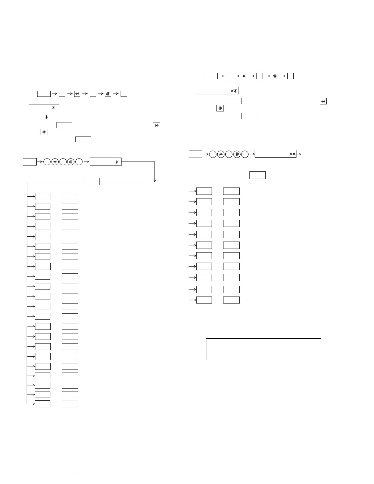
1) Soft switch mode
In this mode, the soft switch are set and the soft switch list is printed.
•OFF to ON of telephone billing function which is using the image
memory is used (Note: In the existing set, the telephone billing
code function is specified from OFF to ON when the timer system
communication (including the batch communication) is set.)
Here,thememoryisusablewhenthetelephonebillingcodefunc-
tion is on. It can be set from ON to OFF while the memory is
used. However, if setting is practically changed even once, it can
not be returned from OFF to ON.
•Switching ON/OFF of PC interface function during the use of im-
age memory.
•OFF to ON of department control function during use of image
memory.
(Note: In the existing set, the department control function is set
from OFF to ON when the timer communication (including the
batch sending) or the memory hold is set.)
•ON to OFF of continuous serial polling function when the con-
tinuous serial polling is started.
(Note: In the existing set, "ON to OFF of the continuous serial
polling function when the continuous serial polling is registered"
has been applied, but the conditions are now moderated. How-
ever, registration is impossibletotheprogram of the new continu-
ous serial polling when the continuous serial polling function is
OFF.)
•In addition, change of all soft switches during communication
7
Linked change of data (This is the same even in the optional setting.)
•When the department control function is off, the multi TTI func-
tion and telephone billing code function are turned off.
2) Print area
According to the size of the specified sheet, the effective printing area is
printed.
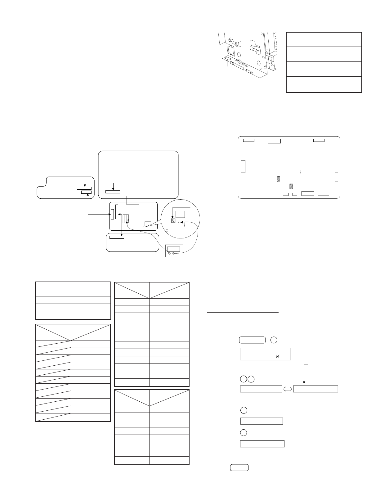
3) ROM & RAM check
The sum value of ROM, the work and the back-up RAM are checked.
The RS232C interface is also checked. If any error occurs, the buzzer
willinform it. (Refertothe following table). Finally,theresult will be printed.
This diagnosis does not check the flash memory. The flash memory is
checked with the flash memory test.
For the short and long sounds, one pattern is as follows.
Main system: 0.5 seconds ON/0.5 seconds OFF
Sub system: 1.00 second ON/0.5 seconds OFF
The execution state of checking is as follows. Moreover, the list of the
check result is output after checking is ended.
1
Switch number selection
•Press START key for setting of the next soft switch. If the soft
switch number is the final, pressing START key will exit the soft
switch mode.
•Enter two digits of a soft switch number to set the switch number.
If a switch number of unexisting soft switch is entered, key error
buzzer sounds to reject the input.
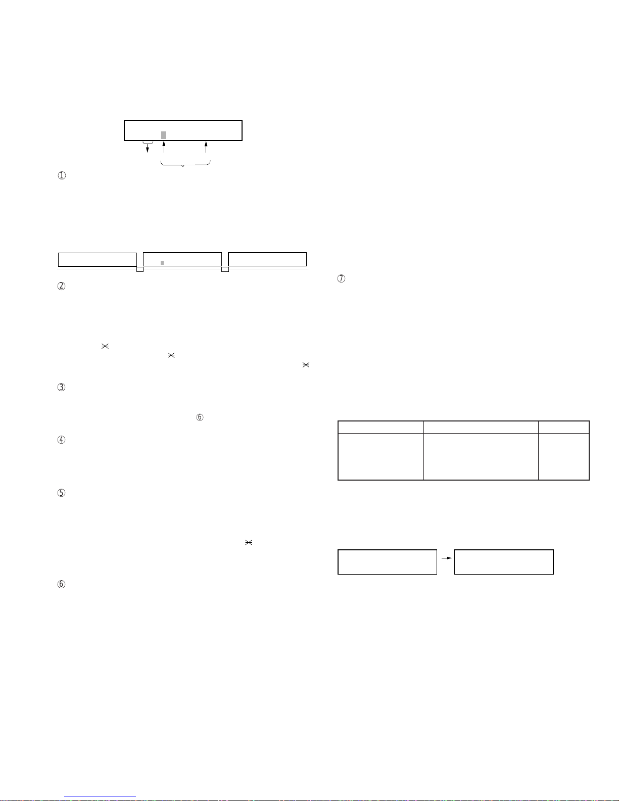
2
Data number selection
The cursor position shows the data to be set.
Pressing#keymovesthecursortotheright.If,however, the cursor is
on data number 8, pressing # key shifts the cursor to data number 1
of the next switch number. If the switch number is the final, pressing
# key will exit the soft switch mode.
Pressing key moves the cursor to the left. If, however, the cursor is
on data number 1, pressing key shifts the cursor to data number 1
of the former switch number. If the switch number is 1, pressing
key will not move the cursor and the error buzzer will sound.
3
Data setting method
Press the FUNCTION key, and the data at the position of the cursor
will be reversed to 0 when it is 1, or to 1 when it is 0. (If the soft switch
can be changed at the bit (Refer to
6
.), the error buzzer will sound
with the process not received.)
4
Outputting method of soft switch list
In the soft switch mode, press the REPORT key, and the soft switch
list will be output.
If the recording paper runs out or is clogged, the key error buzzer will
sound with the process not received.
5
Storage of data
In the following case, the data of the soft switches set will be stored.
•It is shifted to set the next soft switch by pressing the START
switch.
•It is shifted to set the next soft switch with the [#] key.
•It is shifted to set the last soft switch with the [ ] key.
•It is shifted to set another soft switch by inputting two digits as the
switch number. (When 2 digits are completely input.)
•Output of the soft switch list is started.
6
Inhibition of data change
(This is also applicable for the optional setting.)
In the following case, it is inhibited to change the data with the key
error buzzer.
•Switching ON/OFF of ECM during the use of image memory.
•Switching OFF to ON of the print hold function when the print
hold pass code has not yet been registered.
•Clearing the print hold pass code when print hold function is ON.
•Switching ON/OFF of the print hold function during the use of
memory such as in the case of substitute receiving.
S O F T S W I T C H M O D E
S W 0 1 = 0 0 0 0 0 0 0 0
Soft switch mode screen
Switch
No. 1
2
3
4
5
6
7 :DATA No.
8
Data
S O F T S W I T C H M O D E
S W 0 1 = 0 0 0 0 0 0 0 0
E N T E R L A S T D I G I T
S W 1
S O F T S W I T C H M O D E
S W 1 6 = 0 0 0 1 0 1 1 0
1 6
Number of buzzer sounds Device checked Remarks
1 time <Short sound> ROM Main
2 times <Short sounds> Integrated ROM Main
3 times <Short sounds> SRAM Main
4 times <Short sounds> DRAM Main
ROM CPU SRM DRM
• • • •
ROM CPU SRM DRM
P=PASS E=ERROR
P P P E
ROM/RAM
check list
output
Display during check Display after check