Sharp UX-P115 User manual

SERVICE MANUAL
MODEL SELECTION CODE DESTINATION
UX-P115 U U.S.A.
UX-P115U
No. 00ZUXP115USME
FACSIMILE
UX-P115
MODEL
SHARP CORPORATION
CONTENTS
Parts marked with " " are important for maintaining the safety of the set. Be sure to replace these parts with specified ones for
maintaining the safety and performance of the set.
This document has been published to be used
for after sales service only.
The contents are subject to change without notice.
CHAPTER 1. GENERAL DESCRIPTION
[1] Specifications ................................................. 1-1
[2] Operation panel.............................................. 1-2
[3] Transmittable documents ............................... 1-3
[4] Installation ...................................................... 1-4
[5] Quick setup guide .......................................... 1-8
[6] Quick reference guide .................................... 1-9
[7] Option imaging film specifications.................. 1-9
CHAPTER 2. ADJUSTMENTS
[1] Adjustments ................................................... 2-1
[2] Diagnostics and service soft switch ............... 2-2
[3] Troubleshooting ........................................... 2-20
[4] Error code table............................................ 2-21
CHAPTER 3. MECHANISM BLOCKS
[1] General description ........................................ 3-1
[2] Disassembly and assembly procedures......... 3-3
CHAPTER 4. DIADRAMS
[1] Block diagram ................................................ 4-1
[2] Wiring diagram ............................................... 4-2
[3] Point-to-point diagram.................................... 4-3
CHAPTER 5. CIRCUIT DESCRIPTION
[1] Circuit description ..........................................5-1
[2] Circuit description of control PWB ................5-2
[3] Circuit description of TEL/LIU PWB...............5-9
[4] Circuit description of power supply PWB......5-12
[5] Circuit description of CIS unit ......................5-12
CHAPTER 6. CIRCUIT SCHEMATICS AND PARTS
LAYOUT
[1] Control PWB circuit .......................................6-1
[2] TEL/LIU PWB circuit......................................6-9
[3] Power supply PWB circuit ...........................6-12
[4] Operation Panel PWB circuit .......................6-14
CHAPTER 7. OPERATION FLOWCHART
[1] Protocol .........................................................7-1
[2] Power on sequence.......................................7-2
CHAPTER 8. OTHER
[1] Service tools ..................................................8-1
[2] Changing the record paper size ....................8-4
Parts Guide

– i –
1. Employing lead-free solder
The TEL/LIU PWB and Operation Panel PWB of this model employs lead-free solder.
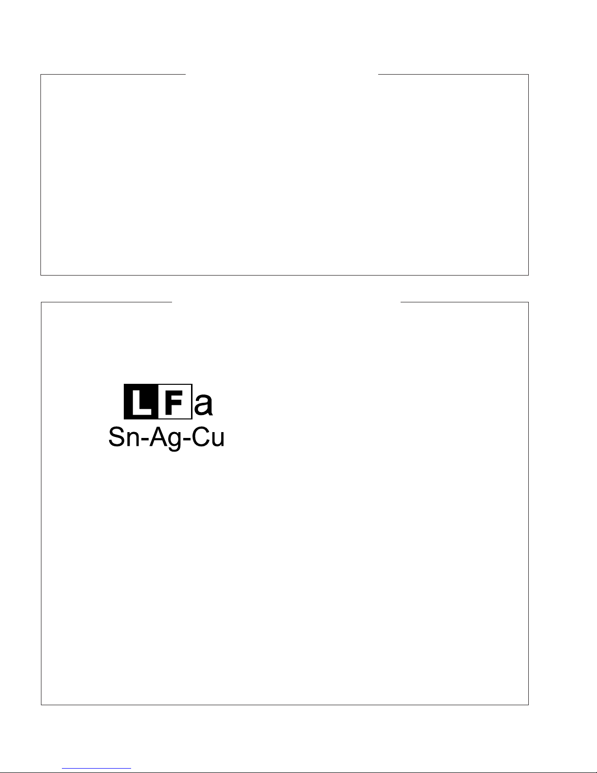
This is indicated by the "LF" symbol printed on the PWB and in the service manual.
The suffix letter indicates the alloy type of the solder.
Example:
Indicates lead-free solder of tin, silver and copper.
2. Using lead-free solder
When repairing a PWB with the "LF" symbol, only lead-free solder should be used. (Using normal tin/lead alloy solder may
result in cold soldered joints and damage to printed patterns.)
As the melting point of lead-free solder is approximately 40°C higher than tin/lead alloy solder, it is recommended that a
dedicated bit is used, and that the iron temperature is adjusted accordingly.
3. Soldering
As the melting point of lead-free solder (Sn-Ag-Cu) is higher and has poorer melting point (flow), to prevent damage to the
land of the PWB, extreme care should be taken not to leave the bit in contact with the PWB for an extended period of time.
Remove the bit as soon as a good flow is achieved.
The high content of tin in lead free solder will cause premature corrosion of the bit.
To reduce wear on the bit, reduce the temperature or turn off the iron when it is not required.
Leaving different types of solder on the bit will cause contamination of the different alloys, which will alter their
characteristics, making good soldering more difficult.
It will be necessary to clean and replace bits more often when using lead-free solder. To reduce bit wear, care should be
taken to clean the bit thoroughly after each use.
PRECAUTIONS FOR USING LEAD-FREE SOLDER
(Danish) ADVARSEL !
Lithiumbatteri-Eksplosionsfare ved fejlagtig håndtering.
Udskiftning må kun ske med batteri af samme fabrikat og type.
Levér det brugte batteri tilbage til leverandoren.
(English) Caution !
Danger of explosion if battery is incorrectly replaced.
Replace only with the same or equivalent type
recommended by the equipment manufacturer.
Discard used batteries according to manufacturer's instructions.
(Finnish) VAROITUS
Paristo voi räjähtää, jos se on virheellisesti asennettu.
Vaihda paristo ainoastaan laitevalmistajan suosittelemaan
tyyppiin. Hävitä käytetty paristo valmistajan ohjeiden mukaisesti.
(French) ATTENTION
Il y a danger d'explosion s' il y a remplacement incorrect
de la batterie. Remplacer uniquement avec une batterie du
même type ou d'un type recommandé par le constructeur.
Mettre au rébut les batteries usagées conformément aux
instructions du fabricant.
(Swedish) VARNING
Explosionsfare vid felaktigt batteribyte.
Använd samma batterityp eller en ekvivalent
typ som rekommenderas av apparattillverkaren.
Kassera använt batteri enligt fabrikantens
instruktion.
(German) Achtung
Explosionsgefahr bei Verwendung inkorrekter Batterien.
Als Ersatzbatterien dürfen nur Batterien vom gleichen Typ oder
vom Hersteller empfohlene Batterien verwendet werden.
Entsorgung der gebrauchten Batterien nur nach den vom
Hersteller angegebenen Anweisungen.
CAUTION FOR BATTERY REPLACEMENT
UX-P115U

UX-P115U
1 – 1
FAXUX-P115UService ManualService ManualMarketE
CHAPTER 1. GENERAL DESCRIPTION
[1] Specifications
Automatic dialing:
Imaging film:
Memory size*:
Modem speed:
Transmission time*:
Resolution:
Automatic document
feeder:
Recording system:
Halftone (grayscale):
Compression scheme:
Display:
Applicable telephone line:
Paper tray capacity:
30 numbers
Initial starter roll:
(included with machine): 32 ft.(10 m)
(approx. 30 letter-size pages)
Replacement roll (not included):
UX-5CR 164 ft.(50 m) (one roll yields
approx. 150 letter-size pages)
448 KB (approx. 24 average pages)
9,600 bps with automatic fallback to
lower speed
Approx. 15 seconds
Horizontal: 203 pixels/inch (8 dots/mm)
Vertical:
Standard: 98 lines/inch (3.85 lines/mm)
Fine/Halftone: 196 lines/inch
(7.7 lines/mm)
Super fine: 391 lines/inch
(15.4 lines/mm)
10 pages max. (letter/A4, 20-lb. paper)
Thermal transfer recording
64 levels
MR, MH, Sharp(H2)
16-digit LCD display
Public switched telephone network
Letter: Approx. 50 sheets (20-lb. copier
paper at room temperature; maximum
stack height should not be higher than
the line on the tray)
Legal: 5 sheets
Recommended paper weight is 20-lb.
Copy Bond
Compatibility:
Input document size:
Effective scanning width:
Effective printing width:
Contrast control:
Reception modes:
Copy function:
Telephone function:
Power requirements:
Operating temperature:
Humidity:
Power consumption:
Dimensions (without
attachments):
Weight (without attach-
ments):
ITU-T (CCITT) G3 mode
Automatic feeding:
Width: 5.8 to 8.5” (148 to 216 mm)
Length: 5.5 to 11” (140 to 279 mm)
Manual feeding:
Width: 5.8 to 8.5” (148 to 216 mm)
Length: 5.5 to 23.6” (140 to 600 mm)
8.3” (210 mm) max.
8.3” (210 mm) max.
Automatic/Dark selectable
TEL/FAX
Single / Multi (99 copies/page)
Yes
(cannot be used if power fails)
120 V AC, 60 Hz
41 - 95°F (5 - 35°C)
25 - 85 % RH
Stand-by: 3.6 W
Maximum: 100 W
Width: 12.9” (327 mm)
Depth: 7.6” (193 mm)
Height: 6.4” (163 mm)
Approx. 6.2 lbs (2.8 kg)
*Based on Sharp Standard Chart at standard resolution in Sharp spe-
cial mode, excluding time for protocol signals (i.e., ITU-T phase C
time only).
As a part of our policy of continuous improvement, SHARP reserves the right to make design and specification changes for product improvement
without prior notice. The performance specifications figures indicated are nominal values of production units. There may be some deviations from
these values in individual units.

UX-P115U
1 – 2
[2] Operation panel
1. SPEAKER key
Press this key to listen to the line and fax tones through the speaker
when faxing a document.
Note: This is not a speakerphone. You must pick up the handset to
talk with the other party.
2. RESOLUTION / RECEPTION MODE key
When a document is in the feeder, press this key to adjust the resolu-
tion for faxing or copying. At any other time, press this key to select the
reception mode (an arrow in the display will point to the currently
selected reception mode).
3. FLASH key
This key is used for Call Waiting and other special services that
require subscription from your phone company. Your phone company
will provide you with details on how to use the key.
4. POLL key
Press this key after dialing another fax machine to receive a document
(previously loaded in the other machine's feeder) without assistance
from the operator of the other machine.
5. HOLD key
Press this key to put the other party on hold during a phone conversa-
tion.
6. Display
This displays messages and prompts to help you operate the machine.
7. UP and DOWN arrow keys
Enlarge/Reduce setting: When marking a copy of a document, press
these keys to select an enlarge/reduce setting.
Volume setting: When a document is not in the feeder, press these
keys to change the handset volume when the handset is lifted, the
speaker volume when the SPEAKER key has been pressed, or the
ringer volume at any other time.
FUNCTION key setting: Press these keys after pressing the FUNC-
TION key to scroll through the FUNCTION MODE settings.
8. Number keys
Use these keys to dial numbers, and enter numbers and letters when
storing auto-dial numbers.
9. Panel release
Press this release to open the operation panel.
10. STOP key
Press this key to cancel operations before they are completed.
11. COPY/HELP key
When a document is in the feeder, press this key to make a copy of a
document. At any other time, press this key to print out the Help List, a
quick reference guide to the operation of your fax machine.
12. START/MEMORY key
Press this key after dialing to begin fax transmission. Press this key
before dialing to send a fax through memory.
13. SPEED key
Press this key to dial a fax or voice number using an abbreviated 2-
digit Speed Dial number.
14. Left and right arrow keys
Auto-dial numbers: When sending a fax or making a phone call,
press these keys to scroll through your auto-dial numbers, the
"REVIEW CALLS" list (only available if you have Caller ID), and the
last number dialed (redial).
FUNCTION key settings: Press the right arrow key after scrolling with
the up and down arrow keys to select a FUNCTION key setting.
15. FUNCTION key
Press this key to followed by the arrow keys select special functions
and setting.
14
13 15
14 5
23
12
10 11
JKL
ABC
1
DEF
WXYZ
9
GHI
45
MNO
6
PQRS
7
TUV
8
0
2 3
RESOLUTION/
RECEPTION MODE
FUNCTION
STOP
SPEED
COPY/HELP
START/MEMORY
ZA
TEL FAX
SPEAKER
FLASH
REDIAL
POLL
HOLD
6 7 8 9

UX-P115U
1 – 3
[3] Transmittable documents
1. Document Sizes
Use document carrier sheet for smaller documents.
• With special sizes, only one sheet can be fed into the machine at a
time. Insert next page into feeder as current page is being scanned.
2. Paper Thickness & Weight
3. Document Types
• Normal paper
Documents handwritten in pencil (No. 2 lead or softer), fountain
pen, ball-point pen, or felt-tipped pen can be transmitted.
Documents of normal contrast duplicated by a copying machine
can also be transmitted.
• Diazo copy (blue print)
• Diazo copy documents of a normal contrast may be transmitted.
• Carbon copy
A carbon copy may be transmitted if its contrast is normal.
4. Cautions on Transmitting Documents
• Documents written in yellow, greenish yellow, or light blue ink can-
not be transmitted.
• Ink, glue, and correcting fluid on documents must be dry before the
documents can be transmitted.
• All clips, staples and pins must be removed from documents before
transmission.
• Patched (taped) documents should be copied first on a copier and
then the copies used for transmission.
• All documents should be fanned before insertion into the feeder to
prevent possible double feeds.
5. Automatic Document Feeder Capacity
Number of pages that can be placed into the feeder at anytime is as
follows:
Normal size: max. ADF 10 pages
Special size: single sheet only (manual feed)
NOTE: •When you need to send or copy more pages than the feeder
limit, place additional pages in feeder when last page in feeder
is being scanned.
•Place additional pages carefully and gently in feeder.
If force is used, double-feeding or a document jam may result.
6. Readable Width & Length
The readable width and length of a document are slightly smaller than
the actual document size.
Note that characters or graphics outside the effective document scan-
ning range will not be read.
• Readable width
8.3” (210mm), max
• Readable length
This is the length of the document sent minus 0.2” (5mm) from the
top and bottom edges.
Normal size width 5.8 to 8.5” (148 - 216 mm)
length 5.5 to 11” (140 - 279 mm)
10 sheets 1 sheet (Manual)
Paper weight 70 kg
80 g/m2
70 kg ~ 135 kg
52 g/m2~ 157g/m2
Paper thickness (ref.) 0.1 mm 0.1 mm ~ 0.18mm
Paper size LGL (216 mm x 355.6 mm)
A4 (210 mm x 297 mm)
LTR (216 mm x 279 mm)
Feeder capacity A4/LTR: 10 sheets
LGL : 1 sheet
(Min.)
(Max.)
Letter
size
(Max.)
140mm
279mm
600mm
148mm 216mm
[Normal size]
216mm
[Special size]
Readable widt
h
0.2" (5mm)
0.2" (5mm)
Readable length

UX-P115U
1 – 4
[4] Installation
1. Site selection
Take the following points into consideration when selecting a site for
this model.
ENVIRONMENT
• The machine must be installed on a level surface.
• Keep the machine away from air conditioners, heaters, direct sun-
light, and dust.
• Provide easy access to the front, back, and sides of the machine.
In particular, keep the area in front of the machine clear, or the orig-
inal document may jam as it comes out after scanning.
• The temperature should be between 41 - 95°F (5 - 35°C).
• The humidity should be between 25% and 85% (without conden-
sation).
ELECTRICITY
AC 120V, 60Hz, grounded (3-prong) AC outlet is required.
Caution!
• Connection to a power source other than that specified will cause
damage to the equipment and is not covered under the warranty.
• If your area experiences a high incidence of lightning or power
surges, we recommend that you install a surge protector for the
power and telephone lines. Surge protectors can be purchased at
most telephone specialty stores.
If the machine is moved from a cold to a warm place...
Condensation may form on the reading glass if machine is moved from
a cold to a warm place, this will prevent proper scanning of documents
for transmission. Turn on the power and wait approximately 2 hours
before using machine.
TELEPHONE JACK
A standard RJ11C single-line wall telephone jack must be located near
the machine. This is the telephone jack commonly used in most
homes and offices.
• Plugging the fax machine into a jack which is not RJ11C single-line
wall telephone jack may result in damage to the machine or your
telephone system. If you do not know what kind of jack you have, or
need to have one installed, contact the telephone company.
2. Loading the imaging film
Your fax uses a roll of imaging film to create printed text and images.
The print head in the fax applies heat to the imaging film to transfer ink
to the paper. Follow the steps below to load or replace the film.
• The initial starter roll of imaging film included with your fax can print
about 30 letter-size pages
• When replacing the film, use a roll of Sharp UX-5CR imaging film.
One roll can print about 150 letter-size pages.
1) Remove the paper from the paper tray and open the operation
panel (press ).
2) Remove the used film and empty spool.
3) Remove the two green gears from the spools.
DO NOT DISCARD THE TWO GREEN GEARS!
4) Remove the new roll of imaging film from its packaging.
• Cut the band that holds rolls together.
5) Insert the green gears.
Make sure the gears fit into the slots in the ends of the rolls.
Use only Sharp Genuine
Supplies with this logo:
1
1
2
If you are loading the imaging film for the first
time, go to Step 4.
1 slot
2 slots

UX-P115U
1 – 5
6) Insert the film into the print compartment.
7) Rotate the front gear as shown until the film is taut.
8) Close the operation panel (press down on both sides to make sure
it clicks into place).
3. Connections
1) Connect the handset as shown and place it on the handset rest.
• The ends of the handset cord are identical, so they will go into
either jack.
• Make sure the handset cord goes into the jack marked with a
handset symbol on the side of the machine.
• Use the handset to make ordinary phone calls, or to transmit
and receive faxes manually.
2) Plug the power cord into a 120 V, 60 Hz, grounded AC (3-prong)
outlet.
Caution!
Do not plug the power cord into any other kind of outlet. This will
damage the machine and is not covered under the warranty.
• The machine does not have a power on/off switch, so the power
is turned on and off by simply plugging in or unplugging the
power cord.
3) Insert one end of the line cord into the jack on the back of the
machine marked TEL. LINE. Insert the other end into a standard
(RJ11C) single-line wall telephone jack.
Setting the dial mode: The fax machine is set for tone dialing. If you
are on a pulse dial line, you must set the fax machine for pulse dial-
ing. Press the keys on the operation panel as follows:
4) Attach the paper tray and paper tray extension.
Note: The paper tray extension has a top side and a bottom side. If
you cannot insert the tabs into the holes, turn the support over.
Fit ends of rolls
onto hubs
Thick roll
to rear
TEL.
LINE
1. Press once and once.
2. Press once and twice.
3. Press once.
4. Select the dial mode:
TONE: PULSE:
5. Press to exit.
12
OPTION SETTING
Display:
DIAL MODE
1=TONE, 2=PULSE
DISTINCTIVE
The display briefly shows
your selection, then:
FUNCTION
STOP
Insert
horizontally
and rotate up.
Click!
Attach the paper tray. Attach the paper tray extension.

UX-P115U
1 – 6
4. Loading printing paper
You can load letter or legal size paper in the paper tray. Recom-
mended paper weight is 20-lb. Copy Bond. The maximum number of
sheets is as follows:
Letter size: Approx. 50 sheets (20-lb. copier paper at room tempera-
ture; maximum stack height should not be higher than the line on the
tray)
Legal size: 5 sheets
1) Fan the paper, and then tap the edge against a flat surface to even
the stack. Make sure the stack edges are even.
2) Insert the stack of paper into the tray, PRINT SIDE DOWN.
• If paper remains in the tray, take it out and combine it into a sin-
gle stack with the new paper.
• Be sure to load the paper so that printing takes place on the
print side of the paper. Printing on the reverse side may result
in poor print quality.
•GENTLY LOAD PAPER INTO THE PAPER TRAY.
•DO NOT FORCE IT DOWN INTO THE FEED SLOT.
Note: Do not use paper that has already been printed on, or
paper that is curled.
3) Setting the paper size.
The fax has been set at the factory to scale received faxes to letter
size paper. If you loaded legal paper, you must change the paper
size setting to LEGAL.
4) Print contrast setting.
You fax has been set at the factory to print at normal contrast. If
desired, you can change the print contrast setting to LIGHT.
The stack
should not
be higher
than this line.
Note: If at any time the display shows
the alternating messages at right, check
the printing paper. If the tray is empty,
add paper. If these is paper in the tray,
take it out and then reinsert it.
When you are finished, press .
START/MEMORY
ADD PAPER &
PRESS START KEY
↑
↑
1. Press once and once.
2. Press once and twice.
3. Press once.
4. Select the paper size:
LETTER: LEGAL:
5. Press to return to the date and time display.
12
OPTION SETTING
Display:
PAPER SIZE SET
1=LETTER, 2=LEGAL
COPY CUT-OFF
The display briefly shows
your selection, then:
FUNCTION
STOP
1. Press once and once.
2. Press once and 3 times.
3. Press once.
4. Select the print contrast:
NORMAL: LIGHT:
5. Press to return to the date and time display.
12
OPTION SETTING
Display:
PRINT CONTRAST
1: NORMAL
PAPER SIZE SET
The display briefly shows
your selection, then:
FUNCTION
STOP

UX-P115U
1 – 7
5. Clearing a jammed document
If the original document doesn’t feed properly during transmission or
copying, or DOCUMENT JAMMED appears in the display, first try
pressing the START/MEMORY key. If the document doesn’t feed out,
remove it as explained below.
Important:
Do not try to remove a jammed document without releasing it as
explained below. This may damage the feeder mechanism.
1) Press and slowly open the operation panel until it is half open.
2) Flip up the green levers on each side of the white roller.
3) Gently and remove the document.
• Be careful not to tear the document.
4) Flip down the green levers on each side of the white roller. Rotate
the front gear until the film is taut, and then close the operation
panel (press down on both sides to make sure it clicks into place).
6. Clearing jammed printing paper
1) Open the operation panel (press )
2) Gently pull the jammed paper out of the machine, making sure no
torn pieces of paper remain in the print compartment or rollers.
3) Rotate the front gear until the film is taut, and then close the opera-
tion panel (press down on both sides to make sure it clicks into
place).
1
1
2
1
1
2

UX-P115U
1 – 8
[5] Quick setup guide
5
4. Insert the film into the print compartment. 5. Rotate the front spool as shown
until the film is taut.
6. Close the operation panel (press
down on both sides to make sure it
clicks into place).
Fit ends of
rolls onto hubs
6
Load paper.
Note: If you loaded legal paper, see of the operation manual to change the paper size
setting to LEGAL.
7
Select the reception mode for incoming faxes and
voice calls:
FAX mode: The machine automatically answers all
calls and begins fax reception.
TEL mode: Lift the handset when the machine rings.
Press to begin fax reception.
START/MEMORY
FAX
TEL
JAN-01 10:30
FAX
TEL
JAN-01 10:30
The arrow points
to the selected
reception mode.
RESOLUTION/
RECEPTION MODE
Insert the
paper print
side down.
The stack
should not be
higher than this
line
• GENTLY LOAD PAPER INTO THE PAPER TRAY.
• DO NOT FORCE IT DOWN INTO THE FEED SLOT.
13
Plug the power cord
into a 120 V grounded
outlet.
Connect the telephone
linecordtotheTEL.
LINE jack and a wall
telephone jack.
Attach the paper tray
and document support.
Note: To enter your name and fax number and set the date and time so that they
appear at the top of each fax you send, see page Chapter 1 of your operation manual.
2
Connect the handset
and place it on the
handset rest.
TEL.LINE
Click!
4
Note: If the
support does
not go in,
turn it over.
Load the imaging film.
1. Open the operation panel (press ). 3. Insert the green gears.
IMPORTANT: Do NOT discard the
green gears. They are not included
with replacement imaging film.
2. Remove the imaging film from its packaging.
Cut the band that holds the rolls together.
1 slot
2 slots
Make sure
the gears fit
into the slots
in the ends of
the rolls.
1
2
1

UX-P115U
1 – 9
[6] Quick reference guide
1. Sending Faxes
Place your document (up to 10 pages) face down in the document
feeder.
1.1. Normal Dialing
1. Lift the handset or press .
2. Dial the fax number.
3. Wait for the reception tone (if a person answers, ask them to press
their Start key).
4. Press .
1.2. Speed Dialing
1. Press .
2. Enter the 2-digit Speed Dial number.
3. Press .
1.3. Search Dialing
1. Press or until the name of the other party appears in
the display (if no name was stored, the number will appear).
2. Press .
2. Receiving Faxes
Press the until the arrow in the display points to the
desired reception mode.
FAX mode: The fax machine automatically answers and receives the
incoming document.
TEL mode: Answer all calls (even faxes) by picking up the handset. To
begin fax reception, press .
3. Storing Auto Dial Numbers
1. Press once and once.
2. Enter a 2-digit Speed Dial number (01 to 30).
3. Enter the fax number and press .
4. Enter a name by pressing number keys. (To enter two letters in
succession that require the same key, press after entering
the first letter.)
5. Press and then .
[7] Option imaging film specifications
1. Structure
This article is composed of polyester film coated with heat-resistant
layer, matt layer and hot melt ink layer, leader film and paper core. Ink
film specification is "DNP standard ink film HC".
2. Details of compositions
2.1. Base film
2.2. Heat resistant layer
2.3. Matt layer
2.4. Hot melt ink layer
SPEAKER
START/MEMORY
SPEED
START/MEMORY
START/MEMORY
RESOLUTION/
RECEPTION MODE
RESOLUTION/
RECEPTION MODE
FAX
TEL
JAN-01 10:30
FAX
TEL
JAN-01 10:30
START/MEMORY
Heading Requirements Measuring method
Material Polyethylene-
terephthalate
–
Heading Requirements Measuring method
Grade HR Mixer P-5 –
Heading Requirements Measuring method
Grade ML Sumi –
Heading Requirements Measuring method
Grade #507W –
FUNCTION
START/MEMORY
A=
B=
C=
D=
E=
F=
G=
H=
I=
J=
K=
L=
M=
N=
O=
P=
Q=
R=
S=
T=
U=
V=
W=
X=
Y=
Z=
SPACE =
START/MEMORY
STOP
1
2
3
4
1
2
3
4
Heat Resistant Layer
Base Film
Matt Layer
Hot melt Ink Layer

UX-P115U
2 – 1
FAXUX-P115UService ManualService ManualMarketE
CHAPTER 2. ADJUSTMENTS
[1] Adjustments
1. General
Since the following adjustments and settings are provided for this
model, make adjustments and/or setup as necessary.
2. Adjustments of output voltage (FACTORY ONLY)
1. Install the power supply unit in the machine.
2. Set the recording paper and document.
3. When the document is loaded, power is supplied to the output
lines. Confirm that outputs are within the limits below.
2.1. Output voltage settings
3. IC protectors replacement
ICPs (IC Protectors) are installed to protect the motor driver circuit.
ICPs protect various ICs and electronic circuits from an overcurrent
condition.
The location of ICPs are shown below:
1) FU100 (KAB3202) is installed in order to protect IC's from an
overcurrent generated in the motor drive circuit. If FU100 is open,
replace it with a new one.
4. Settings
4.1. Dial mode selector
DIAL mode (Soft Switch No. SW-B4 DATA No. 3)
5. Volume adjustments
You can adjust the volume of the speaker, handset, and ringer using
the UP and DOWN keys.
5.1. Speaker
1. Press the SPEAKER key.
2. Press the UP or DOWN key until the display shows the desired vol-
ume level.
5.2. Handset
1. When talking through the handset, press UP or DOWN key until the
display shows the desired volume level.
5.3. Ringer
1. Press the UP or DOWN key. (Make sure SPEAKER key has not
been pressed, the handset is not lifted, and a document is not
loaded in the feeder.)
2. If you selected RINGER OFF: OK?, press START/ MEMORY key.
TEL/LIU PWB
POWER
SUPPLY
PWB
CONTROL
PWB
CNMT
CNLIUA
CNLIUA
CNPS
CNPW
CNPN CNCIS
CNSP
CNCSW
CNTH
CNPRG
Output Voltage limits
Vreg(+5V) 4.25V ~ 5.75V
+24V 23.3V ~ 24.7V
1 +24V
2 +24V
3MG
4MG
5DG
6 Vreg(+5V)
Connector
No. CNPW
Pin No.
61
CONTROL PWB
(BOTTOM SIDE)
CNLIUA
FU100
CNPW
(step 1) Select "OPTION SETTING".
KEY : FUNCTION
DISPLAY: OPTION SETTING NUMBER OF RING
(step 2) Select "DIAL MODE".
KEY: Push until DIAL MODE is
indicated because the number of
's changes by the model.
DISPLAY: DIAL MODE 1=TONE, 2=PULSE
(step 3) Select, using "1" or "2".
KEY: 1
DISPLAY: TONE SELECTED
KEY: 2
DISPLAY: PULSE SELECTED
(step 4) End, using the "STOP" key.
KEY:
STOP
Display:
SPEAKER: HIGH
SPEAKER: MIDDLE
SPEAKER: LOW
↔
↔
• Press SPEAKER key again to
turn off the speaker.
Display:
RECEIVER: HIGH
RECEIVER: MIDDLE
RECEIVER: LOW
↔
↔
•Note:The volume reverts to
MIDDLE each time you
replace the handset.
Display:
RINGER: HIGH
RINGER: MIDDLE
RINGER: LOW
RINGER OFF: OK?
↔
↔
↔
• The ringer will ring once at the
selected level, then the date
and time will reappear in the
display.

UX-P115U
2 – 2
[2] Diagnostics and service soft switch
1. Operating procedure
1.1. Entering the diagnostic mode
2. Diagnostic items
ITEM No. Contents Function
1 SOFT SWITCH MODE Soft switches are displayed and changed. List can be output.
2 ROM & RAM CHECK ROM is sum-checked, and RAM is matched. Result list is output.
3 AGING MODE 10 sheets of check patterns are output every 5 minutes per sheet.
4 PANEL KEY TEST Panel keys are tested. Result list is output.
5 CHECK PATTERN Check pattern is output.
6 SIGNAL SEND MODE Various signals of FAX communication are output.
7 MEMORY CLEAR Back-up memory is cleared, and is set at delivery.
8 SHADING MODE Shading compensation is performed in this mode.
9 ALL BLACK PRINT To check the print head, whole dots are printed over the interval of 2 m.
10 AUTO FEEDER MODE Insertion and discharge of document are tested.
11 ENTRY DATA SEND Registered content is sent.
12 ENTRY DATA RECEIVE Registered content is received, and its list is output.
Press FUNC →9→→ 8→#→7 , and the following display will appear.
ROM Ver. TC89 After 2 sec: DIAG MODE
TC89
Then press the START key. Select the desired item with the key or the # key or select with the rapid key. Enter the mode with the START key.
(Diag· specifications)
If the diag mode cannot be set, repeat the diag mode operation, per-
forming the following operation.
After the power is turned on and "WAIT A MOMENT" is indicated, press
the STOP key.
In relation with the process response (request from Production
Engineering) "WAIT A MOMENT" clock indication may appear depending
on STOP key timing. If the STOP key is held down, "MEMORY CLEAR?"
appears.
FUNC DIAG MODE
9 8 7
STARTSoft switch mode
START
ROM & RAM check
START
Aging mode
START
Panel key test
START
Check pattern
START
Signal send mode
Shading mode
START
START
All black mode
START Auto feeder mode
START
Entry data send
Entry data receive
START
START
START
KEY
STOP
KEY
+
"Power ON"
Memory clear
(Work + Backup)
Memory clear
START
TC89

UX-P115U
2 – 3
3. Diagnostic items description
3.1. Soft switch mode
Used to change the soft switch settings.
The soft switch which is stored internally is set by using the keys.
The available soft switches are SW-A1 to SW-O6.
The content of soft switches is shown in page 2-5 to 2-18.
The contents are set to factory default settings.
3.2. ROM & RAM check
ROM executes the sum check, and RAM executes the matching test.
The result will be notified with the number of short sounds of the
buzzer as well as by printing the ROM & RAM check list.
Number of short sounds of buzzer:
0 →No error
1 →ROM error
2 →RAM error (4 Kbyte SRAM or 512 Kbyte DRAM)
3.3. Aging mode
If any document is present, copying will be executed sheet by sheet. If
no document is present, the check pattern will be printed sheet by
sheet. This operation will be executed at a rate of one sheet per 5 min-
utes, and will be ended at a total of 10 sheets.
3.4. Panel key test
This mode is used to check whether each key operates properly.
Press the key on the operation panel, and the key will be displayed on
the display. Therefore, press all keys. At this time, finally press the
STOP key.
When the STOP key is pressed, the keys which are not judged as
"pressed" will be printed on the result list.
• LED part of the contact image sensor (CIS) is kept on during the
term from when “START” of the panel test mode to end with the
STOP key.
3.5. Check pattern
This mode is used to check the state of the printing head. It is ended
with the following pattern printed on one printing sheet.
3.6. Signal send mode
This mode is used to send various signals to the circuit during FAX
communication. Every push of START key sends a signal in the follow-
ing sequence. Moreover, the signal sound is also output to the speaker
when the line monitor of the soft switch is on.
[1] No signals
[2] 9600BPS (V.29)
[3] 7200BPS (V.29)
[4] 4800BPS (V27ter)
[5] 2400BPS (V27ter)
[6] 300BPS (FLAG)
[7] 2100Hz (CED)
[8] 1100Hz (CNG)
3.7. Memory clear
This mode is used to clear the backup memory and reset to the default
settings.
3.8. Shading mode
The mode is used for the shading compensation. For reading, set up
the special original paper.
The compensation memorizes the reference data of white and black
for reading.
Moreover, the memorized data is not erased even if memory clear
mode is executed.
3.9. All black print
This mode is used to check the state of the printing head and to inten-
tionally overheat it. Whole dots are printed over the interval of 2 m. If it
is overheated or the printing sheet is jammed, press STOP key for the
end.
3.10. Auto feeder mode
In this mode, a document is inserted and discharged to check the auto
feed function.
After this mode is started, set a document, and the document feed will
be automatically tested.
3.11. Entry data send
This mode is used to send the registered data to another machine and
make the other machine copy the registered content.
Before sending in this mode, it is necessary to set the other machine
at the entry data receive mode.
The following, information will be sent to the remote machine:
1. Telephone list data
2. Sender register data
3. Optional setting content
4. Soft switch content
5. Junk fax number list
6. Recording setting list data
1
BBBBBBBBBBBBBBBBBBBBBBBBBBBBBBBBBBBBBBBBB
2
3
4
1DOT
2DOTS
3DOTS
4DOTS

UX-P115U
2 – 4
3.12. Entry data receive
In this mode, the registered data sent from the other machine is receiv-
ed and the received data is registered in the machine. When this mode
is used for receiving, the other machine must be in the entry data send
mode.
After receiving is completed, the following lists are printed.
1.Telephone list data
2.Sender register data (*)
3.Optional setting list (*)
4.Soft switch content
5.Junk fax number list (*)
6.Recording setting list data (*)
(*): Refer to SETUP LIST
4. How to make soft switch setting
To enter the soft switch mode, press the following key entries in sequence.
Press FUNCTION 9 8 7 STARTSTART
Press FUNCTION key.
Press key.
Press key.
Bit1 - 8 are set.
Soft SW-A2 - SW-O6 are set.
S F T SW-A1 = 10000000
S F T SW-A2 = 00000000
S F T SW-O6 = 00000000
Press key during setting.
To finish the settings halfway between
SW-A1 and SW-O6, press the STOP
key. In this case, the setting being done
to the SW No. on display will be nullified
while settings done to the preceding
SW No. remain in effect.
The soft switch mode is terminated.
S F T SW-A1 = 00000000
START
DATA No. 1 2 3 4 5 6 7 8
When the COPY key is pressed, the
contents of soft switches are printed.

UX-P115U
2 – 5
5. Soft switch description
5.1. Soft switch
SW
NO.
DATA
NO. ITEM Switch setting and function Initial setting Remarks
10U
SW
l
A1
1 Protect from echo No Yes 0
2 Forced 4800 BPS reception Yes No 0
3 Footer print Yes No 0
4 Length limitation of copy/send/
receive
No limit Copy/send: 60 cm
Receive: 1 m
0
5 CSI transmission No transmitted Transmitted 0
6 DIS receive acknowledgement dur-
ing G3
Twice NSF: Once
DIS: Twice
0
7 Non-modulated carrier for V29 trans-
mission modem
Yes N o 0
8 EOL detect timer 25s 13s 0
SW
l
A2
1
2
3
4
Modem speed V.29 V.27 ter
0
0
0
1
9600bps 7200bps 4800bps 2400bps
No.10000
No.20000
No.30110
No.41100
5 Sender’s No Yes 0
6 H2 mode No Yes 0
7 Communication error treatment in
TRN sending mode (reception)
No communication error Communication error 0
8 CNG transmission No Yes 0
SW
l
A3
1
2
CED tone signal interval 1000ms 750ms 500ms 75ms
0
0
No.11100
No.21010
3 MR coding No Yes 0
4Reserved 0
5Reserved 0
6Reserved 0
7Reserved 0
8Reserved 0
SW
l
A4
1
2
3
4
5
Signal transmission level 0
1
0
0
0
6Protocol monitor (Error print) Printed at communication
error Not printed 0
7 Protocol monitor Yes No 0
8 Line monitor Yes No 0
SW
l
A5
1
2
Digital line equalization setting
(Reception)
7.2km 0km
1
1
No. 1 1 0
No. 2 1 0
3
4
Digital line equalization setting
(Transmission)
7.2km 0km
0
0
No. 3 1 0
No. 4 1 0
5
6
Digital cable equalizer setting
(Reception for Caller ID)
7.2km 0km
0
0
No. 5 1 0
No. 6 1 0
7 Error criterion 10 ~ 20 % 5 ~ 10 % 0
8 Anti junk fax check Yes No 1
Binary input
No.=168421
12345
01000

UX-P115U
2 – 6
SW
NO.
DATA
NO. ITEM Switch setting and function Initial setting Remarks
10U
SW
l
A6
1Reserved 0
2EndBuzzer Yes No 1
3 Disconnect the line when DIS is
received in RX mode
No Yes 1
4 Equalizer freeze control (MODEM) On Off 0
5 Equalizer freeze control 7200 BPS
only
No Yes 0
6 CNG transmission in manual TX
mode
Yes N o 1
7 Initial compression scheme for sharp
fax in TX mode
MR mode H2 mode 0
8 Modem speed automatic fallback
when RX level is under -40dBm
Yes N o 0
SW
l
B1
1
2
3
4
Recall interval 0
1
0
1
5
6
7
8
Recall times 0
0
1
1
SW
l
B2
1 Dial pausing (sec./pause) 4 sec. 2 sec. 0
2 Dial tone detection (before auto dial) No Yes 1
3Reserved 0
4 Busy tone detection (after auto dial) No Yes 0
5
6
Waiting time after dialing 45 sec. 55 sec. 90 sec. 140 sec.
0
0
No.50011
No.60011
7Reserved 0
8Reserved 0
SW
l
B3
1Reserved 0
2Reserved 0
3Reserved 0
4Reserved 0
5Reserved 0
6
7
Auto dial mode delay timer of before
line connect
0 sec. 1.5 sec. 3.0 sec. 4.5 sec.
0
0
No.60011
No.70101
8 Hold key Enable Disable 1
SW
l
B4
1
2
Auto dial mode delay timer of after
line connect
1.7 sec. 3.0 sec. 3.6 sec. 4.0 sec.
0
0
No.10011
No.20101
3 Dial mode Tone Pulse 1 OPTION
4Pulse→Tone change function by
key
Enable Disable 1
5 Dial pulse make/break ratio (%) 40/60 33/67 1
6Reserved 0
7Reserved 0
8 Recalling fixed only one time when
dialing was unsuccessful without
detecting busy tone signal
Yes N o 1
Binary input
No. = 8 4 2 1
12 3 4
01 0 1
Binary input
No.=8421
5678
0011

UX-P115U
2 – 7
SW
NO.
DATA
NO. ITEM Switch setting and function Initial setting Remarks
10U
SW
l
B5
1
2
3
4
5
DTMF signal transmission level
(Low)
0
1
0
0
1
6Reserved 0
7Reserved 0
8Reserved 0
SW
l
B6
1
2
3
4
5
DTMF signal transmission level
(High)
0
0
1
0
1
6Reserved 0
7Reserved 0
8Reserved 0
SW
l
C1
1
2
Reading slice (Binary) Factory
setting
Light Dark Darker
in dark
0
0
No.10101
No.20011
3
4
Reading slice (Half tone) Factory
setting
Light Dark Darker
in dark
0
0
No.30101
No.40011
5 Line density selection Fine Standard 0
6Reserved 0
7 MTF correction in half tone mode No Yes 0
8Reserved 0
SW
l
D1
1
2
3
4
Number of rings for auto receive 0
1
0
0
OPTION
5 Automatic switching manual to auto
receive mode
Reception after 5 rings No reception 0
6Reserved 0
7
8
Cl detect frequency As PTT 11.5Hz 13.0Hz 20.0Hz
0
0
No.70011
No.80101
SW
l
D2
1
2
3
Distinctive ringing setting (PATTERN
4 and 5 are for CANADA only)
No. 1 No. 2 No. 3 0
0
0
OPTION
OFF 0 0 0
STANDARD 0 0 1
PATTERN1 0 1 0
PATTERN2 0 1 1
PATTERN3 1 0 0
PATTERN4 1 0 1
PATTERN5 1 1 0
4Reserved 0
5 Caller ID function Yes No 0 OPTION
6 Caller ID detect during CI off All times Only first 0
7Reserved 0
8Reserved 0
No. = 16 8 4 2 1
1 2345
01001
Binary input
Binary input
No. = 16 8 4 2 1
12345
00101
Binary input
No.=8421
1234
0100

UX-P115U
2 – 8
SW
NO.
DATA
NO. ITEM Switch setting and function Initial setting Remarks
10U
SW
l
D3
1
2
3
4
5
Cl off detection timer (0-1550ms set-
ting by 50ms step)
0
1
1
1
0
6Reserved 0
7Reserved 0
8Reserved 0
SW
l
E1
1Reserved 0
2Reserved 0
3Reserved 0
4Reserved 0
5Reserved 0
6Reserved 0
7Reserved 0
8Reserved 0
SW
l
E2
1Reserved 0
2Reserved 0
3Reserved 0
4Reserved 0
5Reserved 0
6Reserved 0
7Reserved 0
8Reserved 0
SW
l
E3
1Reserved 0
2Reserved 0
3Reserved 0
4Reserved 0
5Reserved 0
6Reserved 0
7Reserved 0
8Reserved 0
SW
l
F1
1
2
DTMF detection time 50ms 80ms 100ms 120ms
0
0
No.10011
No.20101
3 Protection of remote reception
(5 ) detect
Yes N o 1
4 Remote reception with GE telephone Compatible Not compatible 1
5
6
7
8
Remote operation code figure by
external TEL (0~9)
0
1
0
1
SW
l
F2
1 CNG detection in STAND-BY mode Yes No 1 OPTION
2Reserved 0
3Reserved 0
4
5
Number of CNG detect (STAND-BY
mode)
1pulse 2pulses 3pulses 4pulses
0
1
No.40011
No.50101
6Reserved 0
7Reserved 0
8Reserved 0
Binary input
No. = 16 8 4 2 1
12345
01110
Binary input
No.= 8421
5678
0101

UX-P115U
2 – 9
SW
NO.
DATA
NO. ITEM Switch setting and function Initial setting Remarks
10U
SW
l
G1
1Reserved 0
2Reserved 0
3Reserved 0
4Reserved 0
5Reserved 0
6Reserved 0
7Reserved 0
8Reserved 0
SW
l
G2
1Reserved 0
2Reserved 0
3Reserved 0
4Reserved 0
5Reserved 0
6Reserved 0
7Reserved 0
8Reserved 0
SW
l
G3
1Reserved 0
2Reserved 0
3Reserved 0
4Reserved 0
5Reserved 0
6Reserved 0
7Reserved 0
8Reserved 0
SW
l
H1
1Reserved 0
2Reserved 0
3Reserved 0
4Reserved 0
5Reserved 0
6Reserved 0
7Reserved 0
8Reserved 0
SW
l
H2
1Reserved 0
2Reserved 0
3Reserved 0
4Reserved 0
5Reserved 0
6Reserved 0
7Reserved 0
8Reserved 0
SW
l
I1
1Reserved 0
2Reserved 0
3Reserved 0
4Reserved 0
5Reserved 0
6Reserved 0
7Reserved 0
8Reserved 0
SW
l
I2
1Reserved 0
2Reserved 0
3Reserved 0
4Reserved 0
5Reserved 0
6Reserved 0
7Reserved 0
8Reserved 0
Other manuals for UX-P115
1
Table of contents
Other Sharp Fax Machine manuals

Sharp
Sharp UX-CL 220 User manual

Sharp
Sharp Image Sender FO-IS125N User manual

Sharp
Sharp FO-145 User manual

Sharp
Sharp UX-510 User manual

Sharp
Sharp FO-1650 User manual

Sharp
Sharp UX-460 User manual

Sharp
Sharp UX-1100 User manual

Sharp
Sharp UX-A1000 User manual

Sharp
Sharp FO-B1600 User manual

Sharp
Sharp UX-P400 User manual