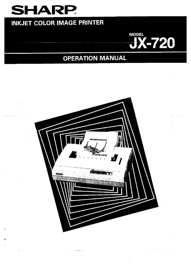
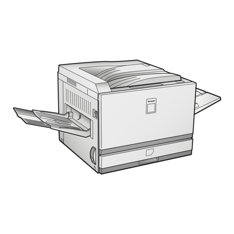
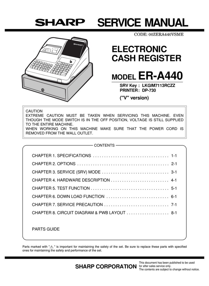
Sharp CE-140P User manual

C~L
[
(
ft-
5
°
C
t
o
40
°
C (41
°F
to
104
°
F)
2
56
(
W
)x184(D )x43(H )mm
10
-
25
/
32"
(W)x7-1
/
4"(
D
)xl
-
11
/
16"
(H)
A
pprox.
860g
(1
.
9 lbs.)
A
C
Adaptor
(EA
-
150), Hard
case
,
1
roll of paper,
1
spare ink
cartridge
,
Cleaning kit
(1
cleaning cartridge,
1
cleaning paper,
1
cleaning pad),
Operation manual.
Weight:
Acces
s
or
i
e
s
:
Operating
temperature:
Dimensions:
S
H
ARP CORPORATION
0.2mm
Maximum of
6
.
1
char
ac
te
rs
/
s
econd
(when
t
h
e
standa
r
d
s
i
ze
cha
r
acter
"2
"
i
s
pr
i
nted
i
n
black
.
The
printing
spe
e
d
va
r
ies
dep
en
di
ng on
the format
and
cha
r
a
c
te
r
type
being
pr
i
nted.)
moveme
n
t
:
P
ri
nting
Speed
:
CE-140P
Colour Dot
Printer
X, Y
Plotter
Max
i
m um of 80
(smallest character size)
7 (Black, Purple, Red, Magenta,
Green, Cyan, Yellow)
4
(
B
lack,
Mage
n
ta,
C
yan,
Yellow:
E
A
-600 Ink
Cartr
i
dge)
Black:
Approximately 1,600,000 dots
(approximately 66,000 standard
s
ize
"2"
characters)
Other colours:
Approx
i
mately
960
,
000 dots
(approximately
40,000 standard
size
"2
"
characte
rs)
Printed
at
20
°
C
(68
°
F)
Character
s
ize
:
63
typ
es from
0.8
mm x
1
.
2 mm
to
50".4
mm x
75.6
mm
Charact
e
r
p
r
inting
direction
s
:
4
(Up
,
Down
,
Left
,
and Right)
Minimum head
adaptor
Power
consumption:
5.2W
Number of
line
s:
A
p
prox
i
matel
y
450
(wi
t
h
1
5
-h
o
u
r
ch
ar
g
e)
(
A
t
a
t
e
m
peratu
re
o
f
a
pp
ro
ximat
e
ly
20
°
C
(
68
°
F
)
,
s
t
a
nd
a
rd
s
i
ze
"
2
"
chara
c
te
r
s
p
r
in
ted
in
b
l
ack
,
and
twenty
"
5"
charact
e
rs
p
rint
e
d
p
er
lin
e
.
P
a
per
:
Roll
pape
r
diam
e
t
e
r
25 mm
o
r
les
s
,
width 114 mm
(Option:
EA-51
5
P)
Powe
r r
equirements:
Built
-
i
n rechargeable
batt
e
ry
AC: Local voltage with EA
-
15
0 AC
Ink life:
Ink
c
olours:
Printing Colours:
Model:
Product:
Printing
method
:
Characters
/
line
:
1. SPECIFICATIONS
•PARTS
LIST
&
GUIDE 28
•
PRINTER SECTION
1.1
GENERAL DESCRIPTION
11
1
.
2 OPERATING PRINCIPLES 12
2.1
REPER 16
3.1
DISASSEMBLY
19
3.2 ASSEMBLY 19
,.-~~~~~~~~~~~~~~CONTENTS~~~~~~~~~~~~~~--
1.
SPECIFICATIONS
1
2. SCHEMATIC DIAGRAM OF THE SYSTEM
2
3. NOTES FOR HANDLING THE
CE
-
140P 2
4.
CE
-
140P CIRCUIT BLOCK DIAGRAM 3
5.
EXPLANATION OF CIRCUIT OPERATION 3
6. EXPLANATION OF CPU
TERMINAL
SIGNALS 4
7. HOW TO CHECK OPERATIONS 5
8
.
ADJUSTMENT IN THE CIRCUIT
9. CIRCUIT DIAGRAM
10
.
PARTS
&
SIGNAL POSIT
I
ON
•
Printer of ink-dot plotter method and 7 colours
•
Use the operation manual with this
text
MODEL CE-140P
COD
E:OOZCE140PSM
/
E
SHARP -
CE
-
140P
SERVICE
MANUAL

Table 3.
Tempe
r
at
ur
e
C
harging voltage
0
°
C
Mo
re
tha
n
7.
5
V
2
0
°C
Mo
r
e
tha
n
7
.
2
V
40
°C
M
ore
t
h
an
7
.
0V
T
ab
l
e
2
.
2
)
C
a
p
acit
y af
t
er
leavin
g
bat
t
eries
A
fter
co
m
p
l
et
i
ng charging, if
a
battery
is
l
e
ft for
a
m
onth
at
t
h
e
t
em
p
e
r
a
t
ure of 20 ±
2
°
C
,
the
disc
h
arge
c
apacit
y
i
s
300
MAh
o
r
mo
re
.
4.
Ch
arac
t
eris
t
ics of
t
he
cha
r
g
i
ng
vo
l
tage
C
harging
volta
g
e a
ft
er
c
ha
rgi
ng
c
on
tinuou
s
l
y
wi
t
h
5
0
m
A
stea
d
y
current
o
f 15
ou
rs
a
r
e
g
iven
in
T
able 3.
Ch
arge or
dis
ch
arge
t
e
mp
e
r
at
ur
e
Di
scha
r
ge
c
a
p
acity
10
±
2
°C
50
0m
A
or more
20
±
2
°
C
5
00
mA
o
r
more
35
±
2
°C
4
00
m
A
or more
3
.
Discharge
ca
pacity
Charge and discharge are
performed at the
same
tempera
-
ture
,
and
the
final discharge voltage
i
s
5.0V.
Standard
charging Charging
is
pe
rform
e
d w
i
th
5
0mA
for
15
hours,
discharge is
performed with
1
O O
mA
steady
curr
e
nt
.
1)
Discharge
capacity after
charging
The
d
i
scharge
capacity
w
i
thin
a
n
hour after completing
charg
i
ng
is
given in Table 2
.
Tabl
e 1.
No
-
l
o
ad
t
e
rmin
a
l
volta
ge
Time
el
a
ps
ed MIN
MAX
F
or
a
n h
ou
r
o
r
l
es
s
6.50V
7
.
50V
After
a
Month
6.25V
6
.
75V
T
i
m
e
fo
r
c
h
a
rg
ing
1
5
h
o
u
rs
Trichle
c
h
arg
i
ng
current
:
10~
25
mA
Temperature
ran
g
e
fo
r
reservi
n
g
:
-
20
°
C
~
40
°
C
(
l
ess
t
h
an
8
5
%
)
2.
In
t
h
e
te
mp
era
tu
re
r
ang
e
of
25
±
5
°
C,
no-lo
ad
term
i
nal
volt
a
g
e
s
a
ft
er co
mpl
e
ting
ch
a
r
gi
ng are
g
iv
e
n
i
n
T
a
bl
e
t.
The charg
in
g
mu
st
b
e
pe
r
fo
rm
e
d in
t
h
e
t
e
mper
a
tur
e
ra
nge
g
i
v
e
n
above
with 50mAfor
1
5
hou
rs
.
5
00mA
h
(0
.
2
C
dis
c
harge)
50mA
Nomi
nal
capacit
y:
C
harging
curren
t
:
Reference data
1.
R
a
t
ed
v
a
l
ues of a b
a
t
tery
of
charg
ing
ty
pe
N
ominal
volta
g
e
:
6
.0
V
•
If
a
batter
y
is
charged
fo
r
a
while more
t
han
t
h
e
specifi
-
ed
time
,
overcharge
occurs
,
and
the
batter
y
perform
a
nce
sometimes
fal
l
s.
•
If
charging
i
s
performed
when
the
tempera
tu
re
is
5
°
C
or
l
ess or
40
°
C
or
more,
t
h
a
n
battery
performa
n
ce some-
times fal
Is
.
•
A
f
t
er
repea
t
ing several times charge
a
nd
d
is
charge
co
r
rectly,
if
the battery
can be used only
for
half of
the
prescribed
time
,
cons
id
er
t
h
e
l
i
f
e
of
the
battery
,
and
cha
n
ge it.
-
2
-
General knowledge
of
batter
i
es
of
cha
r
gin
g
t
y
pe
•
I
mm
edi
at
ely
after
pu
r
chasing
a
product,
it seldom
happ
ens
t
h
at
a
battery cannot
be used for
a
pre
s
cribed
wh
ile
af
te
r
cha
rg
i
ng
s
u
ffic
ie
n
tly
(more
than
1
5
hours).
In
su
ch
a
ca
se
,
th
e ge
n
e
ra
l
co
nd
iti
on will be
re
t
urned
while it
is
used
aft
e
r
c
ha
r
g
in
g
2 o
r
3
t
imes.
•
Whe
n
a
b
atte
r
y
is
not
u
se
d
for
a
l
ong w
h
ile,
th
e
ba
tte
r
y
capacity
is
lower
e
d by
s
elf
-
d
i
s
c
harg
e
.
•
Power
supply
In
the
CE
-
140P
,
a
b
a
tter
y of
c
h
arg
in
g
ty
p
e
(
ni
ckel-
c
admiu
m
s
tor
a
g
e
ba
tter
y of
her
m
e
tic
t
yp
e)
i
s
used as
a
power
source.
Th
is
b
a
tt
ery
o
f
c
harg
ing
type supp
l
ies
the following
s
:
1
.
V
o
lt
age
for
o
p
era
t
ing
a
pri
n
ter
(voltage for
operating
a
m
o
t
or
o
r
a
h
ead)
:
Vp
=
6.0
±
0.
5V
2.
Lo
g
i
c
cir
cu
i
t
op
e
ration volta
g
e
(pri
nt
er
contro
l
circuit:
V
ee=
5.0 ± 0.5V
Ho
we
v
er
,
t
he
p
ower
is
n
ot supplied
from
the
CE-1
40
P
to
a
com
pu
t
e
r.
•
How
to attach
roll
paper
.
•
How
to
exchange an ink ca
r
tridge.
•
How
to
clean
a
printer
head
.
(How
to
use
a
cl
e
an
i
n
g
k
i
t.)
•
How
to
clean
a
printer
.
(How
to
use
a
cle
an
i
ng
k
i
t
.)
•
How
to connect the
CE
-
140P
with
a
computer
.
•
Range
for
moving
a
head
o
r
pap
er
(p
r
int
i
ng
are
a
).
•
In
s
tructions for the
CE
-
140P.
As
fo
r
the
items given
ab
o
ve
,
r
efer
to the
o
p
era
tio
n
manu
a
l
.
3.
NOTES FOR HANDLING THE
CE-140P
CE
-
5
1
5P
Fig.
1
CE-1
2
6P
P
C
-5000
C
E-
516L
G--0--0
~
C
E
-130T
[)-0{)
II
SIO
l
/
F
CE-515
P
etc
.
2. SCHEMATIC DIAGRAM OF THE
SYSTEM
-
CE
-
1
4
0P

-
3
-
N
i-
cd
terminal
A
pprox.
6
.
5V
Approx
.
7.
5V
A
pp
rox
.
7.75V
voltage
( i
nit
i
al
st
age
of
(
T
yp
.
)
(l
ast
st
a
ge
of
chargin
g
)
c
h
ar
ging
)
Chargi
ng
A
bo
u
t 117mA Abo
u
t
5
1
mA
About
5
.
3mA
cur
r
e
n
t
Fig. 5
C
ircuit
s
ec
ti
o
n
B
in
t
he
blo
c
k
d
i
agram
1)
T
his
is
a
c
i
rcuit
u
sed
to
cha
r
ge
Ni
-
cd
battery
by flowing
a
pp
ro
x. 50 mA on RO when
a
p
r
i
nter
is
not
op
e
rat
e
d
.
2
)
C
h
a
r
ging
c
ur
r
e
n
t
v
ar
i
es
depen
di
ng on
t
he
s
tatus
of
N
i-c
d
battery
capac
i
ty (terminal
voltag
e
)
.
Th
e
ra
n
ge of
t
he
va
r
ia
t
io
n
i
s
g
i
v
en
below
.
-:-
N
i
-Cd
_
:_AAx
5
I
I
0
3
I
I
l---
- J
Po
w
e
r
s
upply
,___
__.t--'-A~s~e-ct~io~n
..._~GND
DO
01
A
DAPTO
R
•
S
e
c
tion
B
:
Po
wer
su
p
ply
circui
t
Th
is is
a
c
o
n
trol circuit
i
n
wh
ic
h
the output current
of the
A
C
ada
pter
i
s
co
ntro
l
l
e
d
n
ot
t
o
e
xceed
max
.
500
m
A
usi
n
g
the
R
1
and
T
r
1
.
C3
,
R
3 and
02
are used
to
rise
the
pow
er
s
upply
circuit
by
fl
owing
b
a
s
e
cu
r
re
nt
(03
-+
02
-+
Tr
3
-+
R
4) on
the
T
r
3
w
h
en
the
AC
a
d
a
p
ter
is
con
n
ected.
2)
Whe
n
th
e
N
i
-
c
d
te
rm
i
nal
vol
t
ag
e
i
s
6.0V
o
r
more,
t
h
is
c
irc
u
i
t
is
sca
rc
el
y
ope
r
a
t
e
d.
3
)
Wh
en
th
e
bat
t
e
r
y
c
ap
a
city
is s
m
a
ll
,
if
a
pr
inter
i
s
o
p
era
t
ed,
t
h
i
s
ci
r
c
u
i
t
i
s
operate
d
f
u
ll
towarddetecting
l
ow
ba
tt
e
ry
(5
.
3V
)
.
T
h
a
t
i
s;
w
hen
t
h
e
batt
er
y
vo
l
tage
is
l
ow
ered
to
5
.
5V
b
y
p
ri
nt
er
o
p
erat
i
o
n,
the
e
l
ectric
pot
en
t
i
a
l
in
t
he
catho
d
e
side
(
T
r3
co
l
lec
t
o
r)
o
f
the
zen
e
r
diod
e
0
3
i
s
a
l
s
o
lowered
,
and
the
em
itte
r
e
l
ec
tr
ic
p
o
t
en
t
ial
of
Tr3
is
more lowered (get
nea
r
to
GNO
l
evel) on
acco
u
nt
of
co
n
stan
t
-
v
olt
a
ge
e
ffec
t
of
the
zener diode
03.
Accordingly,
the
increase of
the
collector current
o
f
Tr3
cause
s
the
increase
o
f
th
e
cu
rren
t
o
f
th
e
co
ll
ector
and
the
emitte
r
of
Tr
2
.
There
-
fo
re,
c
urre
nt
s
u
pp
l
y
is
passible
w
h
en
the battery
capa
-
ci
ty
i
s
smal
I.
4)
Wh
e
n
th
e
s
u
pp
l
y
cu
r
rent
is
i
ncreased and
th
e
AC
a
dapte
r
outp
u
t
c
u
rre
n
t
i
s
50
0m
A or more,
T
r1
cut-off
el
ec
t
ric
pot
e
nt
ial
is
ex
c
eeded
(R
1
x
5
00
mA), and Tr1
is
ON
-
Tr
2
i
s
OFF,
so
that
t
he
cu
rrent
supply
i
s
stopped.
S
in
c
e
the
pri
n
te
r
o
peration
vo
l
tage
is
the
sa
m
e
as
t
h
a
t
o
f
the
Ni
-
cd
discha
r
ge voltage,
th
e
Ni
-
cd
t
e
rmi
nal
volta
g
e
Vp
i
s
connect
e
d
dir
ec
tly
.
Section
A
:
When
the
cap
a
c
i
ty
o
f
a
Ni
-
cd
batte
r
y
is
sm
a
ll
,
(wh
en
th
e
lo
w
-
ba
tt
e
ry
is
not
d
e
tected), th
e
volt
a
ge
sam
e a
s
the battery
voltage
is
direct
e
d
from
t
h
e
ad
a
pt
e
r
to
suppr
e
ss
bett
e
r
y
consump
-
tion
.
S
e
ct
io
n
B
:
Th
is
is
a
c
i
rcuit
us
e
d
e
xclus
i
v
e
ly for
cha
r
ging
a
N
i-
cd
battery
.
S
e
ction
C:
T
h
is
is
a
V
ee power
sup
p
ly
cir
cu
it
u
sed for
a
logic
circu
i
t
(prin
t
er
contro
l
circui
t
)
.
Fig
.
3
GND
B
~
Vp
-=- '
tl
vcc
NI
-
Cd
A
s
.
w
.
1
.
P
owe
r
supply cir
c
uit
F
i
g
.
3
s
h
ow
s
the
b
loc
k
d
i
agram of a
power
su
p
ply
circui
t.
5. EXPLANATION OF CIRCUIT
OPERATION
Fig.
2
-+--
-
;>o.VCC
AC
Adapto
r
E
X
-
150
----
Powe
r supply
(N
l
-
cd
AA
x 5
P
CS
)
Lo
w
battery
15PIN
COI
L
Fig
.
4
Circu
i
t
se
c
t
io
n A in
t
he
b
l
ock
d
i
ag
ram
C
l
ock
I
N
K
1)
S
IO
8
Motor
8
dr
i
ver
d
ot
pl
o
t
t
er
-
P
rinte
r
Head 4
b
ri
v
er
M-374
0
:::t-!
N
i
-
Cd
!
:
IAAx
5
L
-=r
•
_
_j_J
I
I
0
1
04
R
1
A
D
AP
T
OR
•
Se
ction
A
:
P
ow
e
r
s
up
p
l
y
ci
rc
u
i
t -
C
E
-
1
4
0
P
15 PIN
V
p
SC
6305Y1
A3
9
P
CPU
SIO
INK Pf
P
R
INTER
SI
O
v
cc
0
4. CE-140P CIRCUIT BLOCK
DIAGRAM

-
1
-
Terminal
Terminal
Input
/ Explanation of
signals
No
.
name
Output
1
Vss
Powe
r supply
ov
2 RES
Input
Power ON reset
input
te
r
minal
3
INT Input
Interrupt
i
on
input terminal
when
a
low
battery
is
detected.
(In
genera
l,
h
i
gh level, when LB
is
detected, low
level
)
4 STBY
Input
Pull
-
up and
fix to
Vee
.
•
5
XTAL Input
4 MHz
oscillator connection terminal
6
EXTAL Input
4 MHz
oscillato
r
connection terminal
7
NUM
Input
Pu
l l
-
up
t
o
Ve
e
at 10
K
!1
.
8
TIMER Input
Fix
to
GND
=
OV
.
9 PA7
Output
Paperfeed (Y)
motor
D phasestart
s
i
gn
a
l
1
0 PA6
Output
Pape
r feed (Y)
moto
r
C
phase
s
t
a
rt
s i
gnal
11
PA5
Output
Paper
fe
e
d (Y)
motor
B
phasestart
s
i
gn
a
l
12 PA4
Output
P
a
pe
r feed (Y)
motor
A phase
start
s
i
gnal
13 PA3
Ou
t
put
Carriage
f
e
ed (X)
motor
D
phase
st
a
rt
s i
gnal
14 PA2
Output
Ca
r
r
i
ag
e
f
ee
d (X)
motor
C
pha
s
e
start signal
15 PA1
Output
Carriage
f
ee
d
(X)
m
o
tor
B
phas
e
start
s i
gnal
1
6 PAO
Ou
t
p
ut
C
ar
r
iag
e
f
ee
d (X)
m
otor
A
ph
a
s
e
st
a
rt
si
gn
a
l
17 PB7
Ou
t
put
SID
"
RD
"
s
i
gna
l
1
8 PB6
Ou
t
put
SIO
"
CS
"
s
i
gna
l
19 PB5
Outp
u
t
PRINT
+->
ex
t
erna
l
S
I
O
s
elec
t
s
i
g
n
a
l
(b
uf
fer
IC
en
ab
le
sign
a
l)
20 PB4
Ou
t
put Print
signal
,
whe
n
th
e
he
a
d
driv
e
s
ignal
i
s
gen
er
ated,
low
l
evel
.
21
PB3
Output
H
ead
p
in
d
r
iv
e
(ye
l
low)
s
ignal
,
high
lev
e
l
i
s
available.
22 PB2
Output
He
a
d
p
i
n
dr
i
v
e sig
n
a
l
(ma
z
ar
i
ne)
signal
,
high
lev
e
l
i
s
avilable
.
23
PB1
Output
Headpin drive
signa
l
(cyanic) signal, high
l
e
v
e
l i
s
available
.
24
PBO
Output
H
ea
d
p
i
n
drive
(blac
k
)
s
i
gnal
,
h
i
gh
lev
e
l
is
av
ai
lable.
25 PC7
-
N
.
C
I I
-
I
27 PC5
-
N.C
28 PC4
Inpu
t
C
ar
ri
a
ge
hom
e
p
os
ition
d
e
te
c
tio
n
sig
na
l.
On
ly
th
e
hom
e
p
osition
is
at high
l
e
v
e
l.
•
SC6305Y1
is
a
single chip micro
computer
of 8 bits.
(Internal
ROM
=
7872
bits,
RAM= 256 bytes, extension of
an
external
8K
byte
RAM
is
possible
.
)
6.
EXPLANATION OF CPU TERMINAL SIGNALS
Fig. 6
Circuit
section C in the
block
diagram
T
h
e
logic voltage Vee
is
generated with Vp voltage.
S
i
nce
the
Vp
vari
es from 5.5V
to
6.5V
wh
e
n
a
printer
is
operat
e
d
and varies from 6.5V
to
7.7V
w
hile
ch
argin
g,
th
e
ze
ne
r
charactristics
are used. The
stab
i l
i
zation of
act
i
va
t
ion at
starting time
is
accomplished with C1,
R1
and 01 which
have
the
same
charactristics
as
the
of
C1
,
R
1
and 01
i
n
circuit
A.
R4
D2
R2
Tr
1
Vp ~--
.....
------. ,----41------...-----.,l
J
V
ee
•
Section C: Vee power supply
circuit
-
CE-140P

-
5
-
2
)
Charactertest
funct
i
on
Thi
s
is
a
function to
ch
e
ck
the print status
of
character
s.
Turn on
t
h
e
p
o
w
e
r
supp
l
y switch
with
pr
e
ss
i
ng
th
e
paper
fe
ed
key
.
Then, printing characters
(l
e
tter
s
or
num
er
ic
s
)
c
ontain
e
d in
this
machin
e
is
s
t
a
r
ted.
Wh
e
n
printing
c
h
a
ra
c-
ter
s
i
s
c
o
mp
lete
d once,
r
es
t
a
rt
p
r
inting from
the
begi
n
ning
a
f
t
e
r
e
xc
h
an
g
i
ng
i
nk
.
(Ink
c
a
n
b
e e
xch
ang
ed in
th
e order of
bl
ack -+ cy
a
n -+
mag
e
n
ta -+ y
el
low
.
)
Whe
n
pr
i
nt
i
ng
is
t
o
be
term
i
nat
e
d
,
t
urn off
thepow
e
r
supp
l
y
switch
.
1)
C
o
lo
r
te
s
t
function
Th
i
s
is
a
functionto
ch
e
ck head
stuffing
or ink
exhaustion
.
When
the
form feed key
is
pressed w
i
th
pre
s
sing
the
ink
e
xchange
k
e
y
,
a
s
qua
re of which
sid
e
l
e
ngth
is
5mm
is
d
r
awn
i
n
th
e
hatching
form
with
e
a
c
h
color. The
ord
er
of
colors
is
as
follows
:
Bl
a
ck,
purp
l
e
,
red
,
magenta
,
green, cyan, yellow.
7. HOW TO CHECK OPERATIONS
Term
i
nal
T
e
rm
ina
l
I
n
p
u
t
/
E
x
p
la
nati
o
n
of signals
No
.
n
ame
Outp
ut
2
9 PC3 -
N
.
C
3
0 PC2
Ou
t
pu
t
L
ow
b
at
t
e
ry
d
e
t
ec
t
ion
s
upport
si
gn
a
l (
wh
en
LB
is
de
tec
te
d,
hi
gh
.
Ve
e
po
w
er
s
upp
l
y in
t
h
e
moto
r
I
ci
r
c
uit
i
s s
t
opp
e
d
.
)
3
1
PC1
Inpu
t
J
a
p
an
t
yp
es
ar
e
pu
l l
ed
-
up
t
o
V
ee
at
10K
n,
a
nd
Expo
r
t
typ
e
i
s
pul
l
ed
-
dow
n
t
o GNDat
10K
n
.
32
PCO
I
n
put
PRINTER
+-+ SIO
selec
t
s
i
gn
al.
P
rin
t
er side=
l
o
w level,
S
I
O side=
h
igh
l
e
ve
l
.
33
V
ee
Pow
e
r
supply 5
±
0.5V
34
PD
1
Inp
u
t SIO
"
SD
" input
s
ign
a
l
35 PD2
I
n
put SIO
"
RS
"
i
npu
t
sig
n
al
36
PD
3
Input SIO
"
RR
" input
sig
n
al
37 PD4 Input
I
1NK
I
k
e
y
inpu
t
sig
n
a
l.
V
ee
le
v
el
is s
et by key
ON
.
3
8
PD
5
In
p
u
t
I
m
I
key
i
npu
t
sig
n
a
l.
V
ee
lev
e
l i
s s
e
t by key
O
N
.
39
INT
2
I
npu
t
I
n
t
erruptio
n
sig
n
al.
Lo
w
le
v
e
l
is
a
v
a
i
labl
e
.
40 PD7
I
n
pu
t PAK
(
peri
ph
e
r
al
ack
no
w
l
ed
g
e)
sig
n
al.
Hi
g
h
effective
s
i
g
nal
ge
n
e
r
ated with PRO
(
p
eripheral
req
ue
st)
sig
n
a
l
.
41 AO Output
N
.
C
1
1
1 1
54 A13 Output
N
.
C
55 RJW Output
N
.
C
56
E
Output
N
.
C
57 D7
Input
/
Ou
t
put
N.C
.
l
1
1
1
64
DO
Input
/
Output N.C
-
CE
-
14
0P

-
6-
ABC
D
..
...
X
Y
Z
0
12
3456
7
8
9
+
-
*
I
(In each
color
,
bolt,
s
t
a
i
n
i
n
the
space
,
blur,
o
r
t
r
a
n
sfor
m
atio
n of
printed
chara
c
ters
i
s
not
all
o
we
d
.)
@llllll
I
IIIIJ1UIJ}
~
/// /
Gap in
t
h
e
Y
direction
m
u
st be
0
.3
m
m or
l
ess.
~
-,,--,
r
i
'~-
_
__,,_,_
.
(
J_~
e~
l
:
w
~",
}
,~
?·
,
G
a
p
i
n
th
e
X
d
i
r
ection
'
1+-'
, ;
m
ust be 0.2mm or
less
.
:
1
Cyan
,·
:'
:
µ_Mag
e
n
t
a
'
:
~
'
:
1
)
:
,
J
'
Q
'
i:...:.:
--
-
- -
-----
..
:.
f
-
T-
-
J
=r
-
-'
Yel
low
M
a
g
e
nt
a
Cya
n
Th
ey
mu
st
a
p
p
ea
r
in
th
e
sa
me line
a
s
t
h
a
t
o
f
bl
ack.
I
n
the
disp
l
a
y
of
th
e
P
C-1450
,
"ER
RO 8
IN
"
must
a
pp
e
a
r.
Printer
head
must
be in
th
e
rightmost
po
s
it
io
n
.
Paper
fe
e
d
i
s
prohib
i
t
e
d
.
H
ead must
b
e
in
the
leftm
o
st position
.
Set
t
h
e power
sw
i
tc
h
to
ON
.
IC-CE
I
I
DEF
I
0
S
witch OFF
po
int
I
9--
,
~-
~-----
-
--
r
-;
When
p
r
inting
prog
r
essed up
to the position
s
hown
b
e
l
ow
,
s
et the
pow
e
r
s
witch
to
OFF
.
•
Pr
es
s
j
1
N
K
J
k
e
y and
s
e
t
i
t
fr
ee
.
Pre
ss
[WJ
key.
P
r
ess
J
1NKI
k
e
y
a
nd
s
et
i
t
fre
e
.
•
POWER SW ON
•
I
BASIC
I
lliJ
[]
I
ENTER
I
•
•
•
•
•
P
oint to
b
e
ch
e
cked
Ope
r
ation
CE
-
140P
PC
-
1450
3)
Charcter of printed
c
haracters
,
or
che
c
k
i
ng
p
r
int
preci
-
s
i
on
•
P
repare
the
PC-14
5
0 (E
L
-
55
2
0)
to
co
n
nect
with
the
C
_
E-140P which
is
to
be
tested
.
• Enter the
cke
c
k
program
in
the
PRO mode, and carry
cut the
following
operation:
-
CE
-
1
40
P


Ambienttemperature
(
°
C)
Vp(V) LB(V)
0 5.49±0.01
1.0
±
0.1
5 5.45
±
0
.
01
1
.
0
±
0
.
1
10 5.41
±
0
.
01
1.0
±
0.1
15
5
.
38
±
0
.
01
1.0
±
0
.
1
20
5
.
34
±
0
.
01
1
.
0
±
0
.
1
25
5.30
±
0.01
1
.
0
±
0
.
1
30
5
.
26
±
0.01
1
.
0
±
0
.
1
35
5
.
23
±
0
.
01
1
.
0
±
0
.
1
40
5
.
19
±
0
.
01
1.0
±
0.1
1)
How to adjust voltages in the low
battery detection
circuit.
A
d
j
ust the
RV
(220K
~
)
to
c
o
rres
po
nd
t
o
t
h
e
meas
u
re
d
a
m
bi
ent
t
e
m
pe
r
a
t
u
r
e
s
o
th
a
t
t
he low
b
at
t
er
y
m
ay
b
e
d
et
e
ct
e
d
at
th
e Vp
vo
l
t
ag
es
g
iv
e
n
in
t
h
e
fo
l
low
i
ng
tabl
e
.
(S
et
VR
i
n
the
full
clockwis
e
direction
,
then, adjust
by
slowly
rotat
i
ng
leftward
.
)
8. ADJUSTMENT
IN
THE CIRCUIT
360:LPRINT
"R-100,-225"
400:REM
**
Y
RUISEKI
**
410:LPRINT
CHR$
27+"C0":
LPRINT
"R100,"
420:FOR
A=0
TO
4:
LPRINT
"J,-999,10,,,99
9,10,":
NEXT
A
430:LPR!NT
"
J,-996"
440:LPRINT
CHR$
27+"C3"
450:LPRINT "J-150,,,-3,150,,,-3,-150,"
460:LPRINT
"R-50,-200"
500:REM
**CHARACTER**
510:LPRINT
"A"
520:FOR
A=0
TO
5:
LPRINT
CHR$ 27+"C";CHR
$
(48+A>;
530:LPRINT
"ABCDEFGHIJKLMNOPQRSTUUWXYZ01
23456789+-*/"
540:NEXT
A
600:LPRINT
CHR$
10;C"HR$
10;CHR$
10;CHR$
10;CHR$
10;CHR$ 10;CHR$
10
610:END
"'
2
J
c
RINT
"R
- 5,
,5,
"
270:LPRINT
"J,-25,-25,"
280:
L
PRINT
CHR$ 27+"C3":
LPRINT
"J-25,"
290:LPRINT
CHR$ 27+"C5":
LPRINT
"J-25,"
300:LPRINT
CHR$
27+"C6":
LPRINT
"J-25,
"
310:LPRINT
CHR$
27+
"
C0":
LPRINT
"J-25,,,
25"
320:LPR!NT
CHR$
27+"C3
"
:
LPRINT
"J,25"
330:LPR!NT
CHR$
27+"C5":
LPRINT
"J,25"
340:LPR!NT
CHR$
27+"C6":
LPRINT
"
J,25"
350:LPRINT
CHR$
27+
"
C0":
LPRINT
"J,25"
240:LPRINT
"R,S,,-5":
LPRINT
"J25,":
LPR
INT
"R,-5,,5":
LPRINT
"J25,,
,-25"
250:LPRINT
"
JS,,
-
s,,,-25,-5,,5,,,-25
"
260:LPRINT
"
RS,
,-5,
"
:
LPRINT
"J,-
2
5":
LP
10:REM **TEST
fo~
CE140P
**
20:CONSOLE
160
100:LPRINT
CHR$
27+"1i"
110:REM
**
X
ERROR***
120:LPRINT
CHR$ 27+"b"
i30:(PRINT
CHR$ 27+"b"
140:LPRINT
"LS":
LPRINT
"0480,-40,B"
200:
"
A"
REM**
X&Y
ERROR**
210:LPRINT
CHR$
27+"b
"
220:LPRINT
"M100,-100"
230:LPRINT
00
J2s,,,s,,-s,2s,,,-s,,s,2s,,,
•
Check program
-
7
-
ABCDEFGHIJKLMNOPQRSTUUWXYZ0123456
7
89+-*/
ABCOEFGHIJKLMNOPQRSTUUWXYZ0123456789+-*/
ABCOEFGH
I
JKL
MN
OPQ
R
STUUW
X
YZ01234
5 6
7
89+
-
*
/
ABCDEFGH
I
JKLMNOPQ
R
STU
U
WX
Y
Z0123456
7
89+-
*
/
ABCOEFGHIJ
K
LM
N
O P
Q
R S
T
UU
WXY
Z012
3
456
7
89
+-t/
L
II_
·
- -
I
----------------
-
----
-
- -
----------~
2"#$%&'(
)*+,-./0123456789:;<=>?@ABCDEFGHIJKLMNOP
2"#$%&'<)*+,-./0123456789:;
<
=>?@ABCDEFGH
IJKLMNOPQRSTUUW
XY
Z['J._'abcdefghijk
l
mnop
q~stuvwxyz
{:}
-a
r
~
.
a374~
~
Xt?.:i.3
~-
7{'I
~
nf~
1~
1J:.i:zt":J'5'f''..lf
I ·
t
.:.
x
i
;
i
'lt
"J
"-
:t-7:.c:..J~t'
J:i7
1
J
11..vo?::...
''
0
0a,q
8M~<:>~+nH
"
#$"
;&'
(
'it+, -
.
/
0
1
2
3
455
::-)
8
9
:
;
<
=
>
?
ij
AB
C
OE
FGH
I
Jl<.U'll~ODQPS
TUU
l
•
l
><
"
i'Z
[
¥
J
.
.'
abc
de
fgh
ijk
l
m
n
opq
~
stuvw
~
yz
l
:
l
-
a
r~
~3Y4'i~f?.:i.
3
~-7{
·n~
n
:t
:i
'.T:J1t:;7.
t
'J
'.?f
"
Jf
I
·
+
.:.
:
rf:
.
J,
·
,
t
;
'
·.
:f:
T:
.
.:.
J
f:
t' 1:i
7
'.l
1Lv
o
-;i
:.
,
,·
0
0
4
!,'JG
Fl
~o
,:
·
+
nr
2
"
#$'.
,
:&
'
(
:
i
!:
+
,
+ ,
/
012
.
34587
8
9:;
<
=
>
?
@
AB
C
OEFG
H
I
J
K L
MNOPQ
R
ST
U
U
W
X
YZ
[¥J
ab
c
def
ghijklmnopq~stu
vw
xyz
{
:
l
-cr
~
,
c3~~'
z
:>tt?
as
·
~
·
-
J'
("'JI1!J'f~
'J
J
tt
:..J
7
t
'
)
'.71-
'~
Jf
I
·
t.:.;?
f:
J
1
·
1
t
"J
'
•
1'
·
:;i
=.c,/
e+
J::i-=.
1
,1
1
u
,o
-;i:.,
·'
0 0
4
f:JB
Fl
·
.;>c:i
>
+
IT
.f
••••••
• Print
samples
to
be
tested
(some kinds
of
colors do
not
appear
in
print
.
)
-8
-
<Fig- 8)
1
.
0
±
0
.
1
1
.
0
±
0.1
1
.
0
±
0.1
1
.
0
±
0.1
1
.
0
±
0.1
1
.
0
±
0.1
1 .
0
±
0.1
1.0
±
0
.1
1.0
±
0.1
LB(V)
(
PB0
~
3
)
PRINT
!.
t,"
._:
__
..___,
TC74HC02P(Out)
-----'~~'---------!~'-:
-----
Print pulse
I
I
i--.1
I I
0.68msec
TC40H367P
(O
u
t
)
'
t
h
e
m
easured
attery
m
ay be
f
ollowing
table
.
t
hen, adjust by
ttery detection
(
PB4
)
TRI
GGER
n-=:-------~n
~
2
0µ
2
.
86
m
sec
:------
:IRCUIT
GND
0;CHR$
BA6521
TC40H367
P
VWXYZ01
(
P
B4
)
TRI
G
GER
"C";CHR
-ria
I
I
I
L-------
V
ee
Vp
150,"
- -
-,
I
II
I
I
I
I
STA401A
I
---'
r-------
TC74HC02
P
R100,"
10,,,99
HEAD
CO
I
L
#
1
~ #
4
(
P
B
O
~
PB
3
)
PR
I
N
T
...._
--'.,--.....
Vp
J,25"
J,25"
J,25"
J,25"
Vp
J -
25,"
J-25,
"
J-25,"
J-25,
••
2) How to adjust a head drive circuit (print pulse width)
Adjust
a
pulse
width (printer
head coil applying pulse,and
C
terminal
of
the STA401A)
to
b
e
0.68m
s
e
c. using VR1
whenthe
Vp
voltage
i
s
within
6.0
±0.05V.
-25"
25":
LP
Fig.
7
,
":
LPR
5,25,,,
RV
,B"
LB
02
01
Vp
-
CE-140P

-
9
-
I
OK
IS:Ok:
FG
so
RD
R
S
cs
DR
SG
I
CD
C
l
:
VC
(
l
)
:
RR
I
(
NC
)
V
C
(2)
I
ER
:
(
NC
)
I
r-
-- - -
I
I
F
G
S
D
R
D
R
S
cs
D
R
SG
CD
Cl
VC(l
RR
P
AK
I
VC
1
2
ER
PRQ
L _
K
E
Y
-
-
-----
-
---
r--""E_-;--
,,-- _M_
r+': M
,,-- Jl'L
,-- _u
'
r-r--:
...8.3...
r=»:
..fl!_
,,--
.ss.
•
r:
_Q2__
i~
r
__Q_J_
10
•
v- ~
PWB
-
-f--..§!J!_
_
I
--
-
-
-
-
--
-
[
-
·
·
·
·-
·
-
--
-
·--
-
I
-
~
I
-
-
--
.,
'
~
I
~'£Vi
c
I
~
l
~
tc
PP
!
l
'
S'J-
fJ
TC4
0C
-
~
I
'
~*Vu
:
I
-
~
*
/'~J
I
TC4
08
1
:~
,
,
;-
u:
oi-!-
'
-
'
I
'
I
'
n:
~
,
1
I
(
(
(
,_
-
11
,
0
·-·~~~
~~~-~
~
-~~-·~rl
-0
~
·~~
mN-U
'
f
l
I
~
1
~1
a
la
~
1~1C>
l
al"
I
;,.
d
l
~l"°
/
~
I"°
<{
1
~1<l~
1
<{
~
1<{1<(
1<{
1
~11~
~1~
1~1
~1~
1~
I
J
-
:
"
I
Ii
,.
6• JS
.t
o
9-
.1
{<b
Jr
.
,
I~
I
I
-
~
!~c
•
'
-
N
"""
-
I
6
I
J<I
I
I/
S
C
63
05Y1A3
9
P
L,,Q:;
~
~
3...!_
.
:
--
·
~
.'
lA
J
'!;'t-
_
-
*'
'
:
...
t
•
/V
O!{
-.,
,
·1
,.
t
, ,
I r
/
0
"
,.
,;
Jo
IOOK
*
~
:
I
I
, ,..
I
~,It
P
D7
~
l l
E/
l~
/1
~
~
I
~I ~
l
~l
~
l;f
*l~
/
:<
I""
&
/
~I
~ ~1~
~
l
~
l
m:
/
~
l:;I~
~-1~-1~1~1°
1
3
BLOCKR
'
~
I
I
>
~
- -
-
if
4
M
ff1
(1/4)
T
C4081
'
I'
z
IS
~
-
~kW
~
~
L~~~
~~
~
-
~
~~~
~
~~~~
~~~
~
~
--
-
·
11
r--i
.L
I
L_I
•
(
1
/
4
]
1;
-
- - -
__
1_
,
3
0p•>
9
±1_
I
"
I
~
-
-
-
·
·
--
I
I
Y
I
-
·
-
-
-
-
-
-
~
·
I
• "'? -~
--
-
-
~
-
,
_
_
~J
Y1
-
-
zs;
l•I<
r
op:;. ~
~
J
.,
-(} J
sow
v
-
•
·
3r
"~
~
l
Y2
-(} ~
EX
~ ...
1
8-"-
/DE
!N
ADAP
TOR
~'rJ vi--
/r
oe
0
3
.>SM
7
3
@--
:,
..
4.A.
o.
r
11
/){I
0
3
_,,(
Vp
.
Fil
-
V
I
:
IL v
-
'
r
w
'
•
l
~
;,
:;;
"'
)
-
-
r
'
560K
'
..,
;;i
r
-
<
~
-
I
SJ,
o~
BLOCKR
.>SM
37
"'
I
'
I
0
I
I
I
-
-
-,
1
,_1~-
-:
(1
/
4
)
I
I
-
~
I
I
I
:
0--7-
I
~ .; "
I
I
~
'zi
+
I
I
N;-c
J
I
~
I
S-Oft.
I
I
4
'8
71
r=
~
+
I
.
1>
LJ-L
-
I
-
I
-
I
IJ\I
!'113
•
:
'"
J6WV
I
I
I
I
-
"
'!"
ro
wv
I
I
-
I
!
.~
~
7
,..,
,
I
-
·
<;
l
.
f
I
I
r I
.23
'/)tJ.l'lf'f
c
I
~
I
1
P
..}-J1
1
:
.
,
1>
8'
I
~
~
«,
«
;;i
!_
_
(
)-
-
l
~
<
-
I
'1
1-
~.
o--!-
;
'
"
G"fl
I
~
-
I
I
1
_
j'ltt
0--'--
I
:
'4-u.
,,k
I
1 1
.
N
'
loo
,._
FG
-
I I
'
,
1
'*
~
I
I
-
·
-
· ·
-
--
-
I
I
I
T
C40
H36 7P
(
3/
6
)
-
I
:
2S
AJ.2.8-6
-
I
,
,
' I
'V'CC
I
Hl
-</CLL
I
"
I
E
0
I
~·
~· -<;,
~
I
·
-
--
---!
,
~
-
ID-".
~
I
~
0
TC40H367P
i
.r
-
•
;
~
I
""
-
/
OD/<
'
%
~
0
r
-
;
-
:
Y-
3'toJ.
:
1-~
'
-
I
t,
7,
~
I
OOK
B
LOC
K
R
.
(
3
/
4
)
"
-
-
-1
T,
~
I
Ok
I
~
---1
J-CS
·
or
• T
~
P
,
Q.
'
-
-
~
-
-
EX
.
S
I/
9
.
CIRCUIT DIAGRAM
-
CE
-
1
4
0
P

TC
40
H367P
(
1/6
1
-
-
--
-
.zsci
o
i:
1
P,s
-
9
-
I
·
T
'
fl
_
__
__
_.
___.
__
._
~
-
-
--
--
~
-----
-~
6) As
fo
r
parts
appecd
e
d with
•
marks
,
only
patterns
ar
e
attached.
5)
Resi
s
t
a
nces
of
i
tems with
*
marks
a
r
e
10
0
KS1
5
elements
compo
u
nd
resistan
c
es
.
4)
-{!>o--is
BA6251
3)
D
i
odes
w
i
th no indication are
DS
1
588L
1
.
2)
Cond
e
nsers with no
ind
i
cat
i
on
a
r
e
la
minated
ceram
i
c
condensers of 50WV 0.1,...F.
Note
:
1)
Resi
s
tances
w
i
th
no
ind
i
cation are
1
/
4
W
carbon
resistance
.
S
T
A4
0
1
A
'
'
-
~
;
CO
M
PB>
¥
C
O
N
pr,,
.r
c~
'
~
3
(
~
'
'
~.
c
c-t.
"l
fl'f
<;:
J.1.-
..-)
'
)
I
'
''
'
I
PBo
/Pi/
I
~
#
/
I
,
UJil.
,.
I
,,--
H
Z
11B
1 ;
:
~
'
'
'
rt
Y
B
Ye
2
h
'
>----;--
>---
s CCN CC/1
'I
-
-
:
v- s
'
l"il
YD
I
.....,_
v-
7
X B
x
c
~
"""'
-
>---
?
C
ON
(O
H
1
0
-
I
I
v-
II
X
A
x
D
f
l"""'
I
IJ
IV
C
»< N
I
I
I
S
H
P
HP 16-
!
I
I
'
r-
---
-
--
-
--
----
1
2)
M
~
Ii
~
IX)-
-~
1
!
&,,
'
"'
~
T
C
'k>H
l6
7P
i
//?"°f
~-
-(
'
~l
•
~>-t-+--
-t-~------
---
---
---
~
TC74H
C
0
2
P
/
Vp
~
-
-
-f--
-
-1-
==
==·
-
-
.i
-
-
-_-
_-
_
.
_
-
·
_
-
_
_
-
-
_
-
_
.
.
.
_
,___
.
-
--
---
--,
I
.,..__._
..
_
--
-
--
-
-
-
-
-
Printe
r
M
-3
740
"~
'
I
'
.J
A
IO
I
k
'
"
I
P,
O
I
I
:
l
o<
~-
::
J/
·
·
·
'
I
I
I
5
o
w
v
1
1'
.
.
-
-
--
·-
-
T
C
40
H36
7P(
1/
6
J
lO
O
K
BLO
CK
R
(
1/4)
•
(
rc+
O
llB
P
f '
T
C
40HOo4
.
fl='
SOO
K BLOCK
R
.
(
3
/
4
)
•

-
1(
1
5P
i
n
S
l
/
O
Con
n.
(
QCNCM1367CC
1
E
)
1
5
1
3
11
9
7 5
3
I
To
P
R
INTE
R HEAD
H
N
x
c
x
y
c
y
0 0
p
c
A
M
B
A
M
B
c c c c
c c
0 0
c c
0 0
H
N
x
x
y y
To
PRINTER
1
I
0
0
I
I
To
N
i
-
Cd
p
c
D
0
c
D
0
c
MO
TO
R
L L
M
M
L
L
M
M
# #
#
#
B
a
ttery
To
PRINTER
FG
1
2
3
4
1
2
IO
8
6
10
.
PAR
T
S
&
SIGNAL POSITION

1
FG
2 SD
3 RD
4 RS
5
cs
6 DR
7
S
G
8
CD
9
CI
10
V
C
(
l
)
11
RR
12
(
NC
)
1
3
VC
(
2
)
1
4 ER
1
5
(
N
C
)
QCNCW1368CC1
E
-
CE
-
14
0P
-
10
-
I
N
!
IN2
IN
3
1
N
4
IN5
I
N
G
IN7
GN
D
'1
a
in
1
.W.B
S
TA
-
4
01A
0
10
~
=
)
1
34
6
7
910
E
B
C
B
C
B
CBCE
QCNW
-
1326CCZZ
KEY
PWB
T
o
ADAPTOR
JACK
To
Ni
-
Cd
B
a
tt
e
ry

-
11
-
Fig
.
1
-
1
.
External View of
Model
-
3740
F
i
g.
1-1 shows the external
view
of Ink
Do
t
Pr
i
nter
Model
-
3740, which
consists
of four
mechanis
ms
:
t
he
paper
feed
i
ng
mechanism
,
carriage feeding
mec
han
i
s
m
,
head mechanism
,
and reset
detector
.
See section
1.2
,
"
OPERATING
PRINCIPLES
"
to
r
desc
rip-
tions of
t
he respective operat
i
ng
principles
.
•
Paper feeding mechanism
•
Carriage
feed
i
ng mechanism
•
Head mechanism
•
Rese
t detector
mechan
i
sm
1.1.3
Mechanisms
12)
Weight
Approx
.
250
g.
Head life
:
1
billion steps (equivalent to 25
million characters)
:
75 million
dots/wire
(equ
i
va
lent to
3 million
characters/w
i
re
)
11
I
External Dimensions
202
(W) x
64
(D)x 28
(H)
mm
10)
Reliability
Mechanical life
:
5
°
C
to
40
°
C
(41
°
F
to
104
°
F)
ture
9)
Environmental Condition
Operating tempera-
Head
:
F.P
.
C.
Voltage applied to
dr
i
ver
:
6 VDC
±
0
.
5
VDC
7)
Reset Detector
Type
:
Mechanical
junction
8)
Connection Method
Motor
,
Reset detec-
tor
:
Connector
6)
Motor
Motor
type
:
PM-type stepping
motor
Four
-
phase,
20
steps
million dots each)
(equivalent to
40
,
000 standard
characters)
In
k
li
f
e
:
Black,
Y
ellow
,
Magen
t
a,
Cyan
EA-600
:
B
la
ck
a
ppro
x.
1
.
6
million
dot
s
(e
quiv-
a
le
n
t
to 66,000
s
tand
ard
ch
ar
-
acte
r
s
)
Y
ellow
,
Magenta
,
C
ya
n
(
App
r
ox
.
0
.
96
5)
Inking
Ink
ca
rt
r
i
dge
4
)
R
e
cording
Head
Vo
lta
ge
a
p
p
li
ed
t
o
driver
:
6 VDC
±
0.5 VDC
No
.
of
wires
:
4 wires
(
1
w
i
r
e
each
fo
r
blac
k,
y
el-
low
,
magenta
,
and cyan)
:
Form paper
EA
-
515P
Paper quality
3) Paper (Roll Paper)
Plotting speed
:
Single
dens
it
y 241
do
ts
/
l
ine
(
X
,
Y
,
0
.
4mm
)
D
ouble
d
en
sity 481)
dots/lin
e
(X
,
Y
,
0
.
2mm)
:
Single
dens
i
ty
250
dps
.
Double density
500
dps
Bit
-
Image Printing
P
l
o
tti
ng
ra
ng
e
Plotting speed
Plotting range
:
8
. 1
c
ps average (standard char-
acters)
:
X-ax
i
s
d
i
rect
i
on 96.0 mm
(Head
-
scanning
direction
,
481
dots)
Y-ax
i
s
direction 200.0 mm
(Paper
-
scann
i
ng
di
r
ection, 1001
dots)
:
X
-
o
r
Y
-
axis directions
70
mm
/
s
At 45
°
angle
100
mm
/
s
(maxi
-
mum)
Printing speed
Specification
i
n
this
s
ection deals
w
i
th the printer
unit
(Kl-OB1025CC)
on
l
y.
I
t
doe
s
no
t
conta
i
n
i
n
terface and
d
ri
ve
ci
r
cuit
requirem
e
nts for the
CE
-
140
P
.
1)
Printing
Method
:
Ink
dot
printing method
2)
Printing Formats:
Vector Printing
(including character
pri
n
ting)
Column
width
:
40
columns
(9 x
1
3
matr
i
x
,
1
space
=
3 dots)
1
.1.2
Specifications
The Ink Dot Printer
Model
-
3740
has been developed and
designed
fo
r
use
with
a
pe
r
sonal
compute
r. It
offer
s
t
he
fol
l
ow
i
ng
features
.
e
Simple design and highly reliable mechanisms
•
Ultra
-
compact and
lightweight
•
H
i
gh
-
speed
,
sharp
printing
in seven colors
•
Selection
of vector
or
bit
-
image printing
•
Easy
one
-
step replacement of the ink cartridges
1.1.1 Features
1.1
GENERAL DESCRIPTION
•
PRINTER SECTION
-
CE
-
140P

-
12-
1
.
2
.
3
Carriage
Feeding
Mecha
ni
sm
1)
Configuration
This mechanism consists mainly
of
the carriage motor,
tension unit, wire drum ass'v.wire, carriage unit, pulleys,
andguideshaft.
2) Remarks
The carriage is fed by the
winding of
the wire onto the
wire drum and is controlled by the direction and amountof
take-up. The amount of
carr
i
age feed is determined by
setting
the outer diameter of the wire drum and related
partsso
that
the carriageisfed 0.2 mm peronestep of the
motor.
S
i
milar
to
the paper feeding
mechanism
,
the speed-up/
down gearsection of the wire drum assy is provided
with
a
two-gear
configuration to prevent
back
l
ash during
for-
ward or backward rotation of the
carr
i
age motor.
3)
OperatingPrinciple
The
carri
a
ge has
a
built-in dot head and the
bottom
sur-
face of the
carri
a
ge is in
conta
c
t with
the
g
ui
de
shaft
.
Dr
i
ving the carriage
motor
causesthe wire drum assy
to
take up the wire in the arrow
dir
e
ction shown in
F
ig. 1-5
so
that
t
h
e
c
arriage
i
s
m
o
ved in the
negat
i
ve
x-
a
xis
d
irec-
tion
(
•
)
.
To
rev
e
r
s
e
th
e
carria
ge
m
o
vem
e
nt in the
ne
ga-
tive X-axis direction
(¢:i),
the
mo
t
o
r is
ro
ta
ted
i
n
th
e
opp
o
-
s
ite
d
irection.
Fig.1-4. PaperFeeding
M
e
chanism
Head Paperholdingroller
Paperfeedinggear
Pape
r
guide
~
Y
(-)
M
ot
o
r
Frame
Paper
Platen
(Pape
rfeedingclaw)
Y(+)
3)
OperatingPrinciple
The peper is set so
that
it is caught
betw
e
en the platen
andthe paperholding roller.
At
this
time
,
driving the paper
feeding
motor
causesthe platen unit coupledto the paper
feeding gear ass'v to rotate in the arrow direction
(•)
shown
i
n
F
i
g.
1-4
.
The paperis then fed in the positive
Y
-
ax
i
s
direction
tes)
by pressurefrom the paperholding
rolle
r
and
be
i
ng caughton the paperfeedingclaw.
To reverse-feedthe paperin the negative
Y-ax
i
s
di
r
ec
ti
on
(
¢:i
)
,
the
motor
is rotated
i
n
the opposite
direct
i
on. Since
the paperis normally in
a
releasedposition, it canbepulled
manually
forward
or backward
in
the standby
mode
.
-
C
E
-14
0
P
Fig
.
1-3.
Two-B
ody
C
onfi
gu
r
ationof
Pap
er
Fee
d
ing
G
ea
r
Spring
M~
+
.
Pape
r
feedinggear
1.2.2
Pa
per
F
eedin
g
Me
cha
ni
sm
1)
Configurat
ion
This
mechani
s
m
c
o
nsis
t
s
mai
n
ly of th
e
paperfeeding mo-
tor
,
paper feeding gear
a
ss
'
v
,
platen unit, paper holding
lever,
p
ap
er
h
ol
ding roller,
an
d paper
g~ide
.
2) Remarks
Paper
fe
e
d
is
perfo
r
med by
fric
t
ion between the paper
holding roller and platen unit
(i.e
.
,
contact between the
paperandthe paperfeedingclaw).
The amount
of
paper feed is determined by setting the
outerdiameter of the platenand
re
l
ated parts so
that
pap-
er is fed 0.2 mm per one step of the
motor
.
To prevent
backlashat such time (during
forwa
r
d or backward rota-
tion of the
mot
o
r),
the paperfeeding gearis provided
with
a
two-gear
c
o
nfiguration asshown in
Fig
.
1-3.
The paper
feed
i
ng claw
functions
to prevent slippage of
the paperwhile it isbeingfed
forward
or
backward
.
Fig
.
1-2
.
Orientationof
P
a
per
a
nd
Carriage
Carriage
1.2.1
PlottingPrinciple
As shown in Fig.1-2, the
vertica
l
direction of the paperis
r
egardedas the
Y
-
axis direct
i
on
,
and its horizontal
dire
c-
tion
as
the
X
-
axis direction. Paperisfed bythe paper
feed
-
ing mechanism of
Model
-
3740
along the
Y
-
axis
dire
c
-
tion; the
built
-
in dot headof the carriageis moved by the
carriage feeding
mechan
i
sm along the
X-ax
i
s
direction
.
These
two
types of movements plus the wire control of
the dot headonthe carriageenable
plotting
andprinting to
be
performed
.
1.2 OPERATING PRINCIPLES

-
1
3
-
Fig
.
1
-
8.
Dot Wire Operation
Fulc
rum
spr
i
n
g
Yo
k
e
c
ov
er
W
i
re
dri
vingcoil
Pla
t
en
/
\ ..
Paper~
Wire return
spr
i
ng
~
1
C)//A'
Dotwire
Working
plate
1)
Configuration
Th
i
s mechanism consists of the head unit and ink
car
-
tridge unit.
2)
Remarks
Prin
t
ing and
plo
tti
ng is performed by
transferr
i
ng the ink
adhered to the tip of the dot
w
i
re to the
paper
.
3)
Operating Principle
Dot
wire Operation
When
c
u
rren
t flows through the wire driving
coil
,
t
he
working plate is pulled to the wire driving
co
il.
At this
time, the
result
i
ng contact between the working plate
a
n
d
dot wire
c
a
uses
t
he dot wire to be projected towards the
platen in the arrow direction shown
i
n
F
i
g.
1
-
8
.
The pro-
jected dot wire then contacts the platen through the
pap
-
er, thus completing the printing of one dot. When the wire
driv
i
ng coil is no longer being charged, the working plate
and dot wire are returned to their original positions by the
fulcrum spring and
w
i
re return spring.
1.2.5 Head
Mechanism
Fig. 1-7.
Reset Position of
Head
Home
pos
i
tion Resetposition
Reset
s
i
gnal OFF
+ON
480
steps
Printingrange
Printreference
posit
i
on
d
4 steps
60
steps
3)
Operating Principle
If the Reset signal is ON
w
h
en the
printe
r
is
powered
,
th
e
carriage motor rotates
i
n
the
counter
-cl
oc
k
w
i
s
e
d
i
rection
as
v
i
ewed from the output
shaf
t
side
,
the wire
i
s
wound
,
and the head moves to its home position
.
If the Reset signal is OFFwhen the printer is
powe
r
ed
,
the
carriage motor moves in the clockwise
direct
i
on, moves
next in the
r
everse direction after the Reset
signa
l
i
s
set to
ON, then after the Reset
s
i
gnal
i
s
again set to
OFF
,
it
moves four steps and
recogn
i
zes the home position
.
(F
ig
.
1
-
7
shows the reset position of the
head
.
)
Fig. 1-6.
Structure of
Reset
Detector
(
b
)
OFF
Stat
us
(a)
ONStatus
X(
-J
X
(
+
J
2)
Remarks
The reset detector is
a
mechanical
sw
i
tch
t
hat
functio
n
s to
generate
a
standard signal for recognizing the
re
set
pos
i-
tion of the
head
,
thereby prescribing the home posit
i
on
o
f
the head as well as the
pr
in
t
i
ng
r
ange.
(
F
i
g.
1
-
6 shows
t
he
st
r
ucture
o
f the reset detector.)
1)
Configuration
This mechanism consists of the
r
eset detector
u
n
it.
1.2.4 Reset
Detector Mechanism
Fig. 1-5.
Carriage
Feeding
Mechan
i
sm
Returnpulley
W
i
r
e
Head
Carriage
motor
Tensionframe
-
CE-140P

1.2.6
PrintingOperation
1
)
Initialization
In order to confirm
that
the
pri
n
ter is in the standby status
,
initializat
i
on must be performed prior to printing or
plot-
ting. Initialization is
automa
t
ically executedat the
t
i
me the
printer
i
s
powered
.
2)
Printing
Range
As shown in Fig.
1-14
,
wires #
2
(cyan)
,
#
3
(magenta)
,
and
#
4
(yellow
)
are arranged
a
l
ong the
X
-
axis
directio
n
(head-scanning
d
i
rection)
w
i
th respect
to
wire
#
1
(black),
and
24
steps
of
the
motor
are arranged along the
Y-a
xi
s
direction
(paper
-
scanning
d
i
rect
i
on)
with
a
two
-
step
off
-
set.
Fig.
1
-
13.
LiquidSurfaceStatusof
Ink
DuringPrinting
(
f
)
(
e
)
(
d
)
HHU
(
c
)
(
b
)
(
a
)
Dotwire
Paper
Fig
.
1-12
.
CapillaryAction
on
Ink
Inkpath
Dotwire
Inkadhesionguide
Inkcartridge
-
CE-140P
-
14
-
Moreover
,
by applying
cap
i
llary power
to
the ink asshown
in
Fig
.
1
-
12,
the
liqu
i
d surface remains constant to assure
a
fixed density of the
pr
i
nting
surface
.
(Fig
.
1
-
13 shows
the status
of
the
liqu
i
d surfaceduring
p
r
inting.)
Fig.
1-11
.
Cross-SectionViewofInkSupplyOperation
YokeCoil
I
mpregnating
mat
e
rial
W
k.
1
t
or
1
ng
pa
e
Inkcartridge
un
i
t
Ink
supp
l
y
gu
i
de
...
Fig.1-10. External
Viewof
Head
Mechanism
Ink supply is performed by ink cartridges
.
The ink car-
tridge unit is positioned at
t
he
t
op
of
the dot head,
permit
-
ting
the supply of ink via the
i
nk supply
gu
i
de.
Figs
.
1-
10
and
1
-11
show
the exterior view
of
the head mechanism
and
a
cross
-
section view
of
the
i
nk supply
operation
.
Fig
.
1-9
.
Possible
Ink
Color
Combinations
Ink Colors and
Supply
Besidesblack,the ink comes in the three primary colors of
yellow,
magenta
,
and
cyan
.
Theseprimary colors areeach
printed as single colors. Byoverlapped printing of any
two
primary colors,
a
total of seven colors can be printed as
shown in Fig.
1-9
.

NOTE:
For normal paper feed, the drive frequency of the paper
feeding
motor
is set to
250
pps.
In
the
vector print
mode
,
the drive frequencies
of
the paper feeding
motor
and car-
riage
motor
are
350
pps.
Fig.1-16.
BitImagePrintingOperation
Carriage-scanning direction
Dot head
-LJ¢
X
(
-
)
------x
(
+
)
500pps
I
I
Acceleration
'{
range
:
'\
t----
Printing range
-
-
--'
l'
Decelerat
i
on range
Print
reference
position
P
(
N
-
1
0
)
P
(
N
)
I
I
P
(
M
+10
)
P
I
M
)
\
i
I
I
P
o
That
is,
when bit image
printing
where
the
head position
moves
from
P(N)
to
P(M)
is to be performed, the carriage
motor
is accelerated
for
the
1
0-step
acceleration range
from
PiN-10)
to
P(N
),
the carriage
motor
is driven
500
pps
from
P
(
N
)
to
P(M)
,
thereby executing bit image
printing
.
The
10 steps of the head position
from
P
(
M
)
to
P
(
M+10
)
i
s
ap
-
p
l
ied to the paper feed
a
s
a
deceleration range
(s
e
e
Fig
.
1-1
6
.
):
The carriage
motor
is stopped after
P
(
M
+
1
O),
then
t
he
p
a
pe
r
feeding
motor
i
s
dr
i
ven
fo
r
250
pps
.
For single density,
the paper is fed
two
steps
;
for
double density, it
is
fed one
step.
-
15
-
Consequently,
this offset
is considered in cases where
#
4
wire is printed
onto
the same position as the
#
1
wire, re-
quiring
that
the carriage be fed 72 steps in the positive X-
axis
direction
and
that
the paper be fed six steps in the ne-
gative Y-axis direction.
3)
VectorPrinting
In the case
of vector
printing
,
plotting
is started after pull-
ing the paper out
for
a
continuous plotting operation
with
-
in the y-axis
plotting
range.
After
moving the paper and
carriage (dot head)
to
arb
i
trary
position by the
forward
o
r
reverse rotation of the paper feeding and carriage motors,
the head coil of the desired color is
charged
.
The configu-
ration of characters or the
plotter
mode is then executed
using the method described below
.
4)
BitImagePrinting
In the case
of bit
image printing, the carriage
motor
is
accelerated or decelerated in order
to
i
ncrease
printing
speed
.
Fig.1-15.
PrintDrivingSignal
Range
of
Each
Wire
X
(-
)
X
(
+
l
Heed
CJ
#4
wire
PrintDriving
s
i
gnal
range
11
4
11
3
11
2
11
l
reference
position
#
1
wire
Print
Dr
i
ving signalrange
P
(
O
)
P
(
24
)
P
(
48
)
P
(
72
)
P
(
4
9
7)
P
(
5
03
)
P
{
5
27)
P
(
55
1
I
P
(
-64
)
P
(
-60
)
Print
Fig.
1
-1
5
shows
the range of the Print Driving
s
i
gnal
for
each wire, where the
print
reference position of the head
is
represented as
P(O)
and the head position as
P(n)
.
Fig.1-14.
Arrangementof
Dot
Wires
(
+
)
--------
(
-
)
x
Unit: mm
0.4
_._
__
___,~---1-
0.
4
0.4+-
_
__.._--==-
#
1
Black
#
2 Cyan
#
3 Magenta
#
4
Ye
l
low
(
+
)
YI
(
-)
-
CE-140P

Fig
.
2-9.
Pin
Assignment of the Connector
Connection Connector
Pin No.
Paperfeeding motor
Phase
B
1
Paperfeeding motor
Phase
C
2
Paperfeeding motor
Common lead
3
Paperfeeding motor
Common lead
4
Paperfeeding motor
PhaseA
5
Paperfeeding motor
Phase
D
6
Carriage motor
Phase
B
7
Carriage motor
Phase
C
8
Carriage motor
Common lead
9
Carriage motor
Common lead
10
Carriage motor
PhaseA
11
Carriage motor
Phase
D
12
13•
14•
Reset detector
15
Reset detector
16
10
9
12
11
14
13
16 15
2
4
6
8
3
5
7
DD
DD
DD
DD
D
D
DO
•o
DO
Fig
.
2-8.
Pin
Assignment of the
FPC
Pin
Assignment
Headcoil
#
1
(Black)
F
1
Headcoil
#
2 (Cyan)
F
2
Headcoil Common lead
F
3
..-----·---~
Headcoil Common lead
F
4
----~
Heedcoil
#
3 (Magenta)
F
5
.---___r151fllll1}6"\--__.
Headcoil
#
4
(Yellow) F6
Ft
F2
F3 F4 F5
F6
5) Repair
Method
Follow the
instructions
in
this
column
for
remedying the
trouble
.
If the symptom or status prior
to
repair persist
after repair is
done
,
troubleshoot
the another item in the
"CAUSE" column then perform the required repair.
NOTE: To
simplify
the checking process
dur
i
ng trouble-
shooting and repair, refer
to
Figs.
2-8
and 2-9
which
respectively show pin assignment diagrams
of
the
FPC
and the connector.
-
CE-140P
-
16
-
4)
Check Point
and
Method
To isolate the causeof the trouble,
follow
the instructions
in this column, which list the origin of the trouble as well
asthe method
for
checking it.
3) Cause
Checkthe
orig
i
n
of the
troub
l
e
on the basisof its symptom
and
status
.
Referalso to the repair level positioned next
to
each
cause
.
2)
Status
Check the status of the
t
rouble
with
the contents of
t
his
column.
1)
Symptom
•
Defective headunit operation 17
page
•
Defective paperfeeding
17
page
•
Noprinting is performed
17
page
•
Headunit does not stop at home position 18
page
•
A specific color is not printed 18page
•
Missing dots
18
page
•
Imperfectly formed characters
1
8
page
•
Running
toget
h
er of ink colors
19
page
•
Ink stains on paper 19
p
a
ge
When
a
problem occurs, carefully check its symptoms and
status, isolate its cause by
check
i
ng the check-points list-
ed in the tables of subsection 2.1.3, "Guide
to
Trouble-
shoot
i
ng," then perform the necessaryremedial
measures
.
For
efficient
troubleshooting, the tables of the "Guide to
Troubleshooting" are organized into the
following
categor
-
iesto
allow
quick reference.
2.1.2
RepairProcedures
Descriptions of the three repairs levelsareas
follows
:
LEVELA:
Requires general knowledge of the operating principles
and structure
of
the
pr
i
nter aswell as some
servi
c
ing skill.
At
LEVELA
,
repair experience or advanced
sk
i
ll
is unne-
cessary.
LEVEL
B
:
Requires
a
good knowledge of the operating principles and
structure of the printer as well as the ability to disassem-
ble and assemble it.
At
LEVEL
B,
repair experience is es-
sential.
LEVELC:
Requiresexpert knowledge of the operat
i
ng principles and
structure of the
pr
i
nter as
well
.
as the ability to disassem-
ble and assemble it.
At
LEVEL
C
,
long experience and ad-
vanced skill in repair procedures is essential.
2.1.1
Repair
Levels
The repair procedures are categorized into three levels
(A.B.C),as described in the
following
subsection. Service
personnel are requested to
work
at the repair levels
corre
-
sponding to
his/her
own levelof technical
expertise
.
2.1
REPAIR

C
A
USE LEVEL CHECK POINT
&
METHOD REPAIR METHOD
1 .
An
FPC
commonlead
of
the head
B
•
Check
b
o
th the
F
PC
c
ommon
le
a
ds
•
Repla
c
e
th
e
h
ead
u
ni
t.
unit
i
s
brokenor the
co
n
nection of
of
th
e
headunit andthe
c
onduct
i
v
-
the connector
sectio
n
is
faulty
.
ity of the
conne
c
t
o
r
s
e
ction
.
2
.
Theink
cartri
d
ge unit is
im
p
roperl
y A
•
Ch
ec
k
i
f
th
e
in
k
ca
r
tri
d
ge
un
i
t
i
s
pro
-
•
Properl
y
r
e
-
i
nst
a
ll
the
in
k
cartr
i
d
ge
i
nstalled
.
pe
r
ly
an
d
s
ecu
r
ely
inst
a
lled
.
unit.
3
.
Theplatengapis
i
nco
rr
ectly adjust-
c
•
Ch
e
c
k
i
f
th
e
g
a
p
b
e
tw
e
en
th
e
he
a
d
•
R
eadjustthe
p
l
a
t
en
gap
.
ed.
a
n
d
th
e
p
l
ate
n
i
s
the correct
dis
-
tance
.
4
.
T
he headunit is improperly
in
-
A
•
Che
ck
i
f
the
h
ea
d
uni
t
is
pr
o
p
er
l
y
•
P
ro
perly
re
-
in
s
tall the headunit.
st
a
lle
d
.
and
secure
l
y
inst
a
lled
.
5
.
The
i
n
k
o
f
t
h
e
head
un
i
t
h
as
dr
i
ed A
•
I
nst
a
ll
a
n
ew
in
k
c
a
r
tridge
unit
,
plot
•
Perf
or
m
recov
er
y
usin
gthe
re
cov
ery
up.
a
few
line
s
and
ch
eckif
n
or
mal
ca
rtridg
e.
print
i
ng is
restored
.
3)
SYMP
T
OM
:
Nopri
n
ting
is
pe
r
fo
rmed
STA
T
US:
Des
pite
n
o
rmal
ope
ra
t
ion
of
t
h
e
moto
r
and
carriage
,
no
pr
i
n
ti
ng is
performed.
-
1
7
-
J
CAUSE
LE
V
EL
C
H
E
CK
POI
NT
&
ME
T
HOD
RE
P
A
IR
M
E
T
H
O
D
1
.
A
l
e
ad
o
f
t
he
pap
er
fe
ed
in
g
m
o
t
o
r
i
s
A
•
Referring
to
Fig
.
2-9 (Page
1
6
),
•
Rep
l
acethe paperfeeding
m
otor
.
b
rok
en or
t
h
e
c
on
d
uctiv
i
t
y
t
o
th
e
c
h
eck
bot
h
the power
te
r
mina
l
s
of
c
o
nnec
t
or section is
faulty
.
the paperfeeding
motor
andthe
conductivity
to the
con
n
ector
se
c
-
t
i
on.
2
.
The
po
wer
s
upply
i
n
put
to
t
he
pape
r
B
•
Referring
to
F
ig
.
2-9
(
P
age
16)
,
•
Ch
eck the
inpu
t
s
id
e
of
the
p
o
w
er
f
ee
di
ng
m
o
t
or
is
fault
y
.
c
h
eck the
inpu
t
vo
lt
age
be
t
ween
s
up
p
l
y
,
t
he
n
pe
rfor
m
r
epair
.
the
pow
er
t
ermi
na
ls
of
the
p
a
p
er
f
ee
d
ing
m
oto
r
.
3
.
A
fo
r
e
i
g
n
artic
l
e
h
as
e
nt
eredthe
B
•
Checkthe area
a
r
ou
n
d
t
he
pap
er
•
Rem
ove
th
e
fo
r
eign
artic
l
e
.
p
a
pe
r
g
uid
e
pa
th
,
pl
a
t
e
n
,
pa
p
er
g
ui
de
pa
t
h
and
p
l
ate
n
.
ho
l
ding
r
o
ller or
o
ther
p
a
rt
.
4
.
The
pape
r
feed
i
ng
c
law
i
s
wo
rnor
c
•
C
heck the statusof the
tip of
the
•
Rep
l
ace
t
he
p
l
ate
n u
nit
.
damag
ed
.
pape
r
feeding
claw
.
5. Thepaper
ho
l
d
ing spring
i
s
weak
.
B
•
P
e
rf
orm
a
visualcheck
o
f
the paper
•
R
ep
la
ce the
pape
r
h
o
l
d
i
ng
s
pri
n
g.
h
o
l
d
i
ng
spr
i
ng.
6
.
Th
e
pap
er
f
eeding
mo
t
o
r
is
fa
u
lty
.
B
•
CA
U
SE
1
to
5 have
b
een
c
h
ecked
,
•
R
ep
l
ace the
p
aperfeeding
motor
.
bu
t nonepertain
to
t
he
t
rouble.
2)
SYMPTOM
:
Defective
paper
feeding
S
TATUS:
No
paper feeding
i
s
pe
rfo
r
me
d
o
r
t
he
lin
e
sp
acing
op
er
ation
is
fa
u
l
ty.
CAUSE LEVEL CHECK POINT
&
METHOD REPAIR METHOD
1
.
A
l
e
a
d
of
the
c
arriag
e
m
ot
or
ass'
vis A
•
R
eferring
to
F
ig
.
2-
9
(
Page
16)
,
•
R
e
pla
cethe
carria
g
e
moto
r
.
br
oke
n
o
r
th
e
co
nd
u
c
t
iv
ity
to
th
e
checkboth the power
ter
m
ina
l
s
of
c
onne
ct
ion
s
ect
i
on is
fa
u
l
ty
.
t
he carriage
motor
an
d the con-
ductiv
i
ty
to
t
h
e
co
n
nect
or
s
ec
tion
.
2
.
The
wir
e
has
bec
o
me
loose
.
c
•
C
h
eck
t
hat the wire is
prope
rl
y
•
R
emountthe
wir
e
or
rep
l
ace
th
e
mounted
o
n
both
th
e
w
ire
m
o
unt
in
g
w
ire
dr
um
a
ss
'
v
,
section
of
the
c
ar
r
i
age unit andthe
pu
ll
eys
o
f
the
frame
.
3
.
T
he
po
w
er
sup
p
l
y
i
n
pu
t
t
o
th
e
c
a
r-
B
•
R
eferring
t
o Fig.2-9 (Page
1
6
),
•
Checkthe input sideof the power
r
iage
moto
r
is
fau
lty.
c
h
eck the
i
n
put
v
o
ltage between supply
side
,
t
h
en perform
repair
.
the power
termina
l
s
of
the
c
ar
riage
m
o
t
or.
4
.
Thecarriage
m
o
t
o
r
i
s
defective.
B
•
CAUSE
1
to
3
ha
v
e
bee
n
c
h
ecked
,
•
R
e
pl
ace
t
he
ca
rri
age
m
oto
r
.
but
no
n
e
pertai
n
to
t
he
t
ro
ubl
e
.
2.1.3 Guide
to Troubleshooting
1)
SYMPTOM: Defective
head
unitoperation
STA
T
US
:
The printer power
is ON
b
u
t the head unit
do
e
s
not
opera
t
e
.
-
CE
-
14
0
P
Other manuals for CE-140P
1
Table of contents
Other Sharp Printer manuals

Sharp
Sharp AR-3551 User manual

Sharp
Sharp AR-C265P User manual

Sharp
Sharp DSPF User manual

Sharp
Sharp AR-M350 Imager Manual

Sharp
Sharp AR-215 User manual

Sharp
Sharp AR-C260P User manual

Sharp
Sharp BP-70M90 User manual

Sharp
Sharp SF-2014 User manual

Sharp
Sharp JX-9600 User manual

Sharp
Sharp ER-01PU User manual

Sharp
Sharp AL-1000 Series User manual

Sharp
Sharp MX-B468P User manual

Sharp
Sharp AR-FX5 User manual

Sharp
Sharp JX-9500 User manual

Sharp
Sharp DX-C200P Operation Installation instructions

Sharp
Sharp MX-C507P User manual

Sharp
Sharp DX-B352P User manual

Sharp
Sharp AR-M550N Service manual

Sharp
Sharp MX-C380P User manual

Sharp
Sharp MX-6500N User manual