Q / ! W / " E / # R / $ T / % Y / & U / ' I / ( O / ) P / =
SYMBOL
A / |S D F G / { H / } J / [ K / ] L / +
Caps Lock
Z / < X / > C V B N / * M / ? @ .com
SHIFT / ^ / / \ ; / : Space _- . / , DEL
Q / ! W / " E / # R / $ T / % Y / & U / ' I / ( O / ) P / =
SYMBOL
A / |S D F G / { H / } J / [ K / ] L / +
Caps Lock
PAGE COUNTER
CONFIDENTIAL
TIMER
COVER SHEET
LIFE
MEM.STATUS
REPORT
DOCUMENT
Z / < X / > C V B N / * M / ? @ .com
SHIFT / ^ / / \ ; / : Space _- . / , DEL
01 02 03 04 05 06 07 08 09 10
11 12 13 14 15 16 17 18 19 20
40 41 42 43 44 45 46 47 48 49
50 51 52 53 54 55 56 57 58 59
21 22 23 24 25 26 27 28 29 30
31 32 33 34 35 36 37 38 39
7
7
810 11 12 13 14 15 16
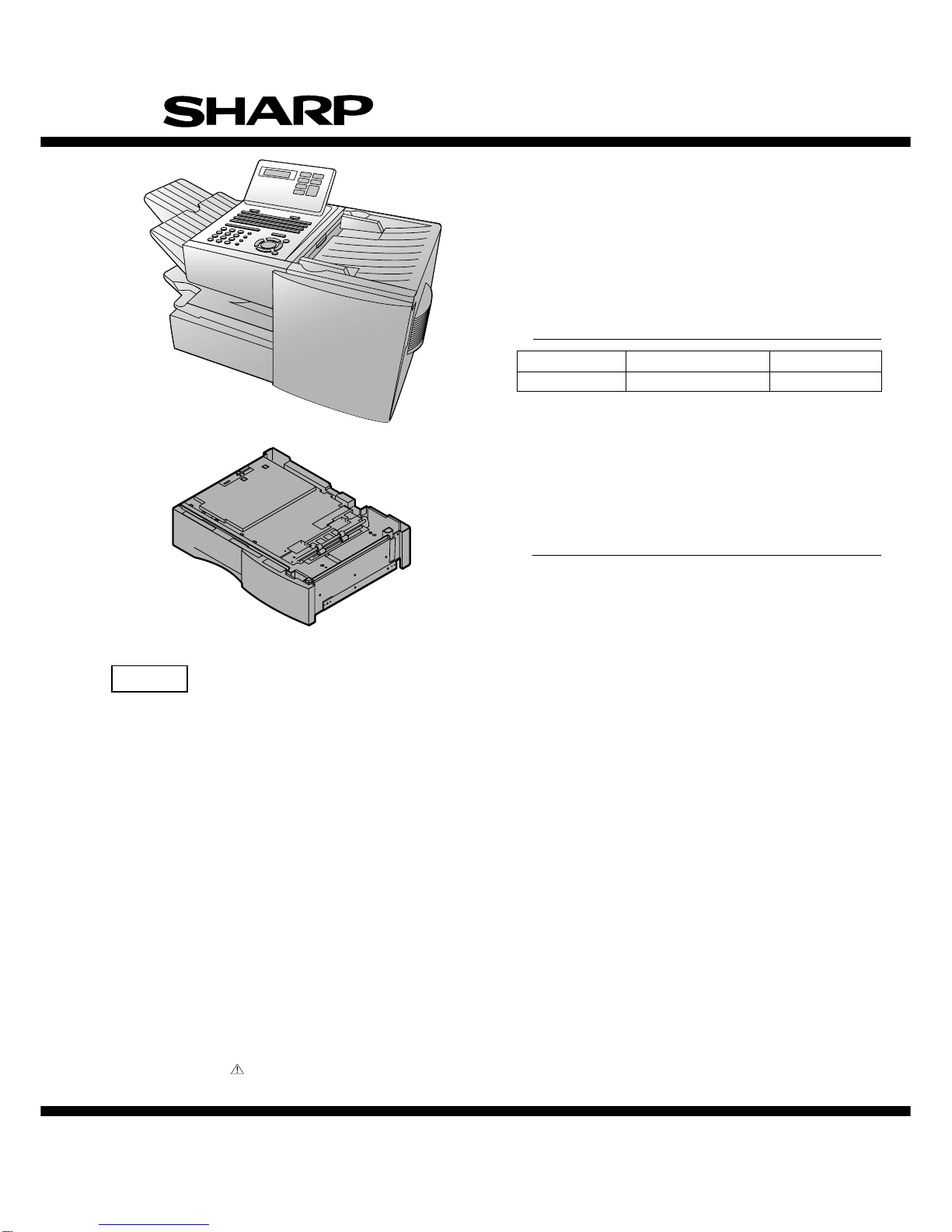
PLAIN PAPER LASER FACSIMILE
HALF TONE
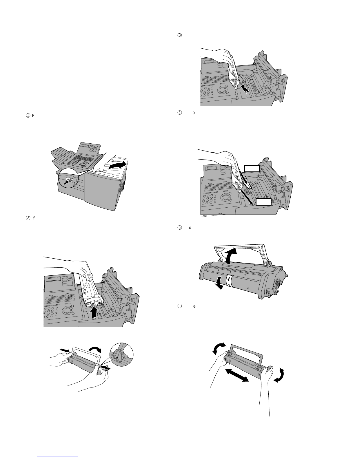
Toner Cartridge
Drum Cartridge
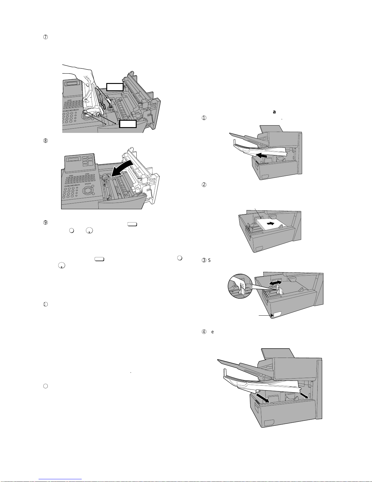
Paper Supply
Paper Jam
Paper Size Error
Printer Cover Open
Out Put Tray Error
ALARM Guide
ALARM
TONER
LINE IN USE
CONTRAST RESOLUTION
STANDARD
FINE
SUPER FINE
1
5
2 3 4
6
JKL
ABC
1
DEF
WXYZ
9
GHI
45
MNO
6
PQRS
7
TUV
8
0
2 3
OPER
PERSONAL
BOOK
SPEED DIAL
REDIAL
SPEAKER
JOB STATUS
DUPLEX SCAN
PRIORITY
BROADCAST
MENU
UP
ZA
DOWN
START/
ENTER
COPY/HELP
STOP
1717 24241818 1919 2020 2525
2626 3030 31312727 2929
2323
2828
22222121
PAGE COUNTER key
Press this key to include a slash and the total number of pages after each
page number on the pages of a transmitted document.
CONFIDENTIAL key
Press this key to send or print out a confidential document.
TIMER key
Press this key to set an operation to be performed automatically at a later
time.
11
COVER SHEET key
Press this key to include a cover sheet when sending a fax.
LIFE key
Press this key, followed by , to check the total number of pages printed
by the fax machine.
MEM. STATUS key
Press this key to check the status of fax transmission jobs, copy jobs, and
receptions.
fax This key can also be used to cancel a job.
REPORT key
Press this key to print out a report on the most recently completed
transmission or reception.
DOCUMENT key
Press this key to transmit a document directly from the feeder without
it into memory.
1
15
16
13
12
14
JOB STATUS key
Two types of information appear in the display: prompts related to
operations you are performing, and information about how the fax machine
is using the telephone line (transmitting, receiving, etc.). Press this key to
between the two types of information.
DUPLEX SCAN key
Press this key to transmit or copy a two-sided document.
PRIORITY key
Press this key when you need to transmit a document ahead of other
documents waiting in memory for transmission.
BROADCAST key
Press this key to send a fax to a group of receiving fax machines.
17
19
20
18
PERSONAL BOOK
Press this key to use or store an auto-dial number in a personal book. If
book has a passcode, enter the passcode; otherwise, select the book
with or and press .
SPEED DIAL key
Press this key to dial a Speed Dial number.
MENU key
Press this key to select special functions and settings.
UP and DOWN arrow keys
Volume setting: Press these keys to change the speaker volume when the
SPEAKER key has been pressed, or the ringer volume at any other time.
COPY/HELP key
When a document is in the feeder, press this key to make a copy of a
document. At any other time, press this key to print out the Help List, a
reference guide to the operation of your fax machine.
Dial keypad (numeric keys)
Use these keys to dial and program fax numbers.
REDIAL key
Press this key to automatically redial the lastnumber dialed.
SPEAKER key
Press this key when transmitting adocumentby NormalDialing to listen to
the line and verify the response of the receiving fax machine.
START/ENTER key
Press this key to begin fax transmission when using Speed Dialing, Direct
Keypad Dialing,or Normal Dialing. This key is also used to select settings
and complete entries when storing names and numbers.
Left and right arrow keys
Auto-dial numbers: Press these keys to search for an auto-dial number
when sending a fax.
MENU key settings: Press these keys after pressing the MENU key to
scroll through the MENU key settings.
STOP key
Press this key to cancel an operation before it is completed.
START/
ENTER
24
25
26
27
28
29
30
31
23
21
22
Display
This displays messages and prompts to help you operate the machine.
ALARM indicator
This blinks when one of the paper sources is empty or the drum cartridge is
near the end of its life (printing is still possible). This lights steadily when the
drum cartridge has reached the endof its life, all papersources areempty, the
print compartment cover is open, or a paper jam has occurred (printing is not
possible). A message will appear in the display to indicate the problem.
TONER indicator
This blinks when the toner cartridge nears empty, and lights steadily when the
toner cartridge needs replacement.
LINE IN USE light
This lights when the fax machine is using the telephone line.
CONTRAST key
Press this key to adjust the contrast before sending or copying a document.
RESOLUTION key
Press this key to adjust the resolution before sending or copying a document.
An indicator will light next to the selected setting (HALFTONE, STANDARD,
FINE or SUPER FINE).
1
2
3
4
5
6
reading
change
the
quick
9
Rapid Dial Keys
Press one of these keys to dial a fax number automatically. (Note that you
must attach the Rapid Key labels.) When navigating through the display
menu, a Rapid Key can also be pressed in place of the numeric keys to
enter a two-digit number (for example, you can press Rapid Key 01 to enter
the number “01”).
7
10
9
SYMBOL key
When entering a name, press this key to enter the symbol on a letter key
(the character to the right of the slash). Press the key again to turn off
symbol entry mode.
8