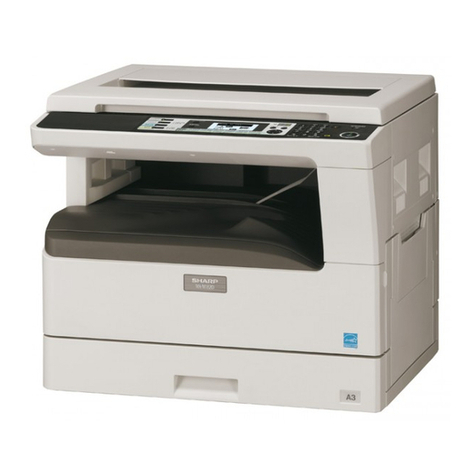
Sharp AR-235 User manual

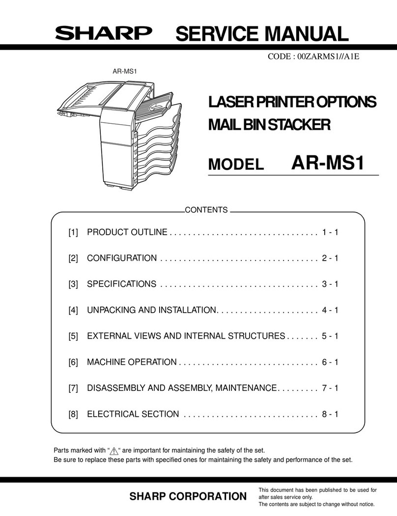
SERVICE MANUAL
CODE: 00ZAR275//A1E
DIGITAL LASER COPIER/
PRINTER
AR-235
MODEL AR-275
CONTENTS
[1] NOTE FOR SERVICING. . . . . . . . . . . . . . . . . . . . . . . . . . . . . . . . . 1-1
[2] SYSTEM CONFIGURATION . . . . . . . . . . . . . . . . . . . . . . . . . . . . . 2-1
[3] SPECIFICATIONS . . . . . . . . . . . . . . . . . . . . . . . . . . . . . . . . . . . . . 3-1
[4] CONSUMABLE PARTS . . . . . . . . . . . . . . . . . . . . . . . . . . . . . . . . . 4-1
[5] UNPACKING AND INSTALLATION . . . . . . . . . . . . . . . . . . . . . . . . 5-1
[6] EXTERNAL VIEW AND INTERNAL STRUCTURE . . . . . . . . . . . . 6-1
[7] ADJUSTMENTS, SETTING . . . . . . . . . . . . . . . . . . . . . . . . . . . . . . 7-1
[8] SIMULATION . . . . . . . . . . . . . . . . . . . . . . . . . . . . . . . . . . . . . . . . . 8-1
[9] TROUBLE CODE LIST. . . . . . . . . . . . . . . . . . . . . . . . . . . . . . . . . . 9-1
[10] DISASSEMBLY AND ASSEMBLY . . . . . . . . . . . . . . . . . . . . . . . . 10-1
[11] OTHERS. . . . . . . . . . . . . . . . . . . . . . . . . . . . . . . . . . . . . . . . . . . . 11-1
Parts marked with “ ” are important for maintaining the safety of the set. Be sure to replace these parts with
specified ones for maintaining the safety and performance of the set.
SHARP CORPORATION This document has been published to be used
for after sales service only.
The contents are subject to change without notice.

CONTENTS
[1] NOTE FOR SERVICING
1. Warning for servicing . . . . . . . . . . . . . . . . . . . . . . . . . . . . . 1-1
2. Precautions for servicing . . . . . . . . . . . . . . . . . . . . . . . . . . 1-1
3. Note for installing site. . . . . . . . . . . . . . . . . . . . . . . . . . . . . 1-1
[2] SYSTEM CONFIGURATION
1. Structure . . . . . . . . . . . . . . . . . . . . . . . . . . . . . . . . . . . . . . 2-1
A. Hardware . . . . . . . . . . . . . . . . . . . . . . . . . . . . . . . . . . . 2-1
2. System outline (Options) . . . . . . . . . . . . . . . . . . . . . . . . . . 2-2
[3] SPECIFICATIONS
1. Basic specifications . . . . . . . . . . . . . . . . . . . . . . . . . . . . . . 3-1
2. Operation specifications. . . . . . . . . . . . . . . . . . . . . . . . . . . 3-1
A. Common operation . . . . . . . . . . . . . . . . . . . . . . . . . . . . 3-1
B. Copy mode . . . . . . . . . . . . . . . . . . . . . . . . . . . . . . . . . . 3-1
3. Engine specifications . . . . . . . . . . . . . . . . . . . . . . . . . . . . . 3-2
A. Operation and display section . . . . . . . . . . . . . . . . . . . 3-2
B. Paper feed, transport, paper exit section . . . . . . . . . . . 3-2
C. Optical (Image scanning) section . . . . . . . . . . . . . . . . . 3-3
D. Scanner (exposure) section . . . . . . . . . . . . . . . . . . . . . 3-3
E. Image process section . . . . . . . . . . . . . . . . . . . . . . . . . 3-3
F. Fusing. . . . . . . . . . . . . . . . . . . . . . . . . . . . . . . . . . . . . . 3-4
G. DRIVE. . . . . . . . . . . . . . . . . . . . . . . . . . . . . . . . . . . . . . 3-4
4. Safety and environmental protection standards. . . . . . . . . 3-4
5. Environment conditions . . . . . . . . . . . . . . . . . . . . . . . . . . . 3-4
[4] CONSUMABLE PARTS
1. List . . . . . . . . . . . . . . . . . . . . . . . . . . . . . . . . . . . . . . . . . . . 4-1
A. SEC/LAG . . . . . . . . . . . . . . . . . . . . . . . . . . . . . . . . . . . 4-1
B. SECL . . . . . . . . . . . . . . . . . . . . . . . . . . . . . . . . . . . . . . 4-2
C. Europe affiliates/East Europe/SEEG/SUK/SCA/
SCNZ/SEA/SEES/SEZ/SEIS/SEB/SEN/SEF/SMEF/
Russia/Middle East/Africa/CIS . . . . . . . . . . . . . . . . . . . 4-3
D. Special country/Taiwan . . . . . . . . . . . . . . . . . . . . . . . . . 4-4
E. Asia affiliates /Asia agent/STCL/SRH/SRS/SRSSC/
SBI . . . . . . . . . . . . . . . . . . . . . . . . . . . . . . . . . . . . . . . . 4-5
2. Production number identification . . . . . . . . . . . . . . . . . . . . 4-6
3. Environment conditions . . . . . . . . . . . . . . . . . . . . . . . . . . . 4-6
A. Ambient conditions for transporting . . . . . . . . . . . . . . . 4-6
B. Ambient storage conditions (sealed) . . . . . . . . . . . . . . 4-6
C. Operating ambient conditions. . . . . . . . . . . . . . . . . . . . 4-6
4. Life (packed conditions) . . . . . . . . . . . . . . . . . . . . . . . . . . . 4-6
[5] UNPACKING AND INSTALLATION
1. Removal of protective material and fixing screw . . . . . . . . 5-1
2. Removal and storage of fixing pin . . . . . . . . . . . . . . . . . . . 5-1
3. Developer cartridge installation . . . . . . . . . . . . . . . . . . . . . 5-1
4. Toner cartridge installation . . . . . . . . . . . . . . . . . . . . . . . . . 5-2
5. Toner concentration sensor level adjustment. . . . . . . . . . . 5-2
6. Paper size selection for paper feed tray . . . . . . . . . . . . . . 5-2
[6] EXTERNAL VIEW AND INTERNAL STRUCTURE
1. External view . . . . . . . . . . . . . . . . . . . . . . . . . . . . . . . . . . . 6-1
2. Internal . . . . . . . . . . . . . . . . . . . . . . . . . . . . . . . . . . . . . . . . 6-1
3. Operation panel . . . . . . . . . . . . . . . . . . . . . . . . . . . . . . . . .6-2
A. Key position . . . . . . . . . . . . . . . . . . . . . . . . . . . . . . . . . .6-2
B. LCD panel . . . . . . . . . . . . . . . . . . . . . . . . . . . . . . . . . . .6-2
4. Motor, Solenoid, Clutch . . . . . . . . . . . . . . . . . . . . . . . . . . . .6-3
5. Sensor. . . . . . . . . . . . . . . . . . . . . . . . . . . . . . . . . . . . . . . . .6-3
6. PWB unit . . . . . . . . . . . . . . . . . . . . . . . . . . . . . . . . . . . . . . .6-4
7. Section . . . . . . . . . . . . . . . . . . . . . . . . . . . . . . . . . . . . . . . .6-4
[7] ADJUSTMENTS, SETTING
1. List of adjustment items . . . . . . . . . . . . . . . . . . . . . . . . . . .7-1
2. Copier adjustment. . . . . . . . . . . . . . . . . . . . . . . . . . . . . . . .7-1
A. Process section . . . . . . . . . . . . . . . . . . . . . . . . . . . . . . .7-1
B. Mechanism section . . . . . . . . . . . . . . . . . . . . . . . . . . . .7-2
C. Image density (exposure) adjustment . . . . . . . . . . . . . .7-9
[8] SIMULATION
1. Operating procedures and operations . . . . . . . . . . . . . . . .8-1
A. Basic operation . . . . . . . . . . . . . . . . . . . . . . . . . . . . . . .8-1
B. Simulation kinds and valid key functions . . . . . . . . . . . .8-1
C. Simulation operation and procedure basic pattern . . . .8-2
2. Simulation code list . . . . . . . . . . . . . . . . . . . . . . . . . . . . . . .8-3
3. Details . . . . . . . . . . . . . . . . . . . . . . . . . . . . . . . . . . . . . . . . .8-5
[9] TROUBLE CODE LIST
1. List . . . . . . . . . . . . . . . . . . . . . . . . . . . . . . . . . . . . . . . . . . .9-1
2. Self diagnostics . . . . . . . . . . . . . . . . . . . . . . . . . . . . . . . . . .9-1
[10] DISASSEMBLY, ASSEMBLY AND MAINTENANCE
1. Maintenance table. . . . . . . . . . . . . . . . . . . . . . . . . . . . . . .10-1
2. Counter clear . . . . . . . . . . . . . . . . . . . . . . . . . . . . . . . . . .10-1
3. List of disassembly and assembly . . . . . . . . . . . . . . . . . .10-1
4. Details . . . . . . . . . . . . . . . . . . . . . . . . . . . . . . . . . . . . . . . .10-2
A. Process unit. . . . . . . . . . . . . . . . . . . . . . . . . . . . . . . . .10-2
B. Developing section . . . . . . . . . . . . . . . . . . . . . . . . . . .10-3
C. Fusing section . . . . . . . . . . . . . . . . . . . . . . . . . . . . . . .10-4
D. Paper feed section. . . . . . . . . . . . . . . . . . . . . . . . . . . .10-6
E. Side door unit . . . . . . . . . . . . . . . . . . . . . . . . . . . . . .10-10
F. 1st paper exit unit . . . . . . . . . . . . . . . . . . . . . . . . . . .10-10
G. Laser unit. . . . . . . . . . . . . . . . . . . . . . . . . . . . . . . . . .10-12
H. Power unit . . . . . . . . . . . . . . . . . . . . . . . . . . . . . . . . .10-13
I. PWB . . . . . . . . . . . . . . . . . . . . . . . . . . . . . . . . . . . . .10-13
J. Ozone filter . . . . . . . . . . . . . . . . . . . . . . . . . . . . . . . .10-15
[11] OTHERS
1. Flash ROM version up procedure . . . . . . . . . . . . . . . . . . .11-1
A. Program download procedure
(Main body program, FAX program) . . . . . . . . . . . . . .11-1
2. User programs . . . . . . . . . . . . . . . . . . . . . . . . . . . . . . . . .11-2
3. E-MAIL STATUS/E-MAIL ALERTS . . . . . . . . . . . . . . . . . .11-3
A. Basic functions . . . . . . . . . . . . . . . . . . . . . . . . . . . . . .11-3
B. Main body specifications . . . . . . . . . . . . . . . . . . . . . . .11-3
C. Printer controller specifications . . . . . . . . . . . . . . . . . .11-3
D. Handling of transmission data . . . . . . . . . . . . . . . . . . .11-3
CONTENTS
PARTS GUIDE
CODE:00ZAR275//P1E
Digital Laser Copier/Printer
AR-275
MODEL AR-235
1Exteriors 1
2Exteriors 2
3Delivery tray section
4OC cover unit(Option AR-VR3)
5Operation panel unit
6Frame section
7Lump unit
8Optical frame 1
9Optical frame 2
FMiddle frame
G550 cassette unit
HPaper feed section
IPaper transfer section
JSide door unit
KTC unit
LMulti manual paper feed tray unit
MMulti manual paper feed unit
NDV unit
OProcess unit
PFusing unit 1
QFusing unit 2
RDrive unit
S1st delivery paper unit 1
T1st delivery paper unit 2
U2nd delivery paper unit
VPWB section
WRear frame section
X2nd exteiors
Y2nd 550 cassette unit
Z2nd paper feed section
[2nd paper transfer section
\2nd drive section
]Pick up motor unit
^Job seprator unit(Option AR-TR3)
_Packing material & accessories
.MCU PWB
aIMC PWB
bLCD backlight PWB
cKEY/LED R PWB
dKEY/LED L PWB
eOption connector PWB
f2nd Interface PWB
■Index
SHARP CORPORATION This document has been published to be
used for after sales service only.
The contents are subject to change without
notice.

DEFINITION
The definition of each Rank is as follows and also noted in the list
A : Parts necessary to be stocked as High usage parts.
B : Parts necessary to be stocked as Standard usage parts.
C : Low usage parts.
D : Parts necessary for refurbish.
E : Unit parts recommended to be stocked for efficient after sales service.
Please note that the lead time for the said parts may be longer than normal parts.
S : Consumable parts.
Please note that the following parts used in Copier under the same description are classified into A or B Rank depending
upon the place used.
Example: Gear made of Metal, Sprocket, Bearing, Belt made of Rubber, Spring clutch mechanism.
A Rank : The parts which may be with the revolution or loading.
B Rank : Parts similar to A Rank parts, but are not included in Rank A.
Because parts marked with "!" is indispensable for the machine safety maintenance and operation, it must be replaced with
the parts specific to the product specification.
FOther than this Parts Guide, please refer to documents Service Manual (including Circuit Diagram) of this model.
FPlease use the 13 digit code described in the right hand corner of front cover of the document, when you place an order.
FFor U.S. only-Use order codes provided in advertising literature. Do not order from parts department.
1 Exteriors 1
NO. PARTS CODE PRICE
RANK NEW
MARK PART
RANK DESCRIPTION
1GCAB-0035QSZZ AK N D Op ical left cabinet upper
2GCAB-0036QSZZ AH N D Op ical left cabinet lower
3CFIX-0013QS01 AK N D Glass fixing plate
4PSHEZ0220QSZ1 AK N C Shadhing sheet
5LX-BZ0024QSZZ AA NCScrew
6GCAB-0040QSZZ AX N D Rear cabinet upper
7CGIDM0077QS01 AL N C OR guide
8LFIX-0011QSZZ AK N D OC glass fixing plate
9GCAB-0033QSZZ AK N D Op ical right cabinet upper
10 GCAB-0034QSZZ AK N D Op ical right cabinet lower
11 PGLSP0003QSZZ BA B Table glass
12 GCAB-0031QSZZ AS N D Op ical front cabinet upper
13 GCAB-0032QSZZ AQ N D Op ical front cabinet lower
14 CPNLH0020QS01 AK N C Model panel (AR-235)
CPNLH0020QS02 AK N C Model panel (AR-275)
15 TLABH0302QSZZ AG C Opera ion label
1 Exteriors 1
2 Exteriors 2
NO. PARTS CODE PRICE
RANK NEW
MARK PART
RANK DESCRIPTION
1GCAB-0042QSZZ AP N D Rear cabinet left
2GCOV-0028QSZZ BA N D Power supply cover
3XHBSE30P08000 AA CScrew(3×8)
4GCOV-0029QSZZ AR N D Delivery rear cover upper
5GCOV-0030QSZZ AT N D Delivery rear cover lower
6GCAB-0043QSZZ AN N D Rear cabinet lower
7XEBSE40P10000 AA CScrew(4×10)
8GCAB-0041QSZZ BA N D Rear cabinet right
9GCOV-0034QSZZ AK N D Rear cabinet memory cover
10 GCOV-0031QSZZ AK N D Delivery dummy cover
1
23
5
5
5
5
5
6
7
8
5
5
59
10
12
11
13
14
4
FCP04715
15
– 1 –

2 Exteriors 2
NO. PARTS CODE PRICE
RANK NEW
MARK PART
RANK DESCRIPTION
11 MSPRD0189QSZZ AB N C Right cabinet spring
12 MLEVP0069QSZZ AD N C Right cabinet lever
13 GDOR-0003QSZ1 AP N D Right cabinet door
14 NROLP1060FCZZ AF C U-turn roller
15 MSPRT0229GCAZ AC C FU spring R
16 GCAB-0039QSZZ AR N D Right cabinet
17 GCOV-0043QSZ1 AS N D OP PWB cover
18 PFILZ0011QSZZ AS N C Ozon filter
23 GCAB-0037QSZZ AL N D Front right cabinet (U.S A)
CCAB-0037QS01 AN N D Front right cabinet Except(U.S.A)
24 LSOU-0033QSZZ AR N D Delivery exetension tray
25
CPNLH0016QS51 BD N E Opera ion panel unit (U.S.A,U.Kingdom,Australia,New Zealand,Philippines)
CPNLH0016QS53 CA N E Opera ion panel unit (Canada)
CPNLH0016QS55 CB NE
Opera ion panel unit (Germany,Greece,Cyprus,Turkey,
Poland,Hungary,Czechoslovakia,LAG2,LAG4)
CPNLH0016QS56 CB N E Opera ion panel unit (Sweden,Finland,Norway,Denmark)
CPNLH0016QS54 CA N E Opera ion panel unit (Other countries)
26 GCAB-0038QSZZ AX N D Front cabinet
27 GCOV-0032QSZZ AE N D Power supply switch cover (120V)
GCOV-0032QSZ1 AE N D Power supply switch cover (O her countries)
28 CARMM0023QS01 AD N C Hinge arm R
29 MARMM0022QSZZ AC N C Hinge arm L
30 LPIN-0277FCZZ AB C Slide pin
31 CCOV-0027QS01 AU N D Front cover (U.S A)
GCOV-0027QSZZ AT N D Front cover (Except U.S.A)
32 DHAI-0205QSZZ AG N C Opara ion unit harness
33 XEBSE30P08000 AA CScrew(3×8)
34 XEBSE40P12000 AA CScrew(4×12)
35 XHBSE40P10000 AA CScrew(4×10)
36 XHBSE40P18000 AB N C Screw (4×18)
37 LX-BZ0024QSZZ AA NCScrew
38 GCOV-0042QSZZ AK N C Rail dummy cover
40 TLABZ0058QSZZ AD C Class 1 label [Except U.S.A,Canada,Taiwan,LAG2,Brazil]
41 TLABH0264GCZZ AC C Service man label [Europe]
42 TCAUA0770FCZZ AB C Service caution card
43 TLABH0360QSZZ AD N C Power supply label (120V)
44 TLABH0361QSZZ AD N C Warm heater label (120V)
45 PSHEZ0281QSZZ AC N C Damper sheet C
46 PSHEZ0280QSZZ AE N C Damper sheet B
47 PMLT-0057QSZZ AC N C Front cabinet cushion
48 PMLT-0059QSZZ AC N C Front cabinet cushion C
49 PMLT-0046QSZZ AF N C Front cabinet cushion under
50 PMLT-0062QSZZ AD N C Delivery rear cover upper cushion B
51 LPLTM0263QSZZ AP N C Reinforce plate C
52 PMLT-0048QSZZ AF N C Power supply cover cushion F
53 PMLT-0047QSZZ AK N C Power supply cover cushion UP
54 PMLT-0050QSZZ AC N C Power supply cover cushion L corner B
55 PMLT-0051QSZZ AF N C Power supply cover left cushion A
56 PMLT-0052QSZZ AD N C Power supply cover left cushion B
57 PMLT-0065QSZZ AD N C Rail dummy cover cushion
2 Exteriors 2
53
54
43
44
13
2
3
71737
7
77
9
3
4
5
3
33
12
11
15
1413
16
7
10
23
24
37
25
32
33
33
27
26
34
30
29
36
31
35 28
3
7
3
15
14
35
8
6
FCP04716
38
37
40
41
42
18
46
45
45
57
52
50
5655 54
5450
49
51
47
48
– 2 –
Other manuals for AR-235
2
This manual suits for next models
1
Table of contents
Other Sharp Printer manuals

Sharp
Sharp MZ-1P16 User manual

Sharp
Sharp AR-M280 User manual

Sharp
Sharp AJ-2200 Setup guide

Sharp
Sharp AR-200M User manual

Sharp
Sharp CS-2635RH User manual

Sharp
Sharp JX-8200 User manual

Sharp
Sharp MX-C300PE Guide

Sharp
Sharp MX-C400P User manual

Sharp
Sharp AR-M450 Imager User manual

Sharp
Sharp JX-735 User manual

Sharp
Sharp AJ-2000 Setup guide

Sharp
Sharp MX-B400P Installation and operating manual

Sharp
Sharp MX-C400P User manual

Sharp
Sharp MX-2301N User manual

Sharp
Sharp SF-7200 User manual

Sharp
Sharp MX-FR44U User manual

Sharp
Sharp JX-9300 User manual

Sharp
Sharp JX-8200 User manual

Sharp
Sharp BP-1200S User guide

Sharp
Sharp AR-M550N Service manual