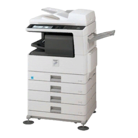
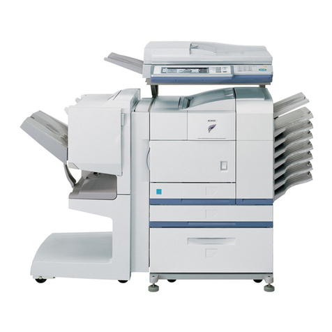
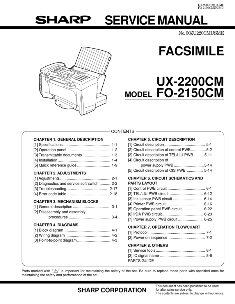
Sharp SF-2014 User manual

SERVICE MANUAL
CODE: 00ZSF2214SMRE
MODEL SF-2014
MODEL SF-2114
MODEL SF-2214
Options •Paper tray (SF-UB14)
•Multi paper feed unit (SF-MF14)
•Paper feed unit (SF-CM14)
•Copier table (SF-720D2)
•Personal counter (SF-71A/71B)
[ 1 ] GENERAL DESCRIPTION . . . . . . . . . . . . . . . . . . . . . . . . . . . . . . . . . . . . . . . . . . 1-1
[ 2 ] PRODUCT SPECIFICATIONS . . . . . . . . . . . . . . . . . . . . . . . . . . . . . . . . . . . . . . . 2-1
[ 3 ] EXTERNAL VIEW AND INTERNAL STRUCTURE . . . . . . . . . . . . . . . . . . . . . . . 3-1
[ 4 ] UNPACKING AND INSTALLATION . . . . . . . . . . . . . . . . . . . . . . . . . . . . . . . . . . 4-1
[ 5 ] GENERAL DESCRIPTIONS OF EACH SECTION . . . . . . . . . . . . . . . . . . . . . . . 5-1
[ 6 ] DISASSEMBLY AND ASSEMBLY . . . . . . . . . . . . . . . . . . . . . . . . . . . . . . . . . . . 6-1
[ 7 ] ADJUSTMENTS . . . . . . . . . . . . . . . . . . . . . . . . . . . . . . . . . . . . . . . . . . . . . . . . . . 7-1
[ 8 ] SIMULATIONS . . . . . . . . . . . . . . . . . . . . . . . . . . . . . . . . . . . . . . . . . . . . . . . . . . . 8-1
[ 9 ] SELF DIAGNOSTICS . . . . . . . . . . . . . . . . . . . . . . . . . . . . . . . . . . . . . . . . . . . . . 9-1
[10] SERVICE AT MEMORY TROUBLE AND
[10] MAIN CONTROL PWB REPLACEMENT . . . . . . . . . . . . . . . . . . . . . . . . . . . . .10-1
[11] MAINTENANCE . . . . . . . . . . . . . . . . . . . . . . . . . . . . . . . . . . . . . . . . . . . . . . . . .11-1
[12] ELECTRICAL SECTION . . . . . . . . . . . . . . . . . . . . . . . . . . . . . . . . . . . . . . . . . .12-1
SHARP CORPORATION
CONTENTS
This document has been published to be used
for after sales service only.
The contents are subject to change without notice.
Parts marked with "!" is important for maintaining the safety of the set. Be sure to replace these parts with specified
ones for maintaining the safety and performance of the set.
SF-2014
SF-2114
SF-2214

CONTENTS
[ 1 ] GENERAL DESCRIPTION . . . . . . . . . . . . . . . . . . . 1-1
1. Features . . . . . . . . . . . . . . . . . . . . . . . . . . . . . . . . . . . . 1-1
2. Target users . . . . . . . . . . . . . . . . . . . . . . . . . . . . . . . . . 1-1
3. Novel technology . . . . . . . . . . . . . . . . . . . . . . . . . . . . . . 1-1
4. Novel functions . . . . . . . . . . . . . . . . . . . . . . . . . . . . . . . 1-1
[ 2 ] PRODUCT SPECIFICATIONS . . . . . . . . . . . . . . . 2-1
1. Basic specifications . . . . . . . . . . . . . . . . . . . . . . . . . . . 2-1
2. Details of each section . . . . . . . . . . . . . . . . . . . . . . . . . 2-2
3. Supplies . . . . . . . . . . . . . . . . . . . . . . . . . . . . . . . . . . . . 2-3
[ 3 ] EXTERNAL VIEW AND INTERNAL
STRUCTURE . . . . . . . . . . . . . . . . . . . . . . . . . . . . . . . 3-1
1. External view and internal structure
(SF-2214 as the example model) . . . . . . . . . . . . . . . . . 3-1
2. Operation panel . . . . . . . . . . . . . . . . . . . . . . . . . . . . . . . 3-2
3. Cross section (SF-2214 as the example model) . . . . . . 3-3
4. Switches, sensors, detectors
(The SF-2214 as the typical example) . . . . . . . . . . . . . 3-4
5. Clutches, solenoids
(The SF-2214 as the typical example) . . . . . . . . . . . . . 3-5
6. Motors (The SF-2214 as the typical example) . . . . . . . 3-6
7. PWBs (The SF-2214 as the typical example) . . . . . . . . 3-7
[ 4 ] UNPACKING AND INSTALLATION . . . . . . . . . 4-1
1. Packing drawing . . . . . . . . . . . . . . . . . . . . . . . . . . . . . . 4-1
2. Installation . . . . . . . . . . . . . . . . . . . . . . . . . . . . . . . . . . 4-1
(1) Environment . . . . . . . . . . . . . . . . . . . . . . . . . . . . . . . 4-1
(2) Space around the machine . . . . . . . . . . . . . . . . . . . 4-2
(3) Installing table . . . . . . . . . . . . . . . . . . . . . . . . . . . . . 4-2
(4) Power source . . . . . . . . . . . . . . . . . . . . . . . . . . . . . . 4-3
(5) Grounding . . . . . . . . . . . . . . . . . . . . . . . . . . . . . . . . 4-3
3. Installation procedure . . . . . . . . . . . . . . . . . . . . . . . . . . 4-3
(1) Optical system unlocking . . . . . . . . . . . . . . . . . . . . . 4-3
(2) Cassette setting . . . . . . . . . . . . . . . . . . . . . . . . . . . . 4-3
(3) Developer setting . . . . . . . . . . . . . . . . . . . . . . . . . . . 4-4
(4) Toner supply . . . . . . . . . . . . . . . . . . . . . . . . . . . . . . 4-4
(5) Toner density sensor level check . . . . . . . . . . . . . . 4-5
(6) Accessory attachment . . . . . . . . . . . . . . . . . . . . . . . 4-5
4. Locking procedure for transit or repacking
(1) No.2/No.3 mirror unit (Mirror base B) lock . . . . . . . 4-5
(2) No.4/no.5 mirror unit (Mirror base C) lock . . . . . . . 4-6
[ 5 ] GENERAL DESCRIPTIONS OF
EACH SECTION . . . . . . . . . . . . . . . . . . . . . . . . . . . . 5-1
1. Paper feed section . . . . . . . . . . . . . . . . . . . . . . . . . . . . 5-1
2. Separation, transport section . . . . . . . . . . . . . . . . . . . . 5-2
3. Fuser, paper exit section . . . . . . . . . . . . . . . . . . . . . . . 5-2
4. Developer section . . . . . . . . . . . . . . . . . . . . . . . . . . . . 5-2
5. Optical system . . . . . . . . . . . . . . . . . . . . . . . . . . . . . . . . 1-3
5-1. General descriptions . . . . . . . . . . . . . . . . . . . . . . . 5-3
(1) Original table . . . . . . . . . . . . . . . . . . . . . . . . 5-3
(2) Copy lamp . . . . . . . . . . . . . . . . . . . . . . . . . . 5-3
(3) Mirror . . . . . . . . . . . . . . . . . . . . . . . . . . . . . . 5-3
(4) Lens (Fixed focus lens) . . . . . . . . . . . . . . . . . 5-3
(5) Lens home position sensor (LHPS) . . . . . . . 5-3
(6) Lens base . . . . . . . . . . . . . . . . . . . . . . . . . . . 5-3
(7) Lens drive shaft . . . . . . . . . . . . . . . . . . . . . . .5-4
(8) Lens drive wire . . . . . . . . . . . . . . . . . . . . . . . .5-4
(9) No. 4/5 mirror base . . . . . . . . . . . . . . . . . . . .5-4
(10) Mirror motor . . . . . . . . . . . . . . . . . . . . . . . . . .5-4
(11) Mirror home position sensor (MHPS) . . . . . . .5-4
(12) No. 2/3 mirror base . . . . . . . . . . . . . . . . . . . .5-4
(13) Copy lamp unit . . . . . . . . . . . . . . . . . . . . . . .5-4
(14) Thermal fuse . . . . . . . . . . . . . . . . . . . . . . . . .5-4
(15) Reflector . . . . . . . . . . . . . . . . . . . . . . . . . . . . .5-4
(16) Exposure adjustment plates . . . . . . . . . . . . . .5-4
(17) Mirror base drive wire . . . . . . . . . . . . . . . . . . .5-4
(18) Lens drive motor . . . . . . . . . . . . . . . . . . . . . .5-4
(19) AE sensor . . . . . . . . . . . . . . . . . . . . . . . . . . . .5-4
5-2. Basic operations . . . . . . . . . . . . . . . . . . . . . . . . . . .5-4
6. Copy process . . . . . . . . . . . . . . . . . . . . . . . . . . . . . . . . .5-6
(1) Photoconductor . . . . . . . . . . . . . . . . . . . . . . . . . . .5-6
(2) Process diagram . . . . . . . . . . . . . . . . . . . . . . . . . . .5-6
(3) Actual process . . . . . . . . . . . . . . . . . . . . . . . . . . . .5-7
(4) Transit of photoconductor drum surface
potential . . . . . . . . . . . . . . . . . . . . . . . . . . . . . . . .5-11
(5) Process correction system . . . . . . . . . . . . . . . . . .5-12
1) Outline of the correction system . . . . . . . . . . .5-12
2) Correction operation . . . . . . . . . . . . . . . . . . . .5-12
7. SPF section (SF-2214 only) . . . . . . . . . . . . . . . . . . . . .5-14
1. Outline . . . . . . . . . . . . . . . . . . . . . . . . . . . . . . . . . . .5-14
[ 6 ] DISASSEMBLY AND ASSEMBLY . . . . . . . . . . . 6-1
1. Paper feed section, paper transport section,
power section . . . . . . . . . . . . . . . . . . . . . . . . . . . . . . . . .6-1
1-1. Paper feed unit . . . . . . . . . . . . . . . . . . . . . . . . . . .6-1
1-2. Paper feed roller ass’y removal . . . . . . . . . . . . . .6-1
1-3. Separation roller . . . . . . . . . . . . . . . . . . . . . . . . .6-2
1-4. Takeup roller, paper feed roller . . . . . . . . . . . . . .6-2
1-6. Transport belt . . . . . . . . . . . . . . . . . . . . . . . . . . . .6-4
1-7. Socket holder unit . . . . . . . . . . . . . . . . . . . . . . . . .6-4
1-8. Lower unit PWB . . . . . . . . . . . . . . . . . . . . . . . . . .6-4
1-9. Cassette paper empty detector (CPED1) . . . . . . .6-4
1-10. Power unit . . . . . . . . . . . . . . . . . . . . . . . . . . . . . . .6-4
2. Manual paper feed section . . . . . . . . . . . . . . . . . . . . . . .6-5
2-1. Manual paper feed roller, manual takeup roller . . .6-5
2-2. Reverse rotation roller ass’y . . . . . . . . . . . . . . . . . .6-5
3. Fuser section . . . . . . . . . . . . . . . . . . . . . . . . . . . . . . . . .6-6
3-1. Fuser unit removal . . . . . . . . . . . . . . . . . . . . . . . . .6-6
3-2. Heater lamp replacement . . . . . . . . . . . . . . . . . . . .6-6
3-3. Upper heat roller ass’y removal . . . . . . . . . . . . . . .6-7
3-4. Upper separation pawl replacement . . . . . . . . . . . .6-7
3-6. Scraper replacement . . . . . . . . . . . . . . . . . . . . . . .6-8
3-7. Thermistor/thermostat removal . . . . . . . . . . . . . . . .6-8
3-8. Heat roller/heater lamp removal . . . . . . . . . . . . . .6-8
4. Optical system . . . . . . . . . . . . . . . . . . . . . . . . . . . . . . . .6-9
4-1. Copy lamp replacement . . . . . . . . . . . . . . . . . . . . .6-9
4-2. Copy lamp unit replacement . . . . . . . . . . . . . . . . . .6-9
4-3. Mirror base drive wire replacement . . . . . . . . . . . .6-9
4-6. Optical unit removal . . . . . . . . . . . . . . . . . . . . . . .6-11
4-7. Other parts in the optical system . . . . . . . . . . . . .6-11
4-8. Light adjustment plate/temperature fuse
removal . . . . . . . . . . . . . . . . . . . . . . . . . . . . . . . .6-12
5. SPF section . . . . . . . . . . . . . . . . . . . . . . . . . . . . . . . . .6-13
5-1. SPF mechanism removal . . . . . . . . . . . . . . . . . . .6-13
I

5-2. Paper feed roller/takeup roller replacement . . . . 6-14
5-3. Reverse roller (ass’y) replacement . . . . . . . . . . . 6-14
5-4. SPF control PWB replacement . . . . . . . . . . . . . . 6-15
5-5. Clutch/solenoid removal . . . . . . . . . . . . . . . . . . . 6-15
5-6. Sensor removal . . . . . . . . . . . . . . . . . . . . . . . . . 6-15
6. Drum section . . . . . . . . . . . . . . . . . . . . . . . . . . . . . . . 6-16
6-1. Drum unit removal . . . . . . . . . . . . . . . . . . . . . . . . 6-16
7. Developer section . . . . . . . . . . . . . . . . . . . . . . . . . . . 6-16
7-1. Developer unit removal . . . . . . . . . . . . . . . . . . . . 6-16
7-2. Developer cartridge removal . . . . . . . . . . . . . . . 6-16
7-3. Toner motor removal . . . . . . . . . . . . . . . . . . . . . 6-17
7-4. Toner density sensor . . . . . . . . . . . . . . . . . . . . . 6-17
8. Operation panel section/medium cabinet . . . . . . . . . . 6-17
9. Major parts in the frame side . . . . . . . . . . . . . . . . . . . . 6-18
9-1. Ozone filter . . . . . . . . . . . . . . . . . . . . . . . . . . . . . 6-18
9-2. Optical unit/SPF unit cooling fan removal . . . . . . 6-18
9-3. Ventilation fan motor . . . . . . . . . . . . . . . . . . . . . 6-18
9-4. Transport roller clutch . . . . . . . . . . . . . . . . . . . . 6-19
9-5. Paper exit sensor . . . . . . . . . . . . . . . . . . . . . . . . 6-19
[ 7 ] ADJUSTMENTS . . . . . . . . . . . . . . . . . . . . . . . . . . . . . 7-1
1. Developer section . . . . . . . . . . . . . . . . . . . . . . . . . . . . 7-1
(1) MG roller main pole position adjustment . . . . . . . . . 7-1
(2) Adjustment of clearance between DV doctor and MG
roller . . . . . . . . . . . . . . . . . . . . . . . . . . . . . . . . . . . . . 7-2
2. Optical section . . . . . . . . . . . . . . . . . . . . . . . . . . . . . . . . 7-3
A. Adjustments list . . . . . . . . . . . . . . . . . . . . . . . . . . . . 7-3
B. Notes . . . . . . . . . . . . . . . . . . . . . . . . . . . . . . . . . . . . 7-3
C. Adjustment contents . . . . . . . . . . . . . . . . . . . . . . . . 7-6
(1) Lens . . . . . . . . . . . . . . . . . . . . . . . . . . . . . . . . . . 7-6
(2) Mirror . . . . . . . . . . . . . . . . . . . . . . . . . . . . . . . . 7-7
(3) Image distortion adjustment . . . . . . . . . . . . . . . 7-8
(4) Copy image center position adjustment . . . . . 7-12
(5) Focus adjustment (Resolution adjustment) . . . 7-13
(6) Copy magnification ratio adjustment . . . . . . . . 7-14
(7) Uniformity adjustment . . . . . . . . . . . . . . . . . . . 7-17
(8) Image loss/void area adjustment . . . . . . . . . . . 7-18
3. COPY DENSITY ADJUSTMENT . . . . . . . . . . . . . . . . 7-24
(1) Copy density adjustment timing . . . . . . . . . . . . . 7-24
(2) Note for copy density adjustment . . . . . . . . . . . . 7-24
(3) Necessary items for the copy density adjustment 7-24
(4) Copy density adjustment mode . . . . . . . . . . . . . . 7-24
(5) Copy density adjustment procedure . . . . . . . . . . 7-24
A. Test chart (UK0G-0162FCZZ) setting . . . . . . 7-24
B. Normal copy mode (Non-toner-save mode)
copy density adjustment . . . . . . . . . . . . . . . . 7-24
C. Normal copy mode (Toner save mode)
copy density adjustment . . . . . . . . . . . . . . . . 7-25
D. Photo copy mode (Non-toner-save mode)
copy density adjustment . . . . . . . . . . . . . . . . 7-25
E. Auto copy mode (Non-toner-save mode)
copy density adjustment . . . . . . . . . . . . . . . . 7-25
F. Auto copy mode (Toner save mode) copy
density adjustment . . . . . . . . . . . . . . . . . . . . . 7-26
(6) Copy density adjustment table . . . . . . . . . . . . . . 7-27
4. Others . . . . . . . . . . . . . . . . . . . . . . . . . . . . . . . . . . . . . 7-28
(1) Transfer charger wire installation . . . . . . . . . . . . 7-28
(2) DV bias adjustment . . . . . . . . . . . . . . . . . . . . . . . 7-28
(3) Separation charger output adjustment . . . . . . . . 7-28
[ 8 ] SIMULATIONS . . . . . . . . . . . . . . . . . . . . . . . . . . . . . . 8-1
1. Outline . . . . . . . . . . . . . . . . . . . . . . . . . . . . . . . . . . . . . .8-1
2. Purpose . . . . . . . . . . . . . . . . . . . . . . . . . . . . . . . . . . . . .8-1
3. Operating procedure . . . . . . . . . . . . . . . . . . . . . . . . . . . .8-1
4. Purpose list . . . . . . . . . . . . . . . . . . . . . . . . . . . . . . . . . . .8-2
5. Details of simulations . . . . . . . . . . . . . . . . . . . . . . . . . . .8-3
6. User simulations . . . . . . . . . . . . . . . . . . . . . . . . . . . . . .8-13
[ 9 ] SELF DIAG . . . . . . . . . . . . . . . . . . . . . . . . . . . . . . . . . .9-1
1. Summary/purpose . . . . . . . . . . . . . . . . . . . . . . . . . . . . .9-1
2. Operation . . . . . . . . . . . . . . . . . . . . . . . . . . . . . . . . . . . .9-1
3. Clearing the self diag display . . . . . . . . . . . . . . . . . . . . .9-1
4. Self diag contents . . . . . . . . . . . . . . . . . . . . . . . . . . . . . .9-2
5. Conditions for the JAM display . . . . . . . . . . . . . . . . . . . .9-7
1) Paper feed section . . . . . . . . . . . . . . . . . . . . . . . . . .9-7
2) Transport section . . . . . . . . . . . . . . . . . . . . . . . . . . .9-7
[10] SERVICING AT MEMORY TROUBLE AND
MAIN CONTROL PWB REPLACEMENT . . . .10-1
1. General . . . . . . . . . . . . . . . . . . . . . . . . . . . . . . . . . . . . .10-1
2. Purpose . . . . . . . . . . . . . . . . . . . . . . . . . . . . . . . . . . . .10-1
3. Remedies . . . . . . . . . . . . . . . . . . . . . . . . . . . . . . . . . . .10-1
4. Set value recording sheet . . . . . . . . . . . . . . . . . . . . . . .10-4
5. Memory simulation list . . . . . . . . . . . . . . . . . . . . . . . . .10-5
[11] MAINTENANCE . . . . . . . . . . . . . . . . . . . . . . . . . . . . .11-1
[12] ELECTRICAL SECTION . . . . . . . . . . . . . . . . . . . .12-1
1. System block diagram . . . . . . . . . . . . . . . . . . . . . . . . . .12-1
2. System operation at power ON . . . . . . . . . . . . . . . . . . .12-1
3. Main circuit . . . . . . . . . . . . . . . . . . . . . . . . . . . . . . . . . .12-2
(1) Block diagram . . . . . . . . . . . . . . . . . . . . . . . . . . . .12-2
(2) CPU (IC110) M37702 . . . . . . . . . . . . . . . . . . . . . .12-2
1Outline . . . . . . . . . . . . . . . . . . . . . . . . . . . . . . .12-2
2Pin arrangement . . . . . . . . . . . . . . . . . . . . . . .12-2
3Block diagram . . . . . . . . . . . . . . . . . . . . . . . . .12-3
4CPU: M37702 (IC110) pin signals . . . . . . . . . .12-4
(3) Start/stop control circuit . . . . . . . . . . . . . . . . . . . .12-5
(4) Heater lamp control circuit . . . . . . . . . . . . . . . . . .12-6
1General . . . . . . . . . . . . . . . . . . . . . . . . . . . . . .12-6
(5) Driver circuit (Solenoid, magnetic clutch) . . . . . . .12-7
1General . . . . . . . . . . . . . . . . . . . . . . . . . . . . . .12-7
2Operation . . . . . . . . . . . . . . . . . . . . . . . . . . . .12-7
(6) Stepping motor drive circuit . . . . . . . . . . . . . . . . .12-7
1General . . . . . . . . . . . . . . . . . . . . . . . . . . . . . .12-7
(7) AE (Auto Exposure) sensor circuit . . . . . . . . . . . .12-7
(8) Toner supply motor drive circuit . . . . . . . . . . . . . .12-8
(9) Reset IC (IC113) . . . . . . . . . . . . . . . . . . . . . . . . . .12-8
1Outline . . . . . . . . . . . . . . . . . . . . . . . . . . . . . . .12-8
2Operation . . . . . . . . . . . . . . . . . . . . . . . . . . . .12-8
(10) Copy lamp control section . . . . . . . . . . . . . . . . . .12-9
4. Operating section . . . . . . . . . . . . . . . . . . . . . . . . . . . .12-11
(1) Outline . . . . . . . . . . . . . . . . . . . . . . . . . . . . . . . .12-11
(2) Display circuit . . . . . . . . . . . . . . . . . . . . . . . . . . .12-12
1Block diagram . . . . . . . . . . . . . . . . . . . . . . . .12-12
2Operation . . . . . . . . . . . . . . . . . . . . . . . . . . .12-12
(3) LED display . . . . . . . . . . . . . . . . . . . . . . . . . . . .12-13
5. Power section . . . . . . . . . . . . . . . . . . . . . . . . . . . . . .12-13
(1) Signal name and output voltage . . . . . . . . . . . . .12-13
4 CPU: M37702 (IC110) Pin No. . . . . . . . . . . .12-14
II
[1] GENERAL DESCRIPTION
1. Features
[Small]
•Compact design
•Small area for operation
[Speedy]
•Warm-up time 30 sec or less, the first copy 5.9 sec ∼the fastest in
the class.
•The automatic document feeder (standard provision in the SF-
2214 only) increases copy productivity.
•The photoconductor and the peripheral parts are integrated into
units. The novel two-component development system eliminates
the need for developer replacement. Parts replacement proce-
dures in the fuser section and the paper feed section are simplified
to remarkably reduce maintenance time.
[Soft]
•The energy save mode reduces the total power consumption.
•The noise limiting design results in the quietest machine in the
industry (46 dB).
•Ozone generation is limited.
•Use of materials which can be recycled.
User simulation
The user can select the desired operating conditions easily. Auto
clear time, power save mode time, power save mode warm up time
can be set by the user simulation.
2. Target users
Average copy volume of 2,000 ∼3,000 sheets/month (max. 10,000
sheets/month)
3. Novel technology
Novel two-component development system
During copy process, developer is substituted little by little to prevent
image deterioration. Replacement of developer is not needed. A de-
veloper/toner recycling method is used.
SPF (Single Pass Feeder)
When documents are placed in the feed port and the PRINT key is
pressed, the SPF will feed the documents automatiaclly. The SPF
enables one set of copies for one set of documents.
4. Novel functions
Power save function
After a set time, has passed since a copy run has finished, the pwer
save function operates to save energy. There are two kinds of power
save function as shown below. The preferred power save mode can
be selected by the key operator.
1) Pre-heat
•The temperature in the fuser section is lower than that in the ready
state.
•Within 10 sec after completion of pre-heating, the machine returns
to the ready state.
2) Auto power shut off
•Power supply to the fuser section is shut off.
•The time required to return to the ready state and turn on the
ready lamp after completion of auto power shut off is the same as
warm-up time after turning on the power.
SPF (Standard)
50
No.2 cassette unit
(Option)
250-sheets paper tray
(SF-UB14)
Zooming range
(64 ~ 129%)
250-sheet tray
Zooming range
(64 ~ 129%)
250-sheet tray
Zooming range
(1:1)
250-sheet tray
Single manual feed (Standard)
50-sheet multi manual feed unit (SF-MF14)
(Option)
SF-2114
SF-2214
SF-2014
250 sheets
50
Single manual feed (Standard)
50-sheet multi manual feed unit (SF-MF14)
(Option)
50
Single manual feed (Standard)
50-sheet multi manual feed unit (SF-MF14)
(Option)
250 sheets
(Option)
250-sheets paper feed unit
(SF-CM14)
* As the other options for all the modeks, the desk (SF-720D2) and the personal counter (SF-71A/71B) are available.
5. System outline
SYSTEM TABLE
MODEL FUNCTIONS/OPTIONS
ZOOM 2ND PAPER FEED UNIT
(OPTION) 2ND PAPER FEED UNIT
(OPTION) MULT PAPER FEED UNIT
(OPTION) SINGLE PAPER FEED UNIT PAPER FEED TRAY
(OPTION)
SF-2014 NON STANDARD(SF-M14) NON AVAILABLE(OPTION)(SF-MF14) STANDARD OPTION(SF-UB14)
SF-2114 STANDARD STANDARD(SF-M14) AVAILABLE(OPTION)(SF-CM14) AVAILABLE(OPTION) (SF-MF14) STANDARD OPTION(SF-UB14)
SF-2214 STANDARD STANDARD(SF-M14) AVAILABLE(OPTION)(SF-CM14) AVAILABLE(OPTION) (SF-MF14) STANDARD OPTION(SF-UB14)
1 – 1

1 – 2

[2] PRODUCT SPECIFICATIONS
1. Basic specifications
(1) Type: Table top
(2) Copy speed
•SF-2014
Paper size Normal Enlargement Reduction
B4 11 sheets/min — —
A4 (Landscape) 14 sheets/min — —
B5 (Landscape) 14 sheets/min — —
10″×14″11 sheets/min — —
Legal 11 sheets/min — —
Letter (Landscape) 14 sheets/min — —
•SF-2114/2214
Paper size Normal Enlargement Reduction
B4 11 sheets/min 10 sheets/min 12 sheets/min
A4 (Landscape) 14 sheets/min 10 sheets/min 12 sheets/min
B5 (Landscape) 14 sheets/min 10 sheets/min 12 sheets/min
10″×14″11 sheets/min 10 sheets/min 12 sheets/min
Legal 11 sheets/min 10 sheets/min 12 sheets/min
Letter (Landscape) 14 sheets/min 10 sheets/min 12 sheets/min
Note: Copy speeds in the enlargement/reduction copy are the
same in all the rates.
(3) Warm-up time
Normal Max. 30 sec
Pre-heat Max. 10 sec
Auto power shut off Max. 30 sec
(4) First copy time: 5.9 sec (Fed from No. 1 cassette)
(5) Jam recovery time: 5 sec (Condition: Jam in a section except
for the fuser section, within 6.0 sec from
door open, standard condition.)
(6) Multi copy
Max. quantity of multi copy 99 sheets
(7) Document
Max. document size B4/10″/14″
Document reference position Left side
Detection No
(8) Copy magnification ratio (model SF-2114/2214 only)
Fixed
magnification ratio AB series 122, 115, 81, 70%
Inch series 129, 117, 78, 64%
Zoom range 64 ∼129% in 66 steps of
1% increment
(9) Exposure
Exposure mode Auto/Manual/Photo
Manual steps 9 steps
(10) Void width
Normal Enlargement Reduction
Void area Lead edge
3.0mm or less Lead edge
3.0mm or less
Image
loss Lead edge
3.0mm or less Lead edge
2.5mm or less Lead edge
5.0mm or less
(11) Paper exit
Paper exit tray capacity 100 sheets
(12) External demensions
SF-2014 SF-2114 SF-2214
W ×D ×H (mm) 500 ×480 ×295 500 ×480 ×364
Occupyingwidth(mm) 500 + 261 (Paper exit tray) +
205 (Option MB)
Weight 26.2 Kg 26.7 Kg 29.5 Kg
(13) Power source
Power source 100V, 110V, 120V, 127V, 220 ∼240V,
220V, 240V
Frequency 50/60Hz
(14) Power consumption
Max. power consumption 1.4 kW
Average power consumption when operating 0.48 kW
Power consumption in standby 0.095 kW
Power consumption in pre-heating 0.056 kW
Power consumption in auto power shut off 0.026 kW
Note: Max. value when an option is installed.
2. Details of each section
(1) Paper feed section
Copy size AB series B4 ∼A6
Inch series 10″×14″∼4″×6″
Paper feed system 1 cassette + manual paper feed
Paper feed capacity 250 ×1 + 1 or 50
•AB series
Paper feed
port Paper feed
size Paper weight Special paper
Tray B4 ∼A5
(Landscape) 56 ∼80g/m2Recycled paper
Paper feed
unit
(OP)
B4∼A5
(Landscape) 56 ∼80g/m2Recycled paper
Single
manual feed B4∼A6
(Portrait) 52 ∼130g/m2Secondoriginal,
OHP, label
A4∼A5
(Portrait) 104 ∼130g/m2Postcard, recycled
paper
Multi
manual feed
•Multi
paper feed B4∼A5
(Portrait) 52 ∼130g/m2Postcard,recycled
paper
•Single
paper feed B4∼A6
(Portrait)
A4∼A5
(Portrait)
52 ∼130g/m2
104 ∼|130g/m2
Secondoriginal,
OHP, label, postcard,
recycledpaper
2 – 1

•Inch series
Paper feed
port Paper feed size Paper weight Special paper
Tray 10″×14″∼
invoice 15∼21 lbs Recycled paper
Paper feed
unit
(OP)
10″×14″∼
invoice 15∼21 lbs Recycled paper
Single
manual feed 10″×24″∼
4″×5″14 ∼34.5 lbs Second original,
OHP, label
Letter ∼
4″×6″28 ∼34.5 lbs Postcard, recycled
paper
Multi
manual feed
(OP)
•Multi
paper feed 10″×14″∼
4″×6″15∼21 lbs Recycled paper
•Single
paper feed 10″×14″∼
4″×6″
Letter ∼
4″×6″
14 ∼34.5lbs
28 ∼34.5lbs
Secondoriginal,
OHP,label,
postcard,recycled
paper
(2) Optical section
Light source Halogen lamp
Exposure system Slit exposure by moving the
light source
Magnification ratio changing
system By changing the lens
position and scan speed.
Lens Fixed focus lens
(3) Process section
Charging system (–) DC scorotron system
Transfer system (–) DC scorotron system
Separation
system Discharge plate/separation pawl
Main charger
grid voltage
Copy mode Simulations
No. Grid
voltage
Standard 8-02 –780V±10V
Photo 8-03 –480V±10V
Toner save 8-04 –660V±10V
Charge/Transfer
charger applied
voltage –50.0µA ±4µA
(4) Developer section
Developing system Novel two-component
developing system
(Developer replacement not
required)
Toner density detection
system Magnetic sensor system
Toner box capacity Developer 48g, toner 180g
Developing bias DC–200V±3V
•Developer
Material Iron powder carrier
Charging system Negatively charged by friction
•Toner
Charging system Positively charged by friction
(5) Fuser section
Fusing system Heat roller system
Upper heat roller surface
temperature 180˚C
Heater lamp 100V Halogen lamp 1000 W ×1 pc.
110V Halogen lamp 1000 W ×1 pc.
120V Halogen lamp 1000 W ×1 pc.
127V Halogen lamp 1000 W ×1 pc.
220V Halogen lamp 1000 W ×1 pc.
230V Halogen lamp 1000 W ×1 pc.
240V Halogen lamp 1000 W ×1 pc.
(6) Drive section
Main motor
standard 3-phase full wave drive, DC brushless
Rating: DC32V, max. 1.32A, 1500 rpm
(7) SPF
Standard/option Standard only in the SF-2214
Document load capacity About 20 sheets, max. thickness
of 3.0 mm
Document size A5 ∼B4, 5 1/2″×8 1/2″∼10″×
14″
Document replacement
speed 14 sheets/min
Document weight 52 ∼90 g/m2
Random/mix paper feed Not available
2 – 2

3. Supplies
USA, Canada
No. Item Contents Life Model name Packing unit
1 OPC Drum Cartridge •OPC Drum Cartridge x 1 40K SF-214DR 10
2 OPC Drum Kit •OPC Drum x 1 40K SF-214DK1 10
•Cleaner Blade x 1
3 Black Toner •Black Toner Cartridge x 1 4K SF-214NT1 10
4 Black Developer •Black Developer Cartridge x 10 SF-214MD1
(SF-214ND1 x 10) 1
5 Heat Roller Kit •Upper Heat Roller x 1 80K SF-214HR1 5
•Upper Separation Pawl x 3
•Lower Heat Roller x 1
•Lower Separation Pawl x 3
Europe/Australia/Newzealand/MiddleEaste/Africa
No. Item Contents Life Model name Packing unit
1 OPC Drum Cartridge •OPC Drum Cartridge x 1 40K SF-214DM 10
2 OPC Drum Kit •OPC Drum x 1 40K SF-214DK2 10
•Cleaner Blade x 1
3 Black Toner •Black Toner Cartridge x 1 4K SF-214T1 10
4 Black Developer •Black Developer Cartridge x 10 SF-214LD1
(SF-214DV1 x 10) 1
5 Heat Roller Kit •Upper Heat Roller x 1 80K SF-214HR 5
•Upper Separation Pawl x 3
•Lower Heat Roller x 1
•Lower Separation Pawl x 3
*Except for Saudi Arabia
Asia/Central and South America
No. Item Contents Life Model name Packing unit
1 OPC Drum Cartridge •OPC Drum Cartridge x 1 40K SF-214DR 10
2 OPC Drum Kit •OPC Drum x 1 40K SF-214DK1 10
•Cleaner Blade x 1
3 Black Toner •Black Toner Cartridge x 1 4K SF-214ST1 10
4 Black Developer •Black Developer Cartridge x 10 SF-214CD1 1
5 Heat Roller Kit •Upper Heat Roller x 1 80K SF-214HR 5
•Upper Separation Pawl x 3
•Lower Heat Roller x 1
•Lower Separation Pawl x 3
Saudi Arabia
No. Item Contents Life Model name Packing unit
1 OPC Drum Cartridge •OPC Drum Cartridge x 1 40K SF-214DH 10
2 OPC Drum Kit •OPC Drum x 1 40K SF-214DK3 10
•Cleaner Blade x 1
3Black Toner •Black Toner Cartridge x 10 4K x 10 SF-214HT1
(SF-214FT1 x 10) 10
4 Black Developer •Black Developer Cartridge x 10 SF-214LD1
(SF-214DV1 x 10) 1
5 Heat Roller Kit •Upper Heat Roller x 1 80K SF-214HR1 5
•Upper Separation Pawl x 3
•Lower Heat Roller x 1
•Lower Separation Pawl x 3
2 – 3

COMPATIBILITY TABLE OF OPC DRUM UNIT
TYPE COLOR OF DRUM FLANGE MODEL NAME LIFE OPC DRUM EEPROM DESTINATION
CURA BLACK SF-DR14 40K HANDRING BY SERVICEMAN INSTALLED JAPAN
CRUB BLACK SN-142DR 25K HANDRING BY CUSTOMER INSTALLED North America (SN Series)
CRUC BLACK ZT-80DR 20K HANDRING BY CUSTOMER INSTALLED North America (Z Series)
SRUA SKIN COLOR SF-214DR (SF-214DK1) 40K HANDRING BY SERVICEMAN NON North America (SF Series)
LatinAmerica/Asia
SRUB BLUE SF-214DM (SF-214DK2) 40K HANDRING BY SERVICEMAN NON Europe/Australia/MiddlEeste/Africa
SF-214DH (SF-214DK3) 40K HANDRING BY SERVICEMAN NON Saudi Arabia/Jordan
TYPE MODEL NAME DRUM SHAFT
SIZE SHAFT SIZE
OF FRAME FIXING
METHOD MATCHING MAIN CONTROL PWB
(PART CODE) CONTROL RESISTOR (R102)
CURA SF-DR14 7mm 7mm SCREW *1 CPWBF1051FC51 82K
CRUB SN-142DR 7mm 7mm LOCK RIB CPWBF1051FC52 36K
CRUC ZT-80DR 7mm 7mm LOCK RIB CPWBF1051FC53 24K
SRUA SF-214DR (SF-214DK1) 9mm 9mm SCREW *2 CPWBF1051FC51 82K
SRUB SF-214DM (SF-214DK2) 8mm 8mm SCREW *2 CPWBF1051FC51 82K
SF-214DH(SF-214DK3)
*1/*2: Hardware Is common but setting condition is different of the T.C 26-6.
COMPATIBILITY TABLE OF TONER CARTRIDGE
TONER UPPER FRAME F
TYPE MODEL NAME LIFE DESTINATION SHAPE TONER CARTRIDGE BLOCK PARTS CODE
A SF-214NT1
SF-214ST1 4K
4K North America (SF Series)
LatinAmerica/Asia AFDFFFLFRM-0800FCZZ
B SF-ST14B 2.5K Japan B FFDFF
SF-214HT1 4K SaudiArabia/Jordan
SF-214T1 4K Europe/Australia/MiddlEeste/Africa
C SN-142NT1 4K North America (SN Series) C FFFDF
D ZT-80TD1 4K North America (Z Series) D FFFFD
Developer and Heat roller kit are common use, model name is differrent but contents is same.
2 – 4

[3] EXTERNAL VIEW AND INTERNAL STRUCTURE
1. External view and internal structure (SF-2214 as the example model)
No. Name No. Name No. Name
1Exit tray 2SPF exit tray 3SPF tray
4Document cover 5Original guide 6Document table
7Manual bypass guide 8Manual bypass 9Operation panel
FPaper tray GFront cover HRelease button
IPower switch JToner cartridge release lever KHandel
LToner cartridge MOpen/close lever NPhotoconductive drum
OFusing unit (High temperature) PFusing unit lever
1 2 3 4 5 6
9
10
11
12
13
20
19
17
18
16
15
14
Upper unit
Lower unit
7
8
3 – 1

2. Operation panel
No. Name No. Name No Name
1Auto/manual/photo key and indicators 2Light and dark keys and exposure
indicators 3Drum replacement required indicator
4Misfeed indicator 5Toner required indicator 6Maintenance required indicator
7Tray select key and indicators 8Paper required indicator 9Copy ratio selector key and indicators
FZoom indicator GCopy quantity display HCopy ratio display key
IZoom keys J10-key pad KZero/read-out key
LClear key MPrint button and ready indicator NPower save indicator
OSPF misfeed indicator PSPF indicator
21 345
SF-2014
SF-2114
SF-2214
3
2
145
67
89
0
C
1 2 3 4
5
11
6 7 8 14 15 16 17 18
POWER SAVE
AUTO
MANUAL
PHOTO
EXPOSURE TRAY SELECT
1 2
12345
19 420 3 5 10 11
%
12
6 7 8 9 13
12345
C
678
9
0
14 15 16 17 18
1 2
12345
43 5
129 %
117 %
100 %
78 %
64 %
10 11
%
12
6 7 8 9 13
12345
C
678
9
0
14 15 16 17 18
POWER SAVE
AUTO
MANUAL
PHOTO
EXPOSURE TRAY SELECT
POWER SAVE
AUTO
MANUAL
PHOTO
EXPOSURE TRAY SELECT
ZOOM
ZOOM
5
½×
8
½
5
½×
8
½
8½
×
11 5½
×
8½
8
½×
14 8
½×
11
8
½×
11
10
×
14
COPY RATIO
COPY RATIO
129 %
117 %
100%
78 %
64 %
5
½×
8
½
5
½×
8
½
8½
×
11 5½
×
8½
8
½×
14 8
½×
11
8
½×
11 10
×
14
3 – 2

3. Cross section (SF-2214 as the example model)
No. Name No. Name No Name
1No.3 mirror 2No.2 mirror 3SPF transport follower roller
4SPF transport roller 5SPF document exit roller 6SPF PS roller upper
7SPF PS roller lower 8SPF document feed reverse roller 9SPF document feed roller
FSPF document takeup roller GDrum separation pawl HCleaner unit
IDischarge lamp JMain charger unit KNo.1 mirror
LCopy lamp MLens unit NNo.6 mirror
OBlank lamp PDeveloper magnet roller QNo.4 mirror
RNo.5 mirror SDeveloper tank TManual paper feed roller
UManual feed take-up roller VManual paper feed follower roller WTray paper feed takeup roller
XTray transport follower roller YTransport roller (Upper) ZTray paper feed roller
[Tray paper feed reverse roller \Option tray transport follower roller ]Option tray transport roller
^Option tray paper feed reverse roller _Option tray paper feed roller ‘Option tray paper feed takeup roller
aResist roller bResist roller cTransfer charger
dPhotoconductor drum eSuction belt fUpper heat roller
gLower cleaning roller hLower heat roller iLower separation pawl
jUpper separation pawl kHeater lamp
6 7 8 9 10 11 12 13 14 15 16 17 18 19 20
21
22
23
24
25
26
27
28
29
30
31
32
33
34353637383940414243444546
47
1
2
3
5
4
3 – 3

4. Switches, sensors, detectors (The SF-2214 as the typical example)
No. Abbreviation Function Type Operation
1POD Paper out sensor Transmission photo sensor H when paper is sensed.
2MHPS Mirror home position sensor Transmission photo sensor H at the home position.
3SDSW SPF cover open/close sensor Lead switch H when the cover is open.
4SPOD SPF document out sensor Transmission photo sensor L when paper is sensed.
5SPPD SPF document transport sensor Transmission photo sensor H when paper is sensed.
6SPFD SPF document set sensor Transmission photo sensor L when a document is set.
7LHPD Lens home position sensor Transmission photo sensor H at the home position.
8PWD Paper size (large/small) sensor Transmission photo sensor L with the large size.
9PPD Paper transport sensor Transmission photo sensor L when paper is sensed.
FCPED1 Tray paper empty sensor Transmission photo sensor H when paper is present.
GCPED2 Option tray paper empty sensor Transmission photo sensor H when paper is present.
HCSPPD Option tray paper path/empty sensor Transmission photo sensor H when paper is sensed.
ICSDSW Option tray paper feed cover open/close sensor Transmission photo sensor L when the cover is open.
JPID (MFD1) Paper sensor for Manual paper feed unit
(only single Manual Paper feed unit) Transmission photo sensor L when the cover is open.
3
1
2
7
654
11
10
9
8
13
12
14
3 – 4

5. Clutches, solenoids (The SF-2214 as the typical example)
No. Abbreviation Name Function and operation
1SRRC SPF resist roller clutch For SPF resist roller rotation
2SPM SPF document transport clutch For SPF transport roller rotation
3PSPS Paper separation solenoid For paper separation solenoid drive
4RRC Resist roller clutch For resist roller rotation
5TRC Transport roller clutch For transport roller rotation
6MPFS Manual paper feed solenoid For takeup roller pressing
7CPFC1 Tray paper feed clutch For paper feed roller rotation
8CPFC2 Option tray paper feed clutch For paper feed roller rotation
9SPFM Multi paper feed clutch For multi paper feed roller rotation
1 2 3
4
5
6
9
7
8
3 – 5

6. Motors (The SF-2214 as the typical example)
No. Abbreviation Name Function Type
1VFM Paper exit fan motor For ventilation of the fuser unit.
For cooling the machine and removing ozone. DC brushless
2SPFM SPF motor For SPF drive DC brushless
3CFM Cooling fan motor For cooling the optical system DC brushless
4MM Main motor For the main body drive and the option drive DC brushless
5LM Lens motor For the optical lens drive DC stepping
6MRM Mirror motor For the optical mirror base drive DC brushless
7TM Toner motor For toner supply DC synchronous
8SPFFM SPF cooling fan motor For cooling the optical system in the SPF mode DC brushless
5
1 42 3
6
8
7
3 – 6

7. PWBs (The SF-2214 as the typical example)
No. Name Description
1AC circuit PWB AC power input
2Discharge lamp PWB Discharge lamp drive
3Main PWB Main body control
4AE PWB Document density auto exposure detection
5Blank lamp PWB Blank lamp control
6Lower unit PWB Lower unit parts control
7High voltage PWB Supply of the process high voltage and the developer bias voltage.
8Operation PWB Operation input, display control
9SPF control PWB SPF control
FRE PWB Speed detection for SPF motor
5
6
7
8
3
12
4
9
10
3 – 7

[4] UNPACKING AND INSTALLATION
1. Packing drawing
List of packing materials and accessories
Name Q’ty
1 Packing case 1
2 SPF tray 1
4 SPF cover protection material 3
5 Body 1
6 Polyethylene bag for paper exit tray 1
7 Vinyl sheet for body 1
8 Bottom case 1
9 Bottom case pad (L) 1
10 Bottom case pad (R) 1
11 AC cord sleeve 1
12 Paper exit tray 1
14 Instruction Manual unit
Instruction Manual 1
Dust cover (For some agents) 1
Warranty card (For Austraria) 1
Warranty resistration (For U.K.) 1
Installation report (For Europe
except U.K.) 1
15 Consumable parts kit
Developer 1
Toner for installation 1
2. Installation
Installationconditions
The following installing conditions must be satisfied to assure the
normal operations of the machine.
(1) Environment
1Keep the machine away from direct sunlight and avoid instal-
lation near a window or in a bright place.
(Draw the curtain and close the blind shutter completely.)
The plastic parts and the original cover may be deformed by direct
sunlight. Avoid installation near a window even with frosted glass.
4 – 1

2Avoid installation in high temperature or high humitity envi-
ronments. Also, avoid installation where temperature or hu-
midity may change quickly. (e.g., near an air conditioner).
Otherwise copy papers may be dampened and condensation may
be generated in the machine. This may result in paper jams or
poor copy quality.
(Ideal conditions): The best suitable conditions for machine op-
eration:
20˚C ∼25˚C: 65 ±5%RH
(Temperature/humidity range): 15˚C ∼30˚C, 20% ∼85%
65% for 35˚C
3Avoid installation where there is a lot of dust or vibrations.
If dust enters the machine, it may degrade copy quality and cause
malfunctions.
4Avoid installation on an unstable surface.
To assure the proper operations, install on a level surface.
5Install in a well ventilated place.
6Avoid installation where there is inflammable gases or ammo-
nium gases.
Installation near a diazonium copier may degrade copy quality and
cause malfunctions.
7Install near a power outlet.
(2) Space around the machine
Allow a space of about 15 cm (6 inches) between the rear side of the
machine and the wall for ventilation of the cooling fan. Also allow
sufficient space around the machine for operations.
(3) Installing table
Use a level (UKOGM0054CSZZ) to install the machine horizon-
tally.
(Allowable tilt: 5 mm between the front and rear frames)
(Note) If the machine is not installed horizontally, toner density con-
trol may not function properly. This may result in poor copy
quality.
% RH
85
Humidity
65
20
15 30 35
˚C
15cm
4 – 2

(4) Power source
1The power source should be the rated voltage ±10% with the
capacity corresponding to the max. power consumption.
2Do not use an extension cord, or operate any other equipment
from the same wall outlet.
(5) Grounding
To avoid electrical hazard, use the properly grounded wall outlet only.
(Carrying the machine)
When carrying the machine, remove the copy tray and hold the dent
portions on the bottom.
3. Installation procedure
(1) Optical system unlocking
1Unlock the No.2/No.3 mirror unit.
Remove the No.2/No.3 mirror unit fixing screw (1 pc.) on the left
side of the copier.
2Unlock the No.4/No.5 mirror unit.
[In the case of SF-2014]
Remove the No.4/No.5 mirror unit fixing screws (2 pcs.) on the
right side of the copier.
[In the case of SF-2114, SF-2214]
Open the paper feed tray on the right side of the copier.
Remove the No.4/No.5 mirror unit fixing screws (2 pcs.).
Then close the paper feed tray.
(2) Cassette setting
1Pull out the cassette.
Lift the cassette and slowly pull it out from the copier until it stops.
2Loading copy paper.
Set the copy papers in the cassette. Do not exceed the limit line
indicator.
Mirror unit fixing screw
4 – 3

Gently insert the cassette fully into the copier.
(3) Developer setting
1Open the front cabinet.
Press the front cabinet open buttons in the right and the left sides
of the copier, and open the front cabinet.
2Open the toner cartridge.
While pressing the toner cartridge release lever (B), open the
toner cartridge.
3Install the developer cartridge.
Insert the developer cartridge along the developer guide.
Check to insure that the developer cartridge is securely locked.
4Supply developer.
Press and hold the developer cartridge in place and remove the
developer cartridge sheet by pulling forcefully.
(Developer will be supplied.)
(4) Toner supply
1Remove the toner cartridge.
Slowly turn the toner cartridge clockwise and remove it.
2Shake the toner cartridge.
Shake the removed toner cartridge up and down a few times.
3Install the toner cartridge.
Install the toner cartridge along the guide in the copier.
Front cabinet open button
Toner cartridge
Release lever (B)
Guide
Developer cartridge
Sheet
1
2
4 – 4
This manual suits for next models
2
Table of contents
Other Sharp Printer manuals

Sharp
Sharp MX-B427PW User manual

Sharp
Sharp CE-126P User manual

Sharp
Sharp Network Scanner User manual

Sharp
Sharp MX-M350-U User manual

Sharp
Sharp MX-B467P User manual

Sharp
Sharp AR-M280U Imager User manual

Sharp
Sharp AJ-2000 Setup guide

Sharp
Sharp JX-9460 User manual

Sharp
Sharp BP-70M75 Guide

Sharp
Sharp MZ-80P4 User manual

Sharp
Sharp BP-50M26 User manual

Sharp
Sharp AR-M208 User manual

Sharp
Sharp AR-M280 User manual

Sharp
Sharp AL-1340 - B/W Laser - Copier User manual

Sharp
Sharp JX-8200 User manual

Sharp
Sharp MX-2300G User manual

Sharp
Sharp AJ-1100 Setup guide

Sharp
Sharp AJ-2105 User manual

Sharp
Sharp ER-01PU User manual

Sharp
Sharp FO 4400 - B/W Laser - All-in-One User manual