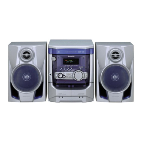
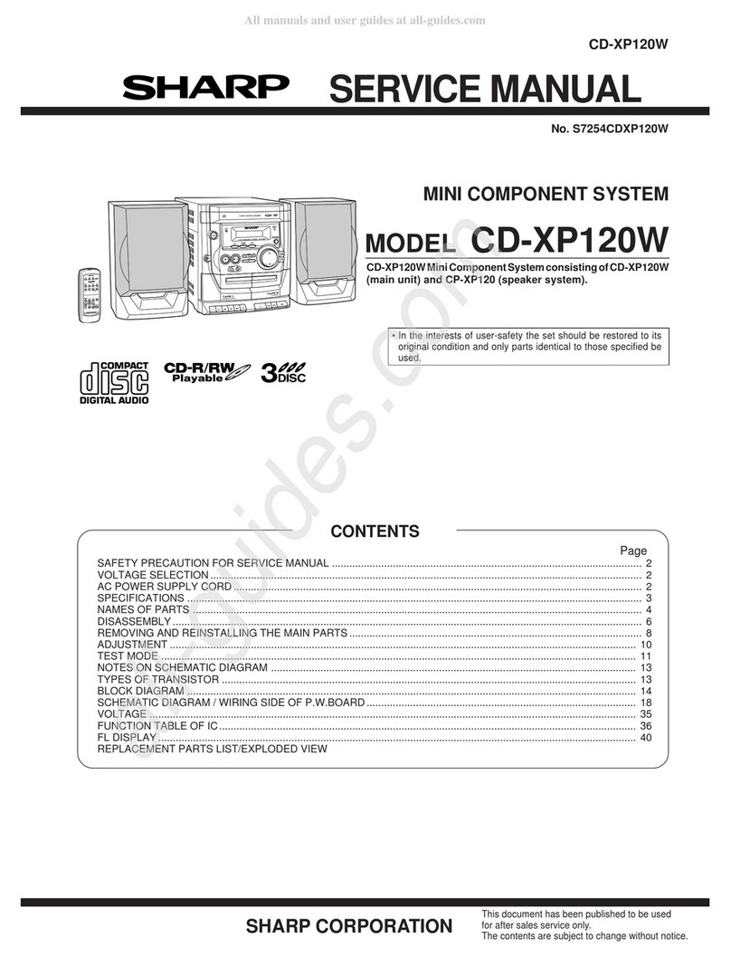
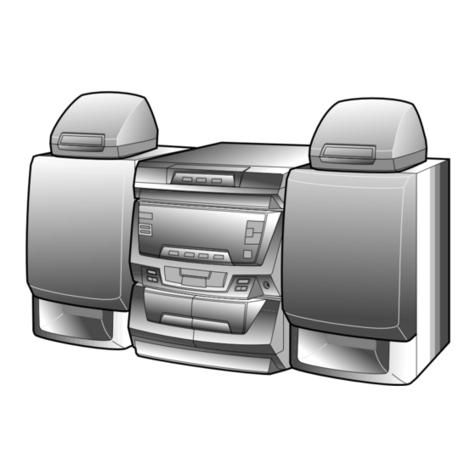
Sharp CD-C482 User manual

– 1 –
CD-C482
No.S7861CDC482//
CONTENTS Page
IMPORTANT SERVICE NOTES........................................................................................................................................ 2
SPECIFICATIONS ............................................................................................................................................................. 3
NAMES OF PARTS ........................................................................................................................................................... 4
OPERATION MANUAL ...................................................................................................................................................... 7
QUICK GUIDE ................................................................................................................................................................... 8
DISASSEMBLY................................................................................................................................................................ 11
NOTES ON SCHEMATIC DIAGRAM .............................................................................................................................. 14
BLOCK DIAGRAM ........................................................................................................................................................... 15
SCHEMATIC DIAGRAM / WIRING SIDE OF P.W.BOARD............................................................................................. 20
REPLACEMENT PARTS LIST/EXPLODED VIEW
PACKING OF THE SET
CD-C482
• In the interests of user-safety the set should be restored to its
original condition and only parts identical to those specified be
used.
SERVICE MANUAL
This document has been published to be used
for after sales service only.
The contents are subject to change without notice.
SHARP CORPORATION
Manufactured under license from Dolby Laboratories.
"Dolby", "Pro Logic" and the double-D symbol are trademarks
of Dolby Laboratories. Confidential Unpublished Works.
©1992-1997 Dolby Laboratories, Inc. All rights reserved.
This Serivce Manual is for the CD-C482, which is a
minormodification model of the CD-C492, This manual,
therefore, describes only the changed points from the
service manual. Pleasa refer to the CD-C492, service
manual (No. S5829CDC492//) together with this manual.
CD-C492
Page
REMOVING AND REINSTALLING THE MAIN PARTS............ 15
ADJUSTMENT .......................................................................... 16
WAVEFORMS OF MD CIRCUIT .............................................. 20
TROUBLESHOOTING .............................................................. 55
FUNCTION TABLE OF IC ........................................................ 59
FL DISPLAY.............................................................................. 70
QSOUND and the QLogo are registered trademarks of
QSound Labs, Inc.
QSound is protected under US Patent Nos. 5,105,462 and
5,208,860 and foreign counterparts.
CD-C482 mini component system consisting of
CD-C482 mini component system,
CP-C482 and CP-SW482 speaker system.

CD-C482
– 2 –
FOR A COMPLETE DESCRIPTION OF THE OPERATION OF THIS UNIT, PLEASE REFER
TO THE OPERATION MANUAL.
IMPORTANT SERVICE NOTES
BEFORE RETURNING THE AUDIO PRODUCT
(Fire & Shock Hazard)
Before returning the audio product to the user, perform the
following safety checks.
1. Inspect all lead dress to make certain that leads are not
pinchedorthathardwareisnotlodgedbetweenthechassis
and other metal parts in the audio product.
2. Inspect all protective devices such as insulating materials,
cabinet, terminal board, adjustment and compartment
covers or shields, mechanical insulators etc.
3. To be sure that no shock hazard exists, check for leakage
current in the following manner.
* Plug the AC line cord directly into a 120 volt AC outlet.
* Using two clip leads, connect a 1.5k ohm, 10 watt resistor
paralleled by a 0.15µF capacitor in series with all exposed
metal cabinet parts and a known earth ground, such as
conduit or electrical ground connected to earth ground.
* Use a VTVM or VOM with 1000 ohm per volt, or higher,
sensitivity to measure the AC voltage drop across the
resistor (See diagram).
* Connect the resistor connection to all exposed metal parts
havingareturnpathtothechassis(antenna,metalcabinet,
screw heads, knobs and control shafts, escutcheon, etc.)
and measure the AC voltage drop across the resistor.
AllcheckmustberepeatedwiththeAClinecordplugconnection
reversed.
Anyreadingof0.3voltRMS (thiscorrespondsto0.2milliamp.
AC.) or more is excessive and indicates a potential shock
hazard which must be corrected before returning the audio
product to the owner.
TO EXPOSED
METAL PARTS
CONNECT TO
KNOWN EARTH
GROUND
TEST PROBE
0.15 µ F
1.5k ohms
10W
VTVM
AC SCALE
ACCESSORIES
Remote control ×1
(RRMCG0141AWSA) FM antenna ×1
(92LFANT1746A) AM loop antenna ×1
(QANTL0006AWZZ)
Front speaker wire ×2
(92L3191SW49210)
(92L3191SW49210) Sub woofer wire ×1
(92L3191SW49210)

– 3 –
CD-C482
SPECIFICATIONS
●General
Power source: AC 120 V, 60 Hz
Power consumption: 120 W
Dimensions: Width; 10-5/8" (270 mm)
Height; 12-1/2" (316 mm)
Depth; 13-1/2" (343 mm)
Weight: 22.3 lbs. (10.1 kg)
●Amplifier section
Output power: Front speakers; 50 W minimum
RMS per channel into 8 ohms,
from 60 Hz to 20 kHz with no
more than 10 % total harmonic
distortion.
Sub woofer; 50 W
(80 Hz, 10 % T.H.D.)
Output terminals: Front speakers; 8 ohms
Sub woofer; 8 ohms
Monitor; 1 Vp-p/75 ohms
PRE OUT; 500 mV/47 kohms
Front Left Speaker
Front Right Speaker
Surround Left Speaker
Surround Right Speaker
Center Speaker
Sub Woofer
Headphones; 16 - 50 ohms
(recommended; 32 ohms)
Input terminals: DVD 1 (Digital); Optical
DVD 2 (Digital); Coaxial
VCR 1/AUX 1; 500 mV/47 kohms
VCR 2/AUX 2; 500 mV/47 kohms
DVD 1/VCR 1; 1 Vp-p/75 ohms
DVD 2/VCR 2; 1 Vp-p/75 ohms
●Tuner section
Frequency range: FM; 87.5 - 108 MHz
AM; 530 - 1,720 kHz
●Cassette deck section
Frequency response: 50 - 14,000 Hz (Normal tape)
Signal/noise ratio: 55 dB (TAPE 1, playback)
50 dB (TAPE 2, recording/
playback)
Wow and flutter: 0.15 % (WRMS)
●Compact disc player section
Type: 3-disc multi-play compact disc
player
Signal readout: Non-contact, 3-beam semi-con-
ductor laser pickup
D/A converter: 1-bit D/A converter
Frequency response: 20 - 20,000 Hz
Dynamic range: 100 dB (1 kHz)
●Front speaker section
Type: 3-way, 5-1/8" (130 mm) woofer,
2" (50 mm) tweeter and super
tweeter
Maximum input power: 100 W
Impedance: 8 ohms
Dimensions: Width; 8-11/16" (220 mm)
Height; 12-1/2" (316 mm)
Depth; 11-3/16" (284 mm)
Weight: 7.5 lbs. (3.4 kg)/each
●Sub woofer section
Type: 6-1/2" (160 mm) woofer
Maximum input power: 100 W
Impedance: 8 ohms
Dimensions: Width; 8-11/16" (220 mm)
Height; 12-1/2" (316 mm)
Depth; 11-5/8" (294 mm)
Weight: 8.4 lbs. (3.8 kg)
CP-C482
CD-C482
Specifications for this model are subject to change without prior notice.
CP-SW482

CD-C482
– 4 –
Front panel
1. Disc Tray
2. Disc Number Selector Buttons
3. Disc Skip Button
4. Open/Close Button:
5. Function Selector Buttons
6. Extra Bass Button
7. Volume Control
8. Power Button
9. Headphone Socket
10. Surround Mode Selector Buttons
11. Equalizer Selector/Demo Mode Button
12. Clock Button
13. Sleep Button
14. Reverse Mode Button: ( )
15. CD Pause Button:
16. Jog Dial
17. (CD/TAPE) Stop Button:
18. Record Pause Button:
19. Menu Button
20. Item Button
21. Timer Button
22. Memory Button
23. Clear Button
24. (CD) Track Down/Review Button:
(TAPE 2) Fast Wind Button:
(TUNER) Tuning Down Button:
25. (TAPE 2) Reverse Play Button:
26. (CD) Play/Repeat Button:
(TAPE 1) Play button:
(TAPE 2) Forward Play Button:
27. (CD) Track Up/Cue Button:
(TAPE) Fast Wind Button:
(TUNER) Tuning Up Button:
28. (TAPE) Normal Edit Button
29. (TAPE) High Edit Button
30. (TAPE 1) Cassette Compartment
31. (TAPE 2) Cassette Compartment
NAMES OF PARTS
CD-C482
1234
8
910 11
12 13 14 15 16 17 18 19 20
21 22 23 24 25 26 27 28 29
576
30 31

– 5 –
CD-C482
RATED SPEAKER IMPEDANCE : 8 OHMS MIN.
IMPEDANCE NOMINALE DU
HAUT-PARLEUR : 8 OHMS MINIMUM
1234
5
67 8
9
10
11
15 16 17
18
12
13 14
Rear panel
1. DVD 1 Digital Input Socket (Optical)
2. DVD 2 Digital Input Socket (Coaxial)
3. DVD 1/VCR 1 Video Input Socket
4. DVD 2/VCR 2 Video Input Socket
5. Video Output Socket
6. CD Digital Output Socket (Optical)
7. VCR 1/AUX 1 Input Socket
8. VCR 2/AUX 2 Input Socket
9. FM 75 ohms Aerial Terminal
10. Aerial Earth Terminal
11. AM Aerial Terminal
12. AC Power Lead
13. Front Speaker Terminals
14. Sub WooferTerminals
15. Front Speaker Output Socket
16. Surround Speaker Output Socket
17. Center Speaker Output Socket
18. Sub Woofer Output Socket
CP-C482
1
2
3
4
5
Front speakers
1. Super Tweeter
2. Tweeter
3. Woofer
4. Bass Reflex Duct
5. Speaker Terminals
CP-SW482
1
2
3
Sub woofer
1. Woofer
2. Bass Reflex Duct
3. Speaker Terminals

CD-C482
– 6 –
2
1
3
456
7
8
9
10
11
12
13
14
15 16
17 18 19 20
21
22
23
24
25 26
27
Remote control
1. Remote Control Transmiter LED
2. Surround Mode Selector Buttons
3. Sub Woofer Level Control Buttons: /
4. Setup Up/Down Buttons: /
5. Menu Button
6. Item Button
Tuner control section
7. Preset Up/Down Buttons: /
CD control section
8. Track Up/Cue Button: /
9. Track Down/Review Button: /
10. Memory Button
11. Disc Skip Button
12. Stop Button:
13. Play/Repeat Button:
14. Pause Button:
15. Clear Button
16. Random Button
Tape control section
17. (TAPE 2) Record Pause Button:
18. (TAPE 2) Reverse Play Button:
19. Stop Button:
20. (TAPE 1) Play Button:
(TAPE 2) Forward Play Button:
21. (TAPE 2) Fast Wind Buttons: /
Common section
22. Extra Bass Button
23. Equalizer Mode Button
24. Function Selector Buttons
25. Power Button
26. Volume Control Buttons
27. Dimmer Button

– 7 –
CD-C482
OPERATION MANUAL
SETTING THE CLOCK
1
Press the POWER button to enter the stand-by mode.
2
Press the CLOCK button.
3
Within 5 seconds, press the MEMORY button.
4
Turn the jog dial to select the time display mode.
"0:00" →The 24-hour display will appear.
(0:00 - 23:59)
"AM 12:00"→The 12-hour display will appear.
(AM or PM 12:00 - 11:59)
"AM 0:00" →The 12-hour display will appear.
(AM or PM 0:00 - 11:59)
●Note that this can only be set when the unit is first installed
or it has been reset (see page 36).
5
Press the MEMORY button.
6
Adjust the hour by turning the jog dial.
●When the jog dial is turned one click clockwise, the time will
increase by 1 hour. When it is turned one click counterclock-
wise, the time will decrease by 1 hour.
Keep turning the jog dial to change the time continuously.
●When the 12-hour display is selected, "AM" will change auto-
matically to "PM".
7
Press the MEMORY button.
8
Adjust the minutes by turning the jog dial.
●When the jog dial is turned one click clockwise, the time will
increase by 1 minute. When it is turned one click counterclock-
wise, the time will decrease by 1 minute.
Keep turning the jog dial to change the time continuously.
●The hour setting will not advance even if minutes advance from
"59" to "00".
9
Press the MEMORY button.
●The clock starts operating from "0" seconds.
(Seconds are not displayed.)
Note:
●In the event of a power failure or when the AC power cord is
disconnected, the clock display will go out.
When the AC power supply is restored, the clock display will
flash on and off to indicate the time when the power failure
occurred or when the AC power cord was disconnected.
If this happens, follow the procedure below to change the clock
time.
To change the clock time:
When the unit is in the stand-by mode:
➀Press the MEMORY button.
➁Perform steps 6 - 9 above.
When the unit is on:
➀Press the CLOCK button.
➁Within 5 seconds, press the MEMORY button.
➂Perform steps 6 - 9 above.
To see the time display:
Press the CLOCK button.
●The time display will appear for about 5 seconds.
To change the time display mode:
➀Perform steps 1 and 2 in the section "RESETTING THE MI-
CROCOMPUTER", on page 36.
➁Perform steps 1 - 9 above.
POWER
CLOCK
Jog dial
MEMORY TUNING
( )
In this example, the clock is set for the
12-hour (AM 12:00) system.
0:00 AM 12:00 AM 0:00
2
3
4
5
6
7
8
9
RESETTING THE MICROCOMPUTER
POWER
EQUALIZER
/DENO
Reset the microcomputer by performing the following
procedure for the cases shown below:
●To erase all of the stored memory contents, or
●If the display does not function properly, or
●The unit does not operate properly.
1
Press the POWER button to turn the power off.
2
Press the POWER button while holding down the
button and the EQUALIZER/DEMO button.
Caution:
●The operation explained above will erase all data stored
in memory including clock and timer settings, and tuner
and CD presets.
CD-C482
– 8 –
MINI COMPONENT SYSTEM
Quick Guide/Guía rápida
CD-C482
●Remote control x 1
●
Controlador remoto x 1
●2 “AA” batteries
●
Dos pilas “AA”
Remote sensor
Sensor remoto
3
Placing the speaker system /
Situación de los altavoces
2
How to use the remote control /
Empleo del controlador remoto
1
Check the supplied accessores /
Compruebe los accesorios suministrados
●FM antenna x 1
●
Antena de FM x 1
●AM loop antenna x 1
●
Antena de cuadro de AM x 1
●Front speaker wire x 2
●
Cable de altavoz frontal
x 2
●Sub woofer wire x 1
●
Cable de altavoz de
subgraves x 1
●Batteries are not included.
●
Las pilas no están incluidas.
+-
-
+
15
15
8” - 20’ (0.2m - 6m)
0,2m - 6m
4
Connecting the system /
Conexión del sistema
●How to switch between an audio signal and a
video signal
●
Cómo cambiar entre una señal de audio y una
señal de vídeo
BUTTON/
BOTÓN
“DVD 1”
AUDIO OUTPUT/
SALIDA DE AUDIO
VIDEO OUTPUT/
SALIDA DE V?DEO
DISPLAY/
VISUALIZACIÓN
“VCR 1”
“DVD 2”
“VCR 2”
DVD 1
VCR 1/AUX 1
DVD 2
VCR 2/AUX 2
DVD 1/VCR 1
DVD 1/VCR 1
DVD 2/VCR 2
DVD 2/VCR 2
TV
TV
Video
Video
Audio(Optical)
Audio(Coaxial)
Audio
R
R
L
L
Video
Audio(Analog)
DVD
DVD
VCR
VCR 120 V de CA, 60 Hz
AC 120 V, 60 Hz

– 9 –
CD-C482
123
AM Loop Antenna
Antena de cuadro de AM
FM Antenna
Antena de FM
SUB WOOFER
ALTAVOZ DE
SUBGRAVES
RIGHT
DERECHO
LEFT
IZQUIERDO
Red
Rojo
Black
Negro
Red
Rojo
Black
Negro
FRONT SPEAKER
ALTAVOZ FRONTAL
Red
Rojo
Red
Rojo
Black
Negro
Black
Negro
Red
Rojo
Black
Negro
Front speaker
Altavoz delantero
Front speaker
Altavoz delantero
Surround speaker
Altavoz de sonido
perimétrico
Surround speaker
Altavoz de sonido
perimétrico
Center speaker
Altavoz central
Amplifier
Amplificador
Amplifier
Amplificador
Amplifier
Amplificador
Amplifier
Amplificador
Sub woofer
Subgraves
EXPANDED SPEAKER SYSTEM
SISTEMA DE ALTAVOCES AMPLIADO
5
Listening to a CD /
Audición de discos CD
Press the POWER button to
turn the power on.
Pulse el botón POWER para
conectar la alimentación.
1
Press the CD button.
Pulse el botón CD.
Press the OPEN/CLOSE button to
open the disc tray and place the CD (s)
on the disc tray, label side up.
Pulse el botón OPEN/CLOSE para abrir la
bandeja del disco y coloque el disco(s) CD en la
bandeja del disco con el lado de la etiqueta arriba.
2
3
Press the OPEN/CLOSE button
to close the disc tray.
Pulse el botón OPEN/CLOSE
para cerrar la bandeja del disco.
4
Press the button.
Pulse el botón .
5
Adjust the volume level.
Turn the VOLUME control clockwise
to increase the volume.
Turn the VOLUME control
counterclockwise to decrease the
volume.
Ajuste el nivel de volumen.
Girando el control VOLUME hacia
la derecha se incrementa el
volumen.
Girando el control VOLUME hacia
la izquierda se reduce el volumen.
6
To stop the playback
Para detener la reproducción
Press the button.
Pulse el botón .
VOLUME

CD-C482
– 10 –
6
Listening to a tape /
Audición de una cinta
7
Listening to the radio /
Audición de la radio
Load a cassette into the cassette
compartment.
Inserte un casete en el
compartimiento del casete.
3
Press the POWER button to
turn the power on.
Pulse el botón POWER para
conectar la alimentación.
1
Press the TAPE button to select
"TAPE 1" or "TAPE 2".
Pulse el botón TAPE para
seleccionar "TAPE 1" o "TAPE 2".
2
TAPE 2
TAPE 1
Press the button.
Pulse el botón .
4
To stop the playback
Para detener la reproducción
Press the button.
Pulse el botón .
Press the TUNING ( / ) button
to tune in to the desired station.
Pulse el botón TUNING ( / )
para sintonizar la emisora
deseada.
3
Press the POWER button to
turn the power on.
Pulse el botón POWER para
conectar la alimentación.
1
Press the TUNER (BAND) button
to select "FM ST" ,"FM"or "AM".
Pulse el botón TUNER (BAND) para
seleccionar "FM ST", "FM", o "AM".
2
8
Recording from CDs /
Grabaciones de discos CD
Press the POWER button to
turn the power on.
Pulse el botón POWER para
conectar la alimentación.
1
Press the TAPE (1 2) button to
select the "TAPE 2".
Pulse el botón TAPE (1 2) para
seleccionar "TAPE 2".
2
3
Press the REVERSE MODE button
to select the reverse mode.
Pulse el botón REVERSE MODE
para seleccionar el modo de
inversión.
4
Press the CD button and load the
desired disc.
Pulse el botón CD y coloque el
disco deseado.
5
Press the NORMAL EDIT button.
Pulse el botón NORMAL EDIT.
6
•••••
One side /
Una cara
•••••
Both side /
Ambas caras
TAPE 2
Load a cassette into the
TAPE2 cassette compartment.
Inserte un casete en el
compartimiento del
casete de TAPE 2.
To stop the recording
Para detener la grabación
Press the button.
Pulse el botón .

– 11 –
CD-C482
1 Top Cabinet 1. Screw ..................... (A1) x4 11-1
2 Side Panel 1. Screw ..................... (B1) x8 11-1
(Left/right)
3 CD Player Unit/ 1. Turn on the power supply, 11-2
CD Tray Cover open the disc tray, take out 12-1
the CD cover, and close.
(Note 1)
2. Hook....................... (C1) x3
3. Hook....................... (C2) x2
4. Screw ..................... (C3) x1
5. Socket .................... (C4) x3
4 Dolby PWB 1. Flat cable ............... (D1) x2 12-1
2. Socke ..................... (D2) x1
3. Screw ..................... (D3) x11
5 Tuner PWB 1. Socket .................... (E1) x1 12-1
2. Screw ..................... (E2) x5
6 Rear Panel 1. Screw ..................... (F1) x10 11-2
7 Main PWB 1. Flat cable ............... (G1) x2 12-2
2. Flat wire .................
(G2) x1
3. Socket...................... (G3) x4
4. Screw....................... (G4) x3
8 Front Panel 1. Flat wire ................. (H1) x1 12-2
2. Screw...................... (H2) x2
10
Power Amp. PWB
1. Socket .................... (K1) x2 12-3
2. Screw ..................... (K2) x6
11
Power Supply PWB
1. Screw ..................... (L1) x6 12-4
12 Display PWB 1. Knob....................... (M1) x2 12-4
2. Nut.......................... (M2) x2
3. Screw ..................... (M3)x12
13 CD Switch PWB 1. Screw ..................... (N1) x3 12-4
14 Headphones 1. Screw ..................... (P1) x1 12-4
15 Tape Mechanism 1. Screw ..................... (Q1) x6 12-4
16 Turntable 1. Screw ..................... (R1) x1 12-5
2. Cover ..................... (R2) x1
17 Disc Tlay 1. Screw ..................... (S1) x2 12-5
2. Guide ..................... (S2) x2
18 CD Player Unit/ 1. Screw ..................... (T1) x1 12-5
CD Servo PWB 2. Socket .................... (T2) x4
19 CD Changer 1. Screw ..................... (U1) x4 13-1
Mechanism
20 CD Mechanism 1. Screw ..................... (V1) x1 13-1
DISASSEMBLY
Caution on Disassembly
Follow the below-mentioned notes when disassembling
the unit and reassembling it, to keep it safe and ensure
excellent performance:
1. Take cassette tape and compact disc out of the unit.
2. Be sure to remove the power supply plug from the wall
outlet before starting to disassemble the unit.
3.Takeoff nylon bands or wire holders where theyneedto
beremovedwhendisassemblingtheunit.Afterservicing
theunit,be sure to rearrange the leads where theywere
before disassembling.
4. Take suffcient care on static electricity of integrated
circuits and other circuits when servicing.
Figure 11-2
Figure 11-3
CD-C482
STEP REMOVAL PROCEDURE FIGURE
Note 1:
How to open the changer manually. (Fig. 11-3)
1. Then, turn fully the lock lever in the arrow direction through
the hole on the loading chassis bottom in this state.
After that, push forward the CD player base.
Figure 11-1
CD-C482
( B1 ) x2
ø3 x8mm
( B1 ) x4
ø3 x8mm ( B1 ) x2
ø3 x8mm
Top Cabinet
Side Panel
(Right)
Rear Panel
Side Panel
(Left)
( A1 ) x2
ø3 x12mm
( A1 ) x2
ø3 x12mm
CD Tray Cover
CD Player
Unit
( F1 ) x10
ø3 x8mm
( C3 ) x1
ø3 x8mm
Hook
( C1) x3
( C2 ) x1
( C4 ) x2
Rear Panel
Main PWB
Front Panel
1
1
2
Tuner PWB
Pull
(C2) x1
LOCK
LEVER

CD-C482
– 12 –
Figure 12-1
Figure 12-2
Figure 12-3
Figure 12-4
Figure 12-5
Figure 12-6
(E2) x4
ø3 x10mm
(D3) x4
ø3x10mm
(F1) x1
ø3 x10mm
(D3) x8
ø3x10mm
(E2) x1
ø3x10mm
(G4) x2
ø3x10mm
(G4) x1
ø3x10mm
(G3) x2
(G1) x1
(D1) x1 (G2) x1
(G3) x2
(G ) x2
Rear Panel
Main PWB
Tuner PWB
Dolby PWB
Front Panel
(D2) x1
(C4) x1
(D1) x1
(E1) x1
(J2)x4
ø3x10mm
(K2)x5
ø3x10mm
Front Panel
( K2 ) x1
ø3x10mm ( H2 ) x1
ø3x10mm
( K1 ) x2
( H1 ) x1
Heat Shink Cover Power Amp. PWB
(L1)x4
ø4x8mm
(L1)x1
ø3x10mm
(L1)x1
ø3x10mm
Power Supply PWB
(N1)x3
ø3x10mm
(M3)x12
ø3x10mm
(Q1)x6
ø3x10mm Lug Wire
(P1)x1
ø3x10mm
Open
Headphones
PWB
Display
PWB
(M1)x2
(M2)x1
(M2)x1
Washer
Tape Mechanism
Cassette
Holder (Left/Right)
Front Panel
CD Switch PWB
( S1 ) x1
ø3 x10mm
( S1 ) x1
ø3 x10mm
( R1 ) x1
ø3 x10mm
Turntable
Disc Tray
( R2 ) x1
( S2 ) x1
( S2 ) x1
CD Player Unit
( T1 ) x1
ø3 x10mm
( T2 ) x2
( T2 ) x2 CD Player Unit
CD Servo PWB

– 13 –
CD-C482
CP-C482
1 Front Speaker 1. Net.......................... (A1) x1 13-2
2. Baffle Board ........... (A2) x1
3. Screw ..................... (A3) x2
4. Screw ..................... (A4) x4
5. Screw ..................... (A5) x2
STEP REMOVAL PROCEDURE FIGURE
CP-C482
Figure 13-2
CP-SW482
Figure 13-3
CP-SW482
1 Sub woofer 1. Net.......................... (A1) x1 13-3
2. Duct Panel ............. (A2) x1
3. Screw ..................... (A3) x4
STEP REMOVAL PROCEDURE FIGURE
Note:
The center and rear speakers can be easily disassembled.
Therefore the disassembling method is not discribed.
For details refer to the disassembling drawing in the Parts
Guide.
Be careful when installing the CD changer mechanism.
InstalltheCDchangermechanismontheCDplayerbaseafter
the shift lever has been set in the highest position.
Figure 13-1
Screw driver
Woofer
Woofer
Net
(A1)x1
Baffle Board
(A2)x1
Tweeter
Tweeter
Super
Tweeter (A5)x2
ø3x10mm
(A3)x2
ø3x10mm
(A4)x4
ø4x16mm
( A3 ) x4
ø4 x16mm
Net
( A1 ) x1
( A2 ) x1 Screwdriver
Woofer
( U1 ) x4
ø3 x12mm
( V1 ) x1
ø2.6 x10mm
CD Changer
Mechanism
CD Mechanism
Shift Lever
CD Player Base

CD-C482
– 14 –
SW1 OPEN/CLOSE ON—OFF
SW2 MECHA UP ON—OFF
SW3 DISC NUMBER ON—OFF
SW4 PICKUP IN ON—OFF
SWD1 VOLUME ON—OFF
SWD2 JOG ON—OFF
SWD3 X-BASS ON—OFF
SWD4 PRE EQ ON—OFF
SWD5 MENU ON—OFF
SWD6 ITEM ON—OFF
SWD12 TUNING UP/CUE ON—OFF
SWD13 STOP ON—OFF
SWD14 NORMAL EDIT ON—OFF
SWD15 REC. PAUSE ON—OFF
SWD16 REC/PAUSE ON—OFF
SWD17 F-PLAY ON—OFF
SWD23 QSOUND ON—OFF
SWD26 VIRTUAL ON—OFF
SWD27 PHANTOM ON—OFF
SWD28 NORMAL ON—OFF
SWD29 BYPASS ON—OFF
SWD30 TUNING DOWN/REWIND ON—OFF
SWD31 CD PAUSE ON—OFF
SWD32 REVERSE MODE ON—OFF
SWD33 R-PLAY ON—OFF
SWD34 CLOCK ON—OFF
SWD35 MEMORY ON—OFF
SWD36 TIMER ON—OFF
SWD37 SLEEP ON—OFF
SWD38 CLEAR ON—OFF
SWD39 DVD/VIDEO 1 ON—OFF
SWD40 DVD/VIDEO 2 ON—OFF
SWD41 TAPE 1/2 ON—OFF
SWD42 TUNER/BAND ON—OFF
SWD43 CD ON—OFF
SWD48 POWER ON—OFF
SWD50 DISC 1 ON—OFF
SWD51 DISC 2 ON—OFF
SWD52 DISC 3 ON—OFF
SWD53 DISC SKIP ON—OFF
SWD54 OPEN/CLOS ON—OFF
SWM3 REC FWD ON—OFF
SWM4 REC RVS ON—OFF
SWM5 F.A.S ON—OFF
SWM6 CAM ON—OFF
•The indicated voltage in each section is the one measured
by Digital Multimeter between such a section and the chas-
sis with no signal given.
1. In the tuner section,
( ) indicates AM
< > indicates FM stereo
2. In the main section, a tape is being played back.
3. In the deck section, a tape is being played back.
( ) indicates the record state.
4. In the power section, a tape is being played back.
5. In the CD section, the CD is stopped.
•Parts marked with “ ” ( ) are important for
maintaining the safety of the set. Be sure to replace these
parts with specified ones for maintaining the safety and
performance of the set.
NOTES ON SCHEMATIC DIAGRAM
•Resistor:
To differentiate the units of resistors, such symbol as K and
M are used: the symbol K means 1000 ohm and the symbol
M means 1000 kohm and the resistor without any symbol is
ohm-type resistor. Besides, the one with “Fusible” is a fuse
type.
•Capacitor:
To indicate the unit of capacitor, a symbol P is used: this
symbol P means micro-micro-farad and the unit of the
capacitor without such a symbol is microfarad. As to
electrolyticcapacitor,theexpression“capacitance/withstand
voltage” is used.
(CH), (TH), (RH), (UJ): Temperature compensation
(ML): Mylar type
(P.P.): Polypropylene type
•Schematic diagram and Wiring Side of P.W.Board for this
model are subject to change for improvement without prior
notice.
REF. NO DESCRIPTION POSITION POSITIONREF. NO DESCRIPTION
Figure 14 TYPES OF TRANSISTOR
KTA1266 GR
KTA1270Y
KTA1271 Y
KTA1273 Y
KTC3199 GR
KTC3203 Y
KRA102 M
KRA107 M
KRA109 M
KRC102 M
KRC104 M
KRC107 M
2SC535 C
2SD468 C
2SC2878 A
2SD2012
2SB1375
SLR325 MG
SLR325 VR
KL052 UL
SLR505 MC
LMKD515 B
KV1236Z23
(S)(G)(D)
(1) (2) (3)
E C B
FRONT
VIEW
FRONT
VIEW
B C E
(D)(G)(S)
(3) (2) (1)
FRONT
VIEW
FRONT VIEW

– 15 –
CD-C482
Figure 15 BLOCK DIAGRAM (1/5)
8
27
1
2
3
4
5
98
6
7
20
12
13
24
25
30
31
3222
34
35
36
10 11
27
26
28
29
PU-IN SW
XL1
XIN
LD0
FIN2 JP–
CV+
SLC
SL1
FIN1
E
F
TO
FD
SPO
NC
SLD
SL–
SL+
DRF
CL
DAT
CE
VCC1
6
+5V
PICKUP IN
SW4
FOCUS COIL
TRACKING COIL
M1
DISC
MOTOR
M
M
M2
SLIDE
MOTOR
PICKUP UNIT
9
IC2
LC78622K
SERVO/SIGNAL
CONTROL
+B1
IC3
M56748FP
DRIVER
IC1
LA9241M
SERVO AMP.
6
1
95
+B1
+12V(+B5)
RES. CQCK. COIN
SQOUT. RWC. WRQ
~
~
~
CL, DAT, SELIAL CONTROL/CE Q93
Q91
Q91
SL+. SL–. DRF
7
3
9
8
7
6
5
4
3
2
1
GND (D)
MECHA UP
GND (D)
DISK NO.
OPEN/CLOSE
GND (D)
M–
M+
GND (M)
9
8
7
6
5
4
3
2
1
CNP10
M
+5V
+B1
62 64 45 3623 43
31
24
25
10 10
265853
10
12
20
32
40
43
44
5352515431302923271615
4144
Q1 Q52
+4.3V Q81 +7.3V (B1)
REGULATOR
TO MAIN SECTION
IC81
TA7291S
LORDING MOTOR
DRIVER
XOUT
EFMO
EFMIN
CLV+
JP–
CONT2
CONT1
CONT4
DOUT
VVDD
VDD
LVDD
RVDD
XVDD
SW1
OPEN/CLOSE
SW2
MECHA UP
SW3
DISC No.
M3
LOADING
SOLM1
TO MAIN
SECTION
CNS10

CD-C482
– 16 –
Figure 16 BLOCK DIAGRAM (2/5)
13
8
10
1 4
6
7
14
TOS
ICA14
GP1F38R
DVD2
DIGITAL
IN
ICA15
TC74HCU04
INVERTER
IN
IN
DVD2
DIGITAL
IN
FROM CD UNIT
4
3
5
6
7
1 6
11 ~ 1315
+B13
IN
IN
IN
ICA16
TC74HCU15
SWITCH
61
D4-GND D4-GND
14
13
12
11
D-OUT
DEM0
DEM1
16
17
15
SCK
CLK
CLK2L/R
83 79 91
D-IN
CLK2L/R OUT
92
CLK2OUT
97 95 66
CLK2
CLK
SCK
SCK2IN
90
78
94
86
85
62
60
36
4
2 8
D3-GND
D-OUT D-IN
SL/SR OUT
SL/SR IN
D
O
M
ANAROG LCH
4 7
IN
2 1 6
7
IN
6
3
4
5
6
23 24
PWDA
PWAD
AINR+
AINR–
AINL+
AINL–
2
8
18
19
20
22
25
1 7 9
10 21
+B13+B9
AINR–
AINL–
AINL+
IN
IN
OUT
OUT
OUT
ICA13
AK4520A
A/D,D/A
CONVERTER
ANAROG RCH
ICA11
NJM4580M
LOW PASS FILTER &
DIFFERENTIAL AMP
A-GND
8
4
2 1
8
+B7
A-GND
A-GND
+B7
ICA12
NJM4580M
LOW PASS FILTER &
DIFFERENTIAL AMP
27
LS OUT
RS OUT
26
VIDEO1 IN
VIDEO2 IN
MONITOR
OUT
1
7
3
+B7
2
4
8
5
+B7
ICH51
NJM2246M
SWITCH
QH51
V-GND
LS/RS
OUT
DGTL2
V1/V2
16
+B13
2 DGTL2
9
14
DGTL1
V1/V2
DGTL2
DGTL1
QH52
QH53 DGTL2
V1/V2
SWITCHING
SWITCHING

– 17 –
CD-C482
Figure 17 BLOCK DIAGRAM (3/5)
7
9
12
13
5
DEM0
DEM1
XT1
BICK
LRCK
6
PD
16
20
22
2
14
15
24
8
18
17
+B9
1 3
10 11 21
A-GND
D3-GND
CENTER
SUB
WOOFER
CENTER
SUB
WOOFER
54
80
7
9
12
13
5
DEM0
DEM1
XT1
BICK
LRCK
6
PD
16
20
22
2
14
15
24
8
FL/FR
18
17
FL
FR
+B9
1 3
10 11 21
A-GND
D3-GND
89
87
82
34
3
SS
SO
RESET
SCK
SI
6
CLK2L/R
CLK
SCK
5
55 59 67 70 81 84 93
+B13
6
12 17 30 35 45
48
90
78
4
2 8
19 29 37 44 53 65 68 71
D3-GND
CENTER
SUB
WOOFER
OUT IN
IN OUT
FL/FR OUT
ICA18
ZR38600
DOLBY AC-3 /5.1
MPEG2 AUDIO
DECORDER
SUB
WOOFER
OUT FL/FR
OUT CENTER
OUT
SS
SO
SCK
SI
DEMO1
DEMO0
AC3 RESET
SUB
WOOFER
ON/OFF
AD RESET
4
8 SUB
WOOFER
IN
4
5 6
12
13
QA03
11
10
A-GND 7
14
QA01
QA02
–B12
+B12
8
1
9
2 5
7
–B12
+B7
ICA21
NJM4580M
–15dB AMP
SUB
WOOFER
OUT
SUB
WOOFER
ON/OFF
SWITCHING
FL/FR
VOLTAGE
REGURATER
VOLTAGE
REGURATER
+B7
+B12
–B6–B12
VOLTAGE
REGURATER
UN-SWITCHED
+B9
+B13 QB01
ICA19
AK4321
D/A
CONVERTER
ICA20
AK4321
D/A
CONVERTER
GND
VDD
4
8
+B7
–B12
3
5
1
7 IN
MIX
L
R
OUT
ICB01
NJM4580M
MIX AMP
SUB
WOOFER
ICA22
BU4066BCE
SWITCH

CD-C482
– 18 –
Figure 18 BLOCK DIAGRAM (4/5)
7
1
24
2
23
3
4
4
21
5
20
6 7
17
18
8
9
16
12 10
15 19
13
14
1
2 3 4 5 7 8
6
9
1 5
3 6 21
16
24 22
23
13
20
16
15 11
7
17
15
10
11
20 1 22
21
6
3
4
5
17
7
9
10
20
19
18
1
7
40
41
42
4
4
27
21
10 9
5
3
7
1
8
4
7 16
12
1
14
5
15
11
2
4
2
8
4
1
7 3
5
8
4
1
7 3
5
8
4
1
7 3
5
FM
AM
SPE IN
H/N
T1/T2
ERASE
HEAD
R–CH
L–CH
PB HEAD
L–CH
R–CH
REC/PB
HEAD
P.B
AC BIAS
P.B
REC
TAPE 2
TAPE 1
T1/T2
SWITCHING SWITCHING
BAIS
L NF
L(T1)
R(T1)
L(T2)
R(T2)
R NF
L
R
POP REDUCE
L REC
R REC
ICK01
AN7345K
PLAYBACKuRECORD AMP
L
R REC
P.B.
REC
ALC
NOR/
HIGH T1/T2
REF
+B7
P.B
REC/PB
MUTING
MUTING
PB MUTE
REC MUTE
HI SPEED
L NF
R NF
SWITCHING
SWITCHING
SWITCHING
M
MOTOR
+B2
TA MOT H/L
HI SPEED
TA MOT SW
DRIVER
MOTOR
DRIVER
T2 A/B-FP
SWM3
SWM4
T1 RUN SW
CAM SW
FAS SW
PHM1
TA PUL
+B2
SOLM1 DRIVER
TA CUM SW
BAIS
T2 PH–IN
T2 PH-OUT
FM BPF FM IF
OSC BUFF
FM RF
FM
OSC
Q302
T302
A1064
AM RF
AM ANT
IC301
FM FRONT END
TA7358AP
BF301
L302
T301
T304
B1074
AM OSC
FM IF
CF301
FM OSC
FM +B
Q344
+B7
GND
AM IF
FM IF IN
AM MIX
IC303
LA1805
FM/AM IF+MPX
FM DET
FM DET
MO/ST
T351
FM IN
AM IN
IC302
LC72131
PLL CONTROLLER
+B7 +B7
AM OSC IN
AM+B
AM RF IN
STEREO
+B7
+5V
MONO/ST
FM MONO/ST
VOLTAGE
REGURATER
OSC
X352
4.5MHz
FM/AM DET OUT
MPX IN
FM +B
Q342
Q343
L
DI
CL
CE
DO
FMOSC
FM
FM/AM
SWITCHING
IC
Q
QS7
7
QS
O
L
B.P.F
T352
VR351
MPX VCO ADJ
R
L–IN
R–IN L–OUT
R–OUT
C–IN C–OUT
SL
–
IN SL
–
OUT
TO AC-3
L
R
L
R
R
L
L
R
TAPE L
R
R L
R L
IN
OUT
ICZ09
NJM4565D
LINE AMP.
–B10 +B10
+B10
–B10
TUNER
VCR 1
VCR 2
ICH11
NJM4558M
MOTOR DRIVER
ICZ08
TC4052BP
DUAL 4CH ANALOG
MULTIPLEXER
QK21
QK22
QK26
QK24
QK28
LK04
QK07
QK08
QK11QK10
QK09
QK03 QK05
QK04 QK06
QK19
QK15
QK16
QL15
DRIVER
QL13
QL11
QL12
QL19
QL18
QL14
QK17
QK18
L
JR12
VCR/AUX2
+B7
–B6
OUT
+B7
–B6
OUT
L
R
IN
+B7
–B6
OUT
ICR13
NJM4565M
BUFFER AMP.
ICR12
NJM4565M
BUFFER AMP.
R
L
L
R
L
R
LS
RS
RS
C
C
SW SW C
JR13
PRE-OUT
FUNC–B
FUNC–A
MUTE
MUTE
MUTE
L
JR11
VCR/AUX1
QR19
QR20
QR17
QR18
QR15
QR16
LS
SO301
ANTENNA
TERMINAL
L303
R
AM IF VCC VCO
IN
SW
ICR14
NJM4565M
BUFFER AMP.
IN
QL17
R
R
REC/PB

– 19 –
CD-C482
Figure 19 BLOCK DIAGRAM (5/5)
8
4 1
7
3
5
23
19
15 89 18 26
45 47 50 52 71 73
29
15
89
57
18
56
90
12
16
17
27
13
14
11
4
3
5
1 467290 51 2728
1314
1
2
62
7
10
12
5
3 1
18
9
8
20
57
5 53
75
30
21
4
8 10
79 94
91 88
95
96
97
1
9
18
17
16
4
1
42
44
45 31
15
13
12
11
10
17
16
11
9
8
6 36
31
32
33
34
35
1
2
100
1
12
626160
30
31
32
33
34
35
29
37
38
39
40
41
42
43
44
45
46
47
48
49
36
7574 73 54
2426274950 5152 6364656682 76
6867 7170
9
8
7
10
9
8
7
6
78798788 9192 939495 969798 99
84
85
86
69
39
40 41
585653
16
17
30
5
1
15
14
42
R
L
IN OUT
L
R
ICF01
IX0233AW
SYSTEM MICROCOMPUTER
~
SPE1~5 ~
~
~ VSS
~
RES +B6
CQCK
COIN
SQ OUT
WRQ
RWC
CD SL+
CD-PUIN
CD-DRF
+B4 (5V BACK UP)
+B3
VDD +5V
UNSWITCH
+B2
MEMORY
BACK UP
VSS +B4
RESET
OSC
X201
4.19MHz
SYSTEM STOP
P.FAIL DET
+B3
RESET IN
CD SL-
+B2
VDD
–VP JOG SW
~
~
+B7
QP03
QP04
POWER ON/STB
POWER
SWITCHING
+ L–CH
M
FAN
FAN
MOTOR
+B6
PROT
RELAY
H/P SW
SP DET
L–IN
R–IN
POSISTOR
(AC)
(AC)
KEY MATRIX
KEY IN
TO CD UNIT
–B +B
Q907
ICP11
NJM4565D
LOW BOOST AMP.
ICV01
STK407-250
POWER AMP.
R–OUT
L–CH
–GND
+R–CH
–GND
+
–GND
QV20
QV21
QV22
QY12
QV13
QV14
QY11
VOLTAGE
REGULATOR
SWITCHING
VOLTAGE
REGULATOR
+12V(ANALOG)
+12V(MOTOR)
UN-SWITCHED
+B2
+B6
+B7
–15V
–B6
VOLTAGE
REGULATOR
+7.3V(CD)
TO CD UNIT
T.F
VF1 VP VF2
(AC) (AC)
VOLTAGE
REGULATOR
+B
–B
D991
F995
10A 125V
F996
10A 125V
T991
POWER
TRANSFORMER
Q951
F998
1.6A 250V
F997
2.5A 250V
D992~D995
F990
5A
125V
VOLTAGE
REGULATOR
D996~D999
Q911
Q910
+5V(AC-3)
Q904
Q903
Q902
Q901
Q906
Q905
+B8
+B9
Q909
Q908
+4.6V
SL–IN
C–IN
JV91
HEADPHONES
TMV01
SPEAKER
TERMINAL
FD01
FL DIPLAY
F1
F1
F2
F2
VF1
VF2
ICD01
IX0334AW
FL DRIVER
CONTROLLER
RXD01
REMOTE
SENSOR
SWD01
~
LEDD01~
LEDD28
DAT
COM SWD03~SWD06
SWD12~SWD17
SWD23~SWD48
SWD50~SWD54
ICQ01
QS7777PF
QSOUND
R
R–IN R–OUT
C–IN C–OUT
SL–IN
SR–IN SL–OUT
SR–OUT
MO
AC
AR
BYP
+B7
+B7
VOLTAGE
REGURATER
L–IN
R–IN L–OUT
R–OUT
C–IN C–OUT
ICZ10
M62446FP
6–ch VOL
SR–IN
SL–IN SR–OUT
SL–OUT
SW–OUT
SW–IN
QV18
–B6
STB
RES
TUNER MUTE
TU-DO
TU-SD
T1 CrO2
T1 RUN
T2 RUN
T2 A FP
T2 B FP
T2 CrO2
CAM-SW
TAPE SOL
TA MOT
FR SP
BIAS
TA R/P
PB EQ
REC EQ
REC MUTE
REC MUT
T1/T2
PB MUTE
QS2AR
QS2AC
FAN
SP DET
POSISTOR
H/P SW
PROT
FRONT RELAY
SURROUND RELAY
CENTER RELAY
S-W RELAY
S-MUTE
POWER
S-W-MUTE
CENTER-MUTE
SURROUND-MUTE
QG01
QG02
QG03
ZDF01
FUNC B
FUNC A
STB
SCK
DAT
STB
RES
SCK
DAT
COM
AD RES
SW ON/OFF
DIGITAL1
DIGITAL2
AC32SI
AC32SCK
V1/V2
DEM 0
DEM 1
AC-3 SECTION
CD U/D
CD O/C
CD DNO
VR CLK
VR ST
VR DATA
VR CLK
VR ST
VR DATA
DI
TU CL
CLK2
ICZ01
LC7522
G.E. VOL
ICZ03,05,07
NJM4565D
IN/OUT
FILTER
AMP
ICZ04,06,08
NJM4565D
IN/OUT
FILTER
AMP
DI
CLK
VOLTAGE
REGULATOR
QZ01
+B10
–B10 QZ02 VOLTAGE
REGULATOR
VOLTAGE
REGULATOR
VOLTAGE
REGULATOR
–B10
+B10
RLYV11
RLYY11
RELAY
+B10
+B10
-B10
–B10
VOLTAGE
REGURATER
+B7
+B11
+B11
–B10
+B10
+B11
S-MUTE
SW-MUTE
SW–OUT
SW–CH
QP15
AC32SS
AC32RES
AC32SO
SCK
~~~
VEE
SWD02
HIGH SP
QS2MO
QV19

CD-C482
– 20 –
Figure 20 SCHEMATIC DIAGRAM (1/20)
A
B
C
D
E
F
G
H
123456
• NOTES ON SCHEMATIC DIAGRAM can be found on page 14.
R46
560
FSS
LDO
DEF
CLK
CL
DAT
CE
DRF
VCC2
REF1
VR
LF2
PHI
BHI
LDS
10
1
8
9
12
C85
0.001
R47
10K
C25
27P R39
1K
C15
0.01
R41
47K
R43
56K
R44
33K
R42
47K
R28 10K
R29 56K
C17
0.001
R30
6.8K
R20
1K
R19
1K
C3
1/50
R34
22K
R48
10K
C36
100/16
IC3
M56748FP
FOCUS/TRACKING/SPIN
/SLIDE DRIVER
R11
6.8K
C6
0.033
R10
2.2K C5
0.033
C54
0.001
R8
15K
R9
100K
C16
0.0047
R27
39K
R25
1.5K
R23
10K
R24
47K
R17
33K
C29
4.7/50
C28
0.1
C14
0.01
C4
0.1
C35
1/50
R1
10
Q1
KTA1266 GR
R18
15K
C11
0.1
D3
RL104A
R35
220K C21
0.0033
R36
220K
C20
47/16
C19
1/50
R33
1.2K
R32
10K
C32
0.01
C31
220/6.3
C30
0.1/50
C27
0.001
C24
2.2P
R40
5.6K
C26
0.033
R31
1.2K
C18
0.47/50
R16
3.3K
R15
12K
C10
180P
C8
0.068
C7
0.1/50
R12
100
D4
RL104A
D2
RL104A
C9
0.047
R13
1K
R14
27K
C12
0.1
R2
1K C1
47/16
C2
0.01
CNP3
R38
470 C23
0.0027
R45
4.7K
C22
220
P
IC1
LA9241M
SERVO AMP.
16
15
14
13
12
11
10
9
8
7
6
5
4
3
2
1
C13
330P
R37
82K D1
1SS133
R22
22K
R21
22K
C34
0.33/50
C33
0.47/50
1
2
3
4
5
1
2
3
4
5CNP1
1
2
3
4
5CNS1A
CNS1B
32
33
34
35
36
37
38
39
40
41
42
43
44
45
46
47
48
31
30
29
28
27
26
25
2423
22
21
20
19
18
17
1234
5
CNP12
15
16
17
18 19
20
21
22
23
24
25
26
27
28
29
30
31
32
33
34
35
36
1
2
3
4
5
6
7
8
9
10
11
12
13
14
1
2
3
4
5
6
1
2
3
4
5
6
1
2
3
4
5
6
1
2
3
4
5
6
CNS3A
CNS3B
CNP3A
M
M2
SLIDE
MOTOR
M
M1
DISC
MOTOR
SW4
PICKUP
IN
1
2
3
4
5
6
7
8
1
2
3
4
5
6
7
8
1
2
3
4
5
6
7
8
CNP2
CNS2B
CNS2A
1
2
3
4
5
6
7
8
1
2
3
4
5
NC
49505152535455565758596061626364
NC
CD2PUIN
CD2GND
B
LD
K
PD
A
TR–
TR+
FO–
FO+
F
E
SL2–
SP+
SP–
SL2+
GND
HF
TP1
TE
TBC
JPCLO
SLOF
SLOF
SLOF
FSC
FE1
FOSTA
FSC
EFBAL
+
–
REF
JP
REF
REF CV–
CV+
JP–
JP+
VREF
2FREQ
LASER
8/12CM
FSTA
S.Q.R
FOSTA
TOSTA
LATOH
FSTA
SLOF
CL
CE
DRF
HFL
DEF
VCC
THD
GL
THDL
TGL1
VCR
VCR
VCR
VCR
FE1
REF
–
+
–
+
–
+
–
+
–
+
–
+
–
+
–
+
–
+
–
+
REF
RF
REF DGND
SLI
VCC1
FIN2
2.4V
4.8V
4.2V
1.5V
2.4V
2.5V
2.5V
2.4V
2.5V
2.5V
2.5V
2.5V
2.4V
2.5V
2.5V
2.5V
2.5V
2.5V
2.5V
2.5V
2.5V
2.5V
2V
2V
0V
0V
0V
0V
0V
2V
2.5V
2.5V
0V
4.7V
0V
2.5V
0V
0V
2.5V
2.5V
1.8V
1.8V
0V
0V
0V
0V
2V
2V
2.5V
2.5V
2.5V
4.7V
0.7V
0V
0V
2.5V
2.5V
2.5V
2.4V
2.5V
0V
2.5V
2.5V
2.5V
2.5V
2.5V
2.5V
2.2V
2.2V
0V
0V
4.8V
4.8V
0V
0V
4.8V
0V 0V
1.5V
2.4V
2.5V
2.4V
0V
2.5V
2.5V
0V
0V
2.4V
4V
4V
0V
0V
4.8V
4.8V
2.5V
2.5V
1V
1V
2.2V
4.2V
0V
4.8V
FIN1
E
F
TB
TE–
TE
TESI
SCI
REF
REF
REF
REF
REF
REF
REF
REF
REF
REF
REF
TO
REF
JP
REF
TH
TD
TD–
JP
TO
FD
GEN
GEN
GEN
FD–
FA–
FA
FE
FE–
AGND
SP
SPI
SPG
SP–
SPO
SLEO
SLD
SL–
SL+
REF
REF
REF
REF
OR
REF
RF
SLC
RFS–
RFSM
JP–
JP+
TGL
TOFF
TES
HFL
SLOF
CV–
CV+
–
+
K
E
A
B
F
WRQ(DSP)
RWC(DSP)
CQ CK(DSP)
CO IN(DSP)
SQ OUT(DSP)
+B
+B
+
–
+
–
LD
VR
PD
GND
FO–
FO+
TR+
TR–
LD
VR
PD
GND
FO–
FO+
TR+
TR–
K
E
A
B
F
LD
K
E
B
A
F
C
MON
1M2200P
1M
2200P
TR+
FO+
FO–
TR–
LT0H30M1
ACTUATOR
CD MOTOR PWB-K
PICKUP UNIT
LD GND
–
+–
+
–
+
–
+
–
+
–
+
–
+
–
+
–
+
–
+
–
+
–
+
–
+
–
+
–
+
–
+
–
+
–
+
–
+
R26
82K
7
6
5
4
3
2
This manual suits for next models
2
Table of contents
Other Sharp Stereo System manuals

Sharp
Sharp CD-BA1500H User manual

Sharp
Sharp CD-C1831V User manual

Sharp
Sharp XL-HF200P User manual

Sharp
Sharp CD-ES222E User manual

Sharp
Sharp XL-UH3H User manual

Sharp
Sharp CD-ES222E User manual

Sharp
Sharp CD-BA200 User manual

Sharp
Sharp Illustration XL-HP535H User manual

Sharp
Sharp CD-XP1220 User manual

Sharp
Sharp XL-MP9H User manual

Sharp
Sharp DK-AP2 User manual

Sharp
Sharp CD-BK3200V User manual

Sharp
Sharp CD-C662 User manual

Sharp
Sharp GX-CD1200W BK User manual

Sharp
Sharp MD-ZV30 User manual

Sharp
Sharp XL-DV50H User manual

Sharp
Sharp CD-BA2600 User manual

Sharp
Sharp GX-CD1300MP MK2 User manual

Sharp
Sharp CD-DP2400H User manual

Sharp
Sharp CD-C471 W User manual