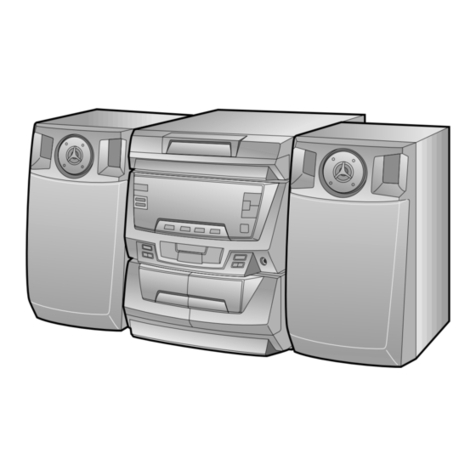
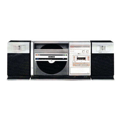
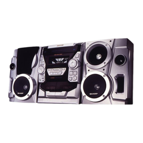
Sharp GF-A2Z(S) User manual

mmM
SHARI=
SERVICE
MANUAL
,
S5452G
F-A2ZSl
GF-A2Z(S)
GF-A2Z(G)
In the interests of usersafety the set should be restored to its
original condition and only parts identical to those specified be
used.
Photo:
G
F-APZ(S)
/-INDEX
TO CONTENTS
--.
Page
SPECIFICATIONS ...............................................
1
NAMESOFPARTS ..............................................
2
VOLTAGE SELECTION ...........................................
2
STRINGING OF DIAL CORD .......................................
2
DISASSEMBLY .................................................
3
BLOCKDIAGRAM ..............................................
4
TEST TAPES FOR MEASUREMENT ..................................
5
MECHANICAL ADJUSTMENT ......................................
5
CIRCUITADJUSTMENT
........................................5-7
ACPOWERSUPPLYCORD .........................................
7
NOTES ON SCHEMATIC DIAGRAM ..................................
8
WlRlNGSlDEOFP.W.BOARD
...................................
.9,10
SCHEMATIC DIAGRAM ........................................
II,12
EXPLODEDVIEW..
..........................................
13,14
REPLACEMENT PARTS LIST ....................................15-18
SPECIFICATIONS
GENERAL
Power source:
Output power:
Semiconductors:
Dimensions:
AC
110
-
127V and 220
-
240V
DC 9
V
(UM/SUM-1
or
R20
type x6)
PMPO; 15
W
(7.5
w
+
7.5
W)
(AC operation)
MPO; 8
W
(4w+4w)
(AC operation)
RMS; 4.6
W
(2.3
W
+
2.3
W)
(DC operation
10
%
distortion)
8
ICs
3 Transistors
13 Diodes
6
LEDs
Width; 550 mm
(21-5/8”)
Height; 220 mm
(8-5/8”)
TAPE RECORDER
Tape:
Frequency range:
Signal/noise ratio:
Wow and flutter:
Input impedance:
Loaded impedance:
Headphones;
External speakers;
RADIO
Frequency range:
SPEAKER
Speakers:
Impedance:
Compact cassette tape
80 Hz
-
10,000 Hz
36
dB
0.15
%
(WRMS)
External mic: 600 ohms
8
-
25 ohms
3.2
-
8 ohms
FM; 87.6 MHz
-
108
MHz
AM; 526.5 kHz
-
1606.5 kHz
SW1
;
2.3 MHz
-
7.3 MHz
SW,; 7.3 MHz
-
22 MHz
12 cm
(4-3/4”)
woofer x2
Horn type tweeter x2
3.2 ohms
Weight:
Depth; 130 mm (5-I
/8”)
3.6 kg (7.9
Ibs.)
without batteries Specifications for this model are subject to change without
prior notice.
SHARP CORPORATION
All manuals and user guides at all-guides.com
all-guides.com

FOR
A
COMPLETE DESCRIPTION OF THE OPERATION OF THIS UNIT,
PLEASE REFER TO THE OPERATION MANUAL.
1.
Built-in Microphone
2. Band Selector Switch
3.
FM
Stereo Indicator
4. Function Selector Switch
5.
Volume Control
6.
Balance Control
7. Fine Tuning Control
8.
Power Indicator
9. Sound Level Meter
10.
Tuning Control
11.
Headphones Jack
12.
Cassette Compartment
13.
Record Button
14.
Rewind Button
15.
Play Button
16.
Fast-Forward Button
17.
Stop/Eject Button
18. Graphic Equalizer Controls
19. Speaker Release Knob
20. External Speaker Terminals
21.
External Microphone Jack
22. FM/SW Telescopic Rod Antenna
23.
Battery Compartment
24. Speaker Cord Holder
25. AC Power Supply Socket
NAMES OF PARTS
1234 5 6789 1011
Figure 2-l
20
21
22 23
III
I
24 25
Figure 2-2
24
VOLTAGE
SELECTION
Before operating the unit on mains,
check
the preset voltage.
If the voltage is different from your local voltage,
adjust the
voltage as follows: Slide the AC power supply socket cover by
slightly loosing the screw to the visible indication of the side
mi
m’:1II
of your local voltage.
Figure 2-3
STRINGING
OF
DIAL
CORD
1. Turn the drum fully in the
direction@shown
in Fig. 2-4
and stretch its cord over the parts in the numerical order.
2. Then turn the tuning control shaft fully in the direction@
shown in Fig. 2-4 and fix its pointer as shown in Fig.
2-5.
Spring
with Dial Cord
(102)
451 mm
Pointer
(109)
17 mm Frame
(114)
f9
/
Figure 2-5
ing Control Shaft
Figure 2-4
All manuals and user guides at all-guides.com

DISASSEMBLY
Caution on Disassembly
Follow the below-mentioned notes when disassembling the
unit and reassembling it, to keep its safety and excellent
performance:
1. Take cassette tape out of the unit.
2. Be sure to remove the power supply plug from the wall
outlet before starting to disassemble the unit and remove
the batteries from the unit.
3. Take off nylon bands or wire holders where they need be
removed when disassembling the unit. After servicing
the unit, be sure to rearrange the leads where they were
before disassembling.
4. Take sufficient care on static electricity of integrated
circuits and other circuits when servicing.
iTEP
REMOVAL
PROCEDURE FIGURE1
sin
body
section:
1
Front cabinet
1.
Knob . . . . . . .
(A)x4
2. Battery compartment
lid
. . . . . . . , .
03)x1
3. Open the cassette
holder . . . . . . . (C)
4. Screw . . . . . . .
(D)x5
3-l
2Mechanism block 1. Screw . . . . . . .
(E)x2
2. Socket . . . . . .
(F)x2
3-3
Graphic Equalizer 1. Screw (G)x3
P.W.Board 3-2
(“1)
I
3Main P.W.Board
1.
Record interlocking
(‘1)
lever. . . . . . .
(H)xl
(‘2)
2.Socket
. . . . . .
(1)x1
4Power Bupply 1. Screw . . . . . . . (J)x~
P.W.Board 2. Battery terminal
(‘1)
spring . . . . . . .
(K)x2
I
,
paaker
section:
Front Cabinet 1. Screw , . . . . . .
(L)x5
2. Speaker Cord . .
(~)xl
3--4
-I
*I.
Each P.W.B. should be removed until the parts to be
exchanged can be removed when servicing. If the parts to
be exchanged are in the exchangeable condition, the rest
of
P.W.Bs
need not to be removed.
*2.
When taking the main P.W.B. out the unit, the P.W.B.
cannot be removed unless the every external speaker
terminal knobs located at the rear side are let down.
Front Cabinet
I
(D)x5
Figure 3-l
Graphic Equalizer P.W. Board
Figure 3-2
Vain
P.W.Board
/
F‘c7\
.
.
.
\
Pu
!
(L)‘x5
Figure 3-4
-3-
Figure 3-3
All manuals and user guides at all-guides.com

AM IF/RF ADJUSTMENT
SIGNAL GENERATOR 400 Hz, 30%, AM modulated
STEP
S;;gE
FRE-
DIAL
POINTER
A;pNy
QUENCY
SETTINGREMARKS
maximal output
7
2.25 MHz
Lowest
LS
Band
frequency
-
coverage
I
8
7.4 MHz
Highest
TC7
frequency Adjust for
maximal
9output
2.6 MHz 2.6 MHz L7
(SWl)
-
Tracking
-
10
6.0 MHz 6.0 MHz
TC4
11
Repeat steps
78,s
and 10 until no further improvement can
be made.
SW, RF
12 7.2 MHz Lowest
i-8
Band
frequency
-
coverage
13
22.5 MHz Highest TC6
frequency Adjust for
14 -maximal output
8.5 MHz 8.5 MHz L6
-
Tracking
15 19 MHz
19MHz
TC3
16
Repeat steps
12,13,14
and 15 until no further improvement can
be made.
Sweep
generator Test loop
AM/SW
1
0
pin Oscilloscope
Figure 6-l AM IF
Figure 6-2 AM RF
8$-j
To
chassis
ground
2
:
Output impedance of signal generator
generator
Ext. Electronic
Voltmeter
(TP2)
Figure 6-3 SW RF
-6-
All manuals and user guides at all-guides.com

MECHANICAL
ADJUSTMENT
l
For the details of the test tapes used for the measurement,
refer to the Table “TEST TAPES FOR MEASUREMENT”.
E.V.: Electronic Voltmeter
ITEM
JIG
ADJUSTMENT
POINTS
REMARKS
(CHECK)
Pinch
roller
pressure
Tension gauge
Pinch roller 370
*
6Og
(500
9) pressure spring
*
If the reading
is outside the
range, replace the
pressure spring of
the pinch roller.
Driving
power Tape tention
measuring
cassette
TW-2412
(More than
150
g1
Torque Torque meter
Play
TW-2111
Fast-forward
TW-2231
Rewind
l-W-2231
(Play:35
-
60 g-cm
(Fast-fo~lard:
70
-
120
g-cm)
(Rewind:
70
-
120
g-cm)
Azimuth
Tape
speed
Test tape
M-f-r-1 13C
Test tape
Ml-T-1
11
Azimuth Sine waveform
adjusting attains the
screw
maximum.
Variable resistor 3,000
f
90 Hz
on motor
r
Test Tape
MTT-
113C
o
3.2 ohmsx2
, Record/Playback
Head
Ext. Speaker
Terminal
1%ch)
Test Tape
MTT-111
Figure 5-l AZIMUTH
Ext.
Speaker
I
Playback Terminal
Mode
Frequency Counrer
Unit
GND
/
Figure 5-2 TAPE SPEED
CIRCUIT
ADJUSTMENT
(AUDIO
SECTION)
COMPACT CASSETTE TYPE
DISTORTION
DOLBY LEVEL MTT-150
CALIBRATION
i
FREQUENCY/ APPLICATION MODEL MEASUREMENT APPLICATION
LEVEL RANGE
3 kHz, -10 dB Tape speed,
Wow and flutter
check
TW-2111
lo-
1OOgcm Normal
:
Playback torque
1
1.5-1Ogcm
1
Normal
:
Back tension
I
6.3
kHz,
-10
dB
Head azimuth
8 kHz, -10 dB adjustment
lOkHz,-1OdB
TW-2121
1
lo-1OOgcm
Reverse
:
Playback torque
I
1
kHz,
-10
dB Distortion
chech
level adjustment TW-2231
1.5
-
log-cm
30
-
200 g-cm
Reverse
:
Back tension
Fast-forward, Rewind torque
Dolby B-Type Dolby NR
Tone 200 nwblm B-type level
adjustment
TW-2412
j
0-300gNormal
:
Driving power
I
TW-2422
1
0
-
3009
Reverse
:
Driving power
I
Record fre-
quency check
SETTING
POSITION
OF
WITCH
AND KNOB
ITEM
l
Volume control: Maximum
l
Balance control: Center
*Graphic equalizer control: Center
l
Function selector switch: Tape
ADJUST-
INPUT
MENT REMARKS
(CHECK)
POINT
Dscilloscop
Test Tape
MTT-118
Head
PLAY BACK Test tape
AMPLIFIER
MTT-118
-
(0.85
-
1.7V)
Figure 5-3 PLAYBACK AMPLIFIER SENSITIVITY
SENSITIVITY
TEST
TAPES FOR
MEASUREMENT
TORQUE METER FOR COMPACT CASSETTE
I
-5-
All manuals and user guides at all-guides.com

+G 0104
D
1
I
::
SW102-C
I
tB
Ix
VR501-505l81
AC
INWT
so301
T301
0
II----p
AC
110-,27”
POWER 5cvGO
HZ
TflZNSFORMER
0
/
AC
220-24pv
I
:>
ty
50,GoHr
SWIOI-A-D
:
FUNCTION SELECTOR SWITCH
L---
SW 102-A
-
J
:
RECORD/PLAYBACK SWITCH a-
SW30,
SWZOI-AwE
:
LOUDNESS SWITCH
AC/DC
SELECTOR
9”
Figure 4 BLOCK DIAGRAM
-4-
All manuals and user guides at all-guides.com
all-guides.com

FM IF/RF ADJUSTMENT
SWITCH POSITION
SIGNAL
GENERATOR
STEf
,
TEST
STAGE
I
FRE-
QUENCY
1
2
3
F
4
5
6
7
8
10.7 MHz
T2
counter-
clockwise
IF
Tl
before taking
it out of the
bobbin.
2. Adjust for
best
“IF”
High
CUNB.
frequency
Detection
T2
Adjust for best
“S” curve.
fepeat
steps
1
and 2 until no further improvement can be made,
87.1 MHz Lowest
13
Band
frequency
coverage
109 MHz Highest TC2
frequency Adjust for maximal
output.
88 MHz
88MHz
L2
Tracking 108 MHz 108 MHz
TCl
Repeat steps 4, 5and 6, 7 until no further improvement can
be made.
FM mono
1
400 Hz, 30%. FM modulated
DIAL
POINTER
A,$;y-
REMARKS
SETTING
I
I
I.
Using a minus
driver, turn
the core of
VCO FREQUENCY ADJUSTMENT
SIGNAL GENERATOR
400
Hz. 30%. FM modulated
I
(mono signal)
DIAL
FREQUENCY POINTER ADJUST- REMARKS
SETTING MENT
FM mono position FM stereo position
(unmodulated)
98 MHz at 54
dB
98 MHz
VRI
Adjust for 38.00 kHz
f
1OOH.z.
Sweep
(TP2) (TP5)
Figure 7-l FM IF
later
si
c-:---a
(See
Figure 7-4)
generator
(TP2)
Figure 7-2 FM
RF
“inns1
(See Figure 7-4)
(TP4)
Figure 7-3 VCO FREQUENCY
Rl
=
37.5 ohms
..v
-
I
”
I
r
I
L
=
‘3
onms-==CR2 =
75
ohms
To chassis
Rl
=
500hms
ground (TP2)
2
=
50
ohms<R2
=
5.
ohms
2
:
Output impedance of signal generator
Figure 7-4 FM DUMMY
AC
POWER
SUPPLY
CORD
QACCZ0059AFOO
QACCL00155AFOO
QACCZ0060AFOO
7
.-
__lll_ll___llll__-l---.----~
-.-----
---_
CYI
-___pc*
All manuals and user guides at all-guides.com

Figure 8-l ADJUSTMENT POINT
NOTES
ON
SCHEMATIC
DIAGRAM
0
Resistor:
To differentiate the units of resistors, such symbol as
K
is
used: the symbol
K
means
1000
ohm and the resistor
without any symbol is ohm-type resistor.
0
Capacitor:
To indicate the unit of capacitor, a symbol
P
is used: this
symbol
P
means micro-micro-farad and the unit of the
capacitor without such a symbol is microfarad. As to elec-
trolytic capacitor, the expression “capacitance/withstand
voltage” is used.
l
The indicated voltage in each section is the one measured
by Digital
Multimeter
between such a section and the
chassis with no signal given.
(
1:
AMmode
Marking except for
(
1:
FM mode
l
Schematic diagram and Wiring Side of
P.W.Board
for this
model are subject to change for improvement without prior
notice.
. Parts marked with
”
A
”
(
1
are important for main-
taining the safety of the set. Be sure to replace these parts
with specified ones for maintaining the safety and per-
formance of the set.
-8-
All manuals and user guides at all-guides.com

-
A
B
C
D
E
F
G
~
H
1
2
3
I
45
I
6
1
I
2
3
1
4
I
5
I
6
-9-
Figure
9
WIA
All manuals and user guides at all-guides.com

[MAIN
PWR
I
I
_--------
------
_---------
J/’
I
I
[
POWER SUPPLY
PW.B.]
’
SW3OIISClJOI
I
7
I
8
I
9
I
10
11
12
e
9 WIRING SIDE OF
P.W.BOARD
-lO-
All manuals and user guides at all-guides.com

TOP VIEW
1
23
I
4
5
I
6
A
A
6
C
BOTTOM VIEW
H
I
L
I
I
Figure 13 EXPLODED VIEW
(Mlh-lANISM)
3
I
All manuals and user guides at all-guides.com
all-guides.com

108
/
I
/,’
I
3
I
4
I
5
I
Figure 14 EXPLODED VIEW (CABINET)
-14-
All manuals and user guides at all-guides.com

REPLACEMENT PARTS LIST
“HOW TO ORDER REPLACEMENT PARTS”
To have your order filled promptly and correctly, please furnish the following information.
1. MODEL NUMBER 2. REF. NO.
3. PART NO. 4. DESCRIPTION
NOTE:
Parts marked with
“A”
are important for maintaining the safety of the set, Be sure to replace these parts with
specified ones for maintaining the safety and performance of the set.
REF.NO.
PART NO.
DESCRIPTION
INTEGRATED CIRCUITS
CODE
ICl
IC2
IC3
ICI 01
IC201
IC401
IC501
IC502
VH
iBA4402//-
1
FM Front-End,
BA4402
AF
VHiAN7224//-1
FM
IF/AM
Circuit, AN7224 AH
VHiTA7343P/-1
PLL FM Stereo Multiplex, AG
TAJ
343
P
VHiM51164U-1
Pre-Amp./REC. Amp.,
AG
M51164L
VH
iBA5406//-
1
Power Amp., BA5406 AK
VHiiR2E31//-1
Level Meter Drive, IR2E31 AF
VHiM5226P//-1
Graphic Equalizer,
M5226P
AG
VHiM5226P//-1
Graphic Equalizer,
M5226P
AG
TRANSISTORS
0103
VS2SC1815GR1
Silicon. NPN,
2SC1815
GR
AB
0701
VS2SCl815GR-1
Silicon, NPN,
2SC181
5 GR AB
0702
VS2SC1815GR-1
Silicon, NPN,
2SC1815
GR
AB
DIODES
Dl
D3
D4
D5
D6
D7
Dl 01
D102
VHDl
SS133//-1
Silicon. 1
SS133
AA
VHDl
SS21
l//-l
Silicon, 1 SS21
1
AA
VHDl
SS133//-1
Silicon, 1
SS133
AA
VHDl
SS133//-1
Silicon,
1
SSI
33 AA
VHDl
SS133//-1
Siliccn, 1
SSI
33 AA
VHDl
SSI
33//-l
Silicon, 1
SS133
AA
RH-PX1067AFZZ
LED, Red,
5-Segment
Display, AH
LT3025P
VHERDGR8JBP-1 Zener,
6.62V-6.96V/O.4W,
AB
D103
D104
D105
VHDl
SSI
33//-l
VHDI
SS133//-1
VHERDSRl
JB2-1
RD6.8JB2
Silicon, 1
SS133
Silicon,
1
SSI
33
Zener,
4.97V-5.23V.
RD5.1
Jf32
LED, Red,
LT3027P
Silicon,
S5566G
Silicon,
S5566G
Silicon,
S5566G
Silicon,
S5566G
Port of
REF.No.DlOl
AA
AA
AB
Dl
11
D301
D302
D303
D304
RH-PX1072AFZZ
VHDS5566Gll-1
VHDS5566G//-1
VHDS5566G//-f
VHDS5566G//-1
AD
AB
AB
AB
AB
D401-
Ll
I2
L3
L6
L7
L8
L9
Ll
0
LlOl
Tl
D404
COILS
RCiLA0652AFZZ
Filter, FM Band Pass
RCiLR0364AFZZ
FM RF
RCiLB0628AFZZ
FM Oscillator
RCiLA0556AFZZ
SW2
Antenna
RCiLA0689AFZZ AMlSWl
Bar Antenna
RCiLB0625AFZZ
SW2
Oscillator
RCiLB0624AFZZ
SW1
Oscillator
RCiLB0623AFZZ
AM Oscillator
VP-MK470KOOOO 47
,uH
TRANSFORMERS
RCiLi0324AFZZ
FM IF
-
AD
AA
AC
AD
AG
AC
AC
AC
AB
AC
-15-
REF.NO.
PART NO. DESCRIPTION CODE
T2
T3
T301
RCiLi0312AFZZ
FM Detector
RCiLi03lOAFZZ
AM IF
RTRNP1099AFZ.Z
Power
AC
AC
AQ
FILTERS
CFl
CF2
RFiLF0080AFZZ
Ceramic, 10.7 MHz (FM IF) AD
RFiLA0085AFZZ
Ceramic, 455 kHz (AM IF) AE
CONTROLS
TCl/2/4/7
RVC-R0083AFZZ
Variable Capacitors,
VCl --4
Tuning with Trimmers AN
TC3
TC5
TC6
TC8
vc5
VRl
VR202
VR203
VR501-
RTo-HI
072AFZZ
RTo-H1072AFZZ
RTo-HI
072AFZZ
RTo-H1072AFZZ
RVCZOO64AFZZ
RVR-M0390AFZZ
RVR-B0290AFZZ
RVR-G0080AFZZ
505
RVR-ZOl92AFZZ
Trimmer AC
Trimmer AC
Trimmer AC
Trimmer AC
Fine Tuning AE
5 kohms(B), VCO Adjustment AB
50 kohms(W), Balance AD
Control
20 kohms(K), Volume Control AF
100
kohm(W), Graphic AG
Equalizer
ELECTROLYTIC CAPACITORS
(Unless otherwise specified, electrolytic capacitors are
+20%
type.)
Cl2
Cl5
c20
C25
C26
c40
c41
C42
c44
c47
C48
c49
c74
c75
Cl00
Cl01
Cl 13
Cl14
Cl 17
Cl 18
Cl 19
Cl20
Cl21
Cl 25
Cl 34
Cl42
C207
RC-EZA336AFl
C
RC-EZA106AFl
C
RC-EZA476AFl
A
RC-EZA107AFl
A
RC-EZA475AFl
E
RC-EZAI
06AFl
C
RC-EZA335AFl
H
RC-EZA105AFl
H
RC-EZA475AFl
E
RC-EZA105AFl
H
RC-EZA105AFl
H
RC-EZA227AFl
A
RC-EZA106AFl
C
RCEZA476AFl
A
RC-EZA336AFl
C
RC-EZA334AFl
H
RC-EZA107AFl
A
RC-EZA107AFl
A
RCEZA335AFl
E
RC-EZA335AFl
E
RC-EZAI
06AFl
C
RCGZA477AFOJ
RCEZA476AFl
A
RC-EZAI
07AFl
A
RC-EZA476AFl
C
RC-EZA226AFl
C
RC-EZAl05AFl
H
33
pF,
16V
10
/.LF.
16V
47
P-F.
1OV
100
/.LF,
1OV
4.7
,uF,
25V
10
/LF.
16V
3.3
@F,
50V
1 PF.
50V
4.7
PF.
25V
1
pF,
50V
1 pF, 50V
220
/LF,
1OV
10
pF,
l6V
47
pF,
1OV
33
pF,
16V
0.33 PF, 50V
100
,uF,
1OV
100
PF.
1OV
3.3
P-F,
25V
3.3
/..LF.
25V
10
/.LF,
16V
470
,uF,
6.3V
47
pF,
IOV
100
,uF.
1OV
47
,LLF,
16V
22
pF,
16V
1
pF,
50V
AB
AB
AB
AB
AB
AB
AB
AB
AB
AB
AB
AB
AB
AB
AB
AB
AB
AB
AB
AB
AB
AB
AB
AB
AB
AG
AB
All manuals and user guides at all-guides.com

REF.NO.
PART NO.
C208
c211
c212
C213
C214
c215
C216
c219
c220
c221
C402
c403
c404
c405
c500
c501
C502
c503
c504
c509
c510
c513
c514
c517
C518
c701
RC-EZAl05AFl
H
RC-EZA336AFl
C
RC-EZA336AFl
C
RC-EZA476AFl
A
RC-GZA337AFl
C
RC-EZA476AFl
A
RC-EZA476AFl
A
RC-EZA227AFl
A
RC-EZA227AFl
A
RC-EZI 267AFZZ
RC-EZA475AFl
E
RC-EZA107AFl
C
RC-EZA104AFl
H
RC-EZ1289AFZZ
RC-EZA476AFl
C
RC-EZA226AFl
C
RC-EZA226AFl
C
RC-EZAI
05AFl
H
RC-EZAI
05AFl
H
RC-EZA105AFl
H
RC-EZA105AFl
H
RC-EZA105AFl
H
RC-EZAI
05AFl
H
RC-EZA334AFl
H
RC-EZA334AFl
H
RC-EZA475AFl
E
DESCRIPTION
1 PF. 50V
33PF.
16V
33
pF,
16V
47
~.LF,
1OV
330
ELF,
16V
47
pF,
1OV
47
/.LF,
1OV
220
PF.
IOV
220
PF.
1OV
2200 pF, 16V
4.7
/.LF,
25V
100
,uF,
16V
0.1
/.LF,
50V
1 PF, 50V
47
/.LF,
16V
22
pF,
16V
22
/.LF,
16V
1
pF,
50V
1
pF,
50V
1 pF, 50V
1
/LF,
50V
1
pF,
50V
1 PF. 50V
0.33
pF,
50V
0.33
pF,
50V
4.7
pF,
25V
CODE
AB
AB
AB
AB
AC
AB
AB
AB
AB
AE
AB
AB
AB
AC
AB
AG
AG
AB
AB
AB
AB
AB
A0
A0
AB
AB
CAPACITORS
(The terms CM, SC and
STused
here indicate thetypes of capacitorceramictype,
Semiconductor type and
styrol
type.)
(Tubular-shapedtypechip capacitoris identified bythesymbol
MFofthe
part No.
VC..MF....;
this MF does not mean the lead wire.)
Cl
c2
c3
c4
C6
c7
C8
c9
Cl0
Cl1
Cl3
Cl4
Cl9
c21
c22
C23
C24
C28
c29
c30
c43
c45
C46
C61
C62
C63
C64
C66
C67
C68
c70
c71
c73
C76
VCCSMFl
HL180J
18pF,
5OV,
&5%,
CMAA
VCl-YMFl
HV472K
0.0047 PF. 5OV.
flO%,
SC AA
VClYMFl
HV472K
0.0047
pF,
5OV,
+lO%,
SC AA
VCCCMFl
HH220J
22
pF(CH),
5OV.
+-5%,
CMAA
VCCCMFI
HHISOJ
15 pF(CH), 5OV,
+5%,
CMAA
VCCCPUI
HH8ROD 8
pF(CH),
5OV,
+0.5
pF,
CMAA
VCTYMFl
HVl52K
0.0015
pF,
5OV.
+I
0%. SC AA
VCCRMFI
HHl5OJ
15pF(RH), 5OV,
rt5%,
CM AA
VCCCMFI
HH2R2C
2.2 pF(CH), 5OV,
+0.25
pF, AA
CM
VCCCMFl
HH2R2C
2.2 pF(CH), 5OV,
kO.25,
pF AA
CM
VCTYMFlCY223N
0.022
,uF,
16V.
-c30%,
SC AA
VCTYMFI
CY223N
0.022 PF.
16V.
+30%,
SC AA
VCTYMFI
EXIOBN
0.01 pF,
25V,
f30%,
SCAA
VCTYMFlCY223N
0.022
E”F,
16V.
+30%,
SC AA
VCTYMFlCY223N
0.022
pF,
16V.
+-303/o,
SC AA
VCKYBTl
HB221
K
220
pF,
5OV,
flO%,
CMAA
VCTYMFlCY223N
0.022 pF,
16V.
+30%,
SC AA
VCCSMFI
HL470J
47
pF,
5OV,
f5%,
CMAA
VClYMFlCY223N
0.022
pF,
16V.
f30%,
SC AA
VCTYMFl
CY223N
0.022
pF,
16V,
t30%,
SC AA
VCQSMA’l
HLl02J
0.001
@F,
5OV,
+5%,
STAB
VCTYMFl
NY333N
0.033 pF,
12V,
f30%,
SC AA
VCTYMFl
NY333N
0.033
pF,
12V,
+-30%.
SC AA
VCCCMFl
HH6R8D
6.8
pF(CH),
5OV,
+0.5
pF, CM AA
VCCSMFl
HL4R7C 4.7 pF, 5OV.
+0.25
pF,
CMAA
VCCCMFl
HH120J
12
pF(CH),
5OV,
f5%,
CMAA
VCTYMFl
HVI
52K 0.0015
I.IF,
5OV,
+lO%,
SC AA
VCCCMFl
HHlOOJ
10
pF(CH),
5OV,
?5%,
CMAA
VCTYMFl HB331
J
330 pF, 5OV,
+5%,
CM AA
VCCSMFl
HL330J
33
pF,
5OV, ?5%. CM AA
VCCCMFl
CH8R2D
8:2
pF(CH),
5OV,
kO.5
pF,
AA
CM
VCTYMFl
HV472K
0.0047
pF,
5OV.
+lO%,
SC AA
VCTYMFlCY223N
0.022 pF,
16V.
+-30%,
SC AA
VCTYMFl
HVI
52K 0.0015
pF,
5OV,
*lo%,
SC AA
REF.NO.
PART NO.
DESCRIPTION CODE
c77
c79
Cl03
Cl04
Cl05
Cl06
Cl07
Cl08
Cl11
Cl12
Cl 22
Cl 24
Cl 29
Cl 30
Cl 31
Cl 32
Cl 35
Cl 36
Cl 37
Cl 38
Cl39
Cl40
Cl41
c209
c210
C217
C218
c222
c301
C302
c304
c401
c505
C506
c507
C508
c511
C512
c515
C516
c519
C520
C521
C522
C523
C524
C525
C526
C527
C52B
c529
c530
VCCCMFI
HH2R7C
2.7
pF(CH),50V.+0.25
pcCM
AA
VCTYMFlCY223N
0.022
pF,
16V,
+30%,
SC AA
VCCSMFI
HLlOl
J
100
pF,
5OV,
f5%,
CMAA
VCCSMFl
HLl 01
J
100
pF,
5OV.
+5%,
CMAA
VCKYMFl
HB102K
0.001
pF, 5OV,
flO%,
CM AA
VCKYMFl
HB102K
0.001
P-F,
5OV.
flO%,
CM AA
VCTYMFl
HV222K
0.0022 pF, 5OV.
&IO%,
Sd
AA
VCTYMFI
HV222K
0.0022
@F.
5OV,
tlO%.
SC AA
VCTYPAl
EX683K
0.068
pF,
25V.
,I
0%. SC AB
VCTYPAI
EX683K
0.068
pF,
25V.
&IO%,
SC AB
VCTYMFl
EX103N
0.01
pF,
25V.
+30%,
SCAA
VCTYMFlCY223N
0.022
pF,
16V.
f30%,
SC AA
VCKYMFl
HB821
K
820
pF,
50V.
+lO%,
CMAA
VCKYMFl
HB821
K
820
pF,
50V.
-tlO%,
CMAA
VCCSMFI
HL470J
47
pF.
5OV.
+5%,
CMAA
VCCSMFI
HL470J
47
pF,
50V.
+5%,
CMAA
VCKYBTI HB151
K
150
pF,
5OV.
-+I
0%. CMAA
VCKYBTl
HB151
K
150
pF,
5OV.
flO%,
CMAA
VCl-YMFl
CY223N
0.022 pF,
16V.
+30%,
SC AA
VCTYMFlCY223N
0.022
pF,
16V.
f30%,
SC AA
VCKYBTI HB221
K
220
pF,
5OV.
+I
0%,
CMAA
VCTYATI
EX103M
0.01
,uF,
25V,
+20%,
SCAA
VCTYATI
CY223N
0.022pF,
16V.
f30%,
SC AA
VCKYMFl
HB102K
0.001 pF,
50V.
&IO%,
CM AA
VCKYMFI
HB102K
0.001 pF, 5OV.
+lO%,
CM AA
VCTYPAI
EX104K
0.1
~.LF,
25V.
&IO%,
SCA8
VCTYPAI
EXl04K
0.1
ELF,
25V.
+lO%,
SCAB
VCTYPVlEX104.l
0.1
pF,
25V,
+lO%,
SC AA
VCKZPAl
HF1022
0.001
pF,
50V.
+80-20%.
AA
CM
VCKZPAl
HF102Z
0.001
pF, 5OV.
+80-20%.
AA
CM
VCKZPAl
HF102Z
0.001 PF, 5OV,
+BO-20%,
AA
CM
VCKYBTI
HB102K
0.001
pF, 5OV,
&IO%,
CM AA
VCKYPAI
HB102K
0.001
PF. 5OV.
&IO%,
SC AA
VCKYPAlHB102K
0.001
PF. 5OV.
tlO%,
SC AA
VCKYPAl
HBl02K
0.001
PF. 5OV,
flO%,
SC AA
VCKYPAl
HB102K
0.001
,uF,
5OV,
flO%,
SC AA
VCKYPAl
EX393K
0.039 pF,
25V,
+lO%,
SC AA
VCKYPAl
EX393K
0.039
pF,
25V,
flO%,
SC AA
VCKYPAl
EX723K
0.012 pF,
25V.
&lo%,
SC AA
VCKYPAl
EX123K
0.012
pF,
25V.
+109/o. SC AA
VCKYPAl
EX392K
0.0039 pF,
25V.
+lO%,
SC AB
VCKYPAl
EX392K
0.0039 pF,
25V.
flO%,
SC AB
VCTYPAl
EX104K
0.1
pF,
25V,
210%.
SCAB
VCTYPAI
EX104K
0.1
pF,
25V,
t-10%,
SCAB
VClYPAl
HB122K
0.0012 pF, 5OV,
flO%,
CM AA
VCTYPAl
HBl22K
0.0012 PF. 5OV.
+lO%,
CM AA
VClYPAl
EX333K
0.033
pF,
25V,
&IO%,
SC AA
VCTYPAl
EX333K
0.033
pF,
25V,
-I-10%,
SC AA
VCCSPAl
HL391
J
390
pF,
5OV.
f5%,
CMAA
VCCSPAI
HL391
J
390
pF,
50V.
f5%,
CMAA
VCTYPAI EXI 03K 0.01 pF,
25V.
Cl
0%. SC AA
VCTYPAl
EX103K
0.01
pF,
25V,
&lo%,
SCAA
RESISTORS
(Unless otherwise specified, resistors are
1/6W.
*5%,
carbon type.)
(Tubulartype carbon film
resistor(l/4W.
?5%)
is identified bythesyml
the part No.
VRD-MFOOOOOOO;
this MF does not mean lead wire.)
Rl
R4
R5
R6
R7
R8
R9
RlO
Rl
1
VRD-ST2CD391
J
VRD-ST2CD824J
VRD-ST2CD182J
VRD-MF2EE822J
VRD-ST2CD272J
VRD-ST2CD680J
VRD-MF2EE471
J
VRD-ST2CD152J
VRD-MF2EE471
J
390 ohms
820 kohms
1.8 kohms
8.2 kohms
2.7 kohms
68 ohms
470 ohms
1.5
kohms
470 ohms
301
MF of
AA
AA
AA
AA
AA
AA
AA
AA
AA
-16-
All manuals and user guides at all-guides.com

REF.NO.
PART NO.
DESCRlF’TlON CODE REF.NO.
R41
VRD-MF2EE102J
1 kohm AA
R42
VRD-MF2EEl03J
10 kohm AA
R43
VRD-ST2CD224J
220 kohms AA
R44
VRD-ST2CD471
J
470 ohms AA
R45
VRD-MF2EE332J
3.3 kohms AA
R46
VRD-MF2EE332J
3.3 kohms AA
R47
VRD-MF2EE102J
1 kohm AA
R48
VRPST2CD102J
1
kohm AA
R50
VRD-MF2EE821
J
820 kohms AA
R51
VRD-MF2EE477
J
470 ohms AA
R61
VRD-MF2EElOl
J
100 ohm AA
R63
VRD-MF2EE470J
47 ohms AA
R65
VRD-MF2EElOl
J
100
ohm AA
RlOO
VRD-ST2CD102J
1 kohm AA
RlOl VRD-ST2CD102J
1 kohm AA
R103
VRD-ST2CD562J
5.6 kohms AA
R105
VRD-MF2EEl82J
1.8 kohms AA
R109
VRD-MF2EE103J 10
kohm AA
RllO
VRD-MF2EE103J
10 kohm AA
Rlll
VRD-MF2EElOl
J
100 ohm AA
R112
VRD-MF2EElOl
J
100
ohm AA
Rl13
VRD-ST2CD222J
2.2 kohms AA
Rl
14
VRD-MF2EE222J
2.2 kohms AA
R117
VRD-MF2EE153J
15 kohms
AA
RI18
VRD-MF2EE153J
15 kohms AA
R119
VRD-MF2EE473J
47 kohms AA
R120
VRD-MF2EE473J
47 kohms AA
RI 25
VRD-MF2EEl5OJ
7
5 ohms AA
R126
VRD-MF2EE15OJ
15 ohms AA
RI27
VRD-ST2CD182J 1.8
kohms AA
R128
VRD-MF2EE182J
1.8 kohms AA
R129
VRD-MF2EE473J
47 kohms AA
R130
VRD-MF2EE473J
47 kohms AA
R135
VRD-MF2EE102J
1
kohm AA
R143
VRD-MF2EE473J
47 kohms AA
RI44
VRD-MF2EE473J
47 kohms AA
R147
VRD-MF2EE125J
1.2 Mohms AA
RI48
VRD-ST2CD470J
47 ohms AA
R149
VRD-MF2EE333J
33 kohms AA
R150
VRDST2CD102J
1
kohm AA
R201
VRD-MF2EE472J
4.7 kohms AA
R202
VRD-MF2EE472J
4.7 kohms AA
R203
VRD-ST2CD103J
10 kohm AA
R204
VRD-ST2CDlOBJ
10 kohm AA
R207
VRD-MF2EE221
J
220 ohms AA
R208
VRD-MF2EE221
J
220 ohms AA
R209
VRDST2CDl
ROJ
1 ohm AA
R210
VRD-ST2CDl
ROJ
1 ohm AA
R211
VRD-MF2EEl51
J
150
ohms AA
R212
VRD-MF2EE151
J
150 ohms AA
R401
VRD-ST2CD563J
56 kohms AA
R402
VRD-ST2CD563J
56 kohms AA
R403
VRD-ST2CD47;IJ
4.7 kohms AA
R405
VRD-ST2CD121
J
120 ohms AA
R406
VRD-MF2EE560J
56 ohms AA
R407
VRD-MF2EE822J
8.2 kohms AA
R408
VRDMF2EE822J
8.2 kohms AA
R409
VRD-ST2CD332J
3.3 kohms AA
R501
VRD-RZ2EE102J
1 kohm AA
R502
VRD-RZ2EE102J
1 kohm AA
R601
VRD-MF2EE393J
39 kohms AA
R602
VRD-MF2EE393J
39 kohms AA
R603
VRD-MF2EE821
J
820 ohms AA
R701
VRD-ST2CD472J
4.7 kohms AA
R702
VRD-ST2CD472J
4.7 kohms AA
CNPl
CNSI 01
CNS102
CNS103
CNPl
01
CNP102
CNP103
CORl
JlOl
J107
J109
Ml
A
so301
SPl
SP2
SP3
SP4
SW1
SW1 01
SW1 02
SW301
SW401
1
2
3
4
5
6
7
8
9
14
15
16
17
18
19
20
21
22
23
24.
25
26
27
28
29
30
31
32
VRD-MF2EEOOOC 0 ohm,
1/4W,
f0.25 ohms, AA
Jumper
33
34
35
-17-
PART NO.
DESCRIPTION
CIRCUIT PARTS
CODE
QCNCM6599AFZZ
6Pin
PlugAC
QCNW-2435AFZZ
3Pin Socket Assembly AE
QCNW-2436AFZZ 7Pin Socket Assembly AE
QCNW-2458AFZZ 2Pin Socket Assembly AC
QCNCMI
36CAFZZ
3Pin
PlugAB
QCNCM588GAFZZ
7 Pin Plug AB
QCNCM095BAFZZ
2Pin Plug AB
RCoRF0053AFZZ
CoreAA
QJAKEOI
15AFZZ
Jack, EXT. Microphone AC
QJAKJO133AFZZ
Jack, Headphones AF
QTANZ0468AFZZ
Terminal, EXT. Speaker AE
RMoTV0164AFOl
Motor witii Pulley AU
QS6CE0595AFZZ
Socket, AC Power Supply
AG
(with AC/DC Selector
Swatch)
VSPOO12PB71 SA Speaker, Woofer, Left AM
VSPOO12PB71 SA Speaker, Woofer, Right AM
RALMB0057AFZZ
Speaker, Ceramic Tweeter, AC
Left
RALMB0057AFZZ
Speaker, Ceramic Tweeter, AC
Right
QSW-00197AFZZ
Switch, LeverAL
QSW-00196AFZZ
Switch, Lever AG
QSW-S0428AFZZ
Switch, Slide AF
Switch, Part of SO301
-
QSW-FO136AFZZ
Switch, Skeleton AD
QCNW-2442AFZZ
Cord, Speaker AE
MECHANICAL PARTS
JKNBR0450AFSB
Button, Record, Rewind, Play, AF
Fast-Forward
JKNBR0451 AFSB Button, Stop/Eject AF
LANGFO867AFZZ
Bracket, Flywheel AC
LANGF0868AFFW
Bracket, Motor AC
LBSHZ0086AFZZ
Cushion, Motor AA
Main Chassis Assemble
-
LCHSS0204AFFW
Plate, Head Base AC
LDAiH0063AFOO
Head Base AB
LRTNP0058AFZZ
Retainer, Lever AA
MLEVFl636AFFW
Lever, Record AC
MLEVF1637AFFW
Lever, Cassette Holder Eject AB
MLEVF1638AFFW
Lever, Automatic Shut-Off AB
MLEVP0433AFZZ
Chip, Sensor AA
MLEVP0527AFOO
Lever, Erase Prevention AA
MLEVP0538AFZZ
Lever, Fast-Forward/Rewind AF
Gear
MLEVP0539AFOO
Lever, Lock Release
A0
MLEVP0540AFOO
Lever, Cassette Holder Lock AB
MLEVP0541 AFOO Lever, Lock
A0
MSPRC0456AFFJ
Spring, Head Azimuth Adjust AA
MSPRC0457AFFJ
Spring, Back Tension AA
MSPRC0497AFFJ
Spring, Flywheel AC
MSPRC0467AFFJ
Spring, Button AA
MSPRC0468AFFJ
Spring, Playback Idler AA
MSPRC0489AFFJ
Spring, Back Tension AA
MSPRD0570AFFJ
Spring, Pinch Roller AA
MSPRPO370AFFW
Sprtng,
Plate Type, Cassette AA
Retaining
MSPRTI
076AFFJ
Spring, Fast-Forward/Rewind AA
Gear Lever
MSPRTI
077AFFJ Spring, Lock Lever, Head Base AA
Plate, Record Lever
MSPRTl078AFFJ
Spring, Lock Release Lever AA
NBLTK0296AFOO Belt, Flywheel Drive AB
NBLTKQ297AFOO Belt, Fast-Forward/Rewind AB
Roller
All manuals and user guides at all-guides.com

REF.NO.
PART NO.
36
NDAiROl86AFOO
37
NDAiRO187AFZZ
38NFLYCO121 AFZZ
39
NGERHOl49AFOO
40
NiDR-0089AFZZ
41
NRoLY0065AFZZ
42
NSFTT0308AFFD
43
PGiDMOl
1
SAFOO
44
PGiDMOl20AFZZ
45
RHEDAOl
OZAFZZ
46
RHEDHOI
36AFZZ
47
LSLVMOl78AFFD
48
LHLDWl075AFZZ
49
PCUSS0249AFOO
501 LX-BZ0451 AFFD
502
LX-HZ0142AFFD
503
LX-WZI
076AFOO
504
LX-WZ1086AFZZ
505
XBPSD20W08000
506
XHPSD26P04000
507 XHPSD26P23000
508
XWHJZZI
-05040
509
XWHJZ23-05044
510
XWHSD21-05065
101
101
pm-
101-2
101-Z
101-3
101-3
101-4
AlOl-5
102
103
103
104
i‘
R
104
105
105
106
106
107
107
108
108
109
110
110
111
DESCRIPTION CODE
Turntable. Supply AB
Turntable, Take-Up AE
Flywheel AF
Gear, Fast-Forward AA
idler, Playback AD
Pinch Roller Assembly AE
Shaft, Button AC
Guide, Left Side AC
Gutde,
Right Side AC
Head, Erase AE
Head, Record/Playback AM
Sleeve AD
Nylon Band, 60 mm AA
Cushion AB
Screw, 2mm Dia. X6mm AA
Screw, 2mm Dia. X
9mm
AA
Washer AA
Stop Washer,
1.5mm
Dia.
x
AA
3.5 mm Dia. X
0.5mm
Screw, 2mm Dia. X8mm AA
Screw,
2.6mm
Dia. X4mm AA
Screw,
2.6mm
Dia. X23mm AA
Polyslider Washer, AA
2.1
mm Dia. X4mm Dia.
X
0.5mm
Polyslider Washer, AA
2.3mm
Dia. X
4.4mm
Dia.
X
0.5mm
Steel Washer, 2.1 mm Dia. AA
X
6.5mm
Dia. X
0.5mm
CABINET PARTS
CCAB-1324AFOl
Front Cabinet Assembly (S) AX
CCAB-1324AF03
Front Cabinet Assembly (G) AX
Cabinet, Front
-
HDALPD571 AFSA Plate, Dial (S) AH
HDALP0571
AFS8
Plate, Dial (G) AH
HDECPOl87AFSB
Decoration Plate, Mechanism AB
(S)
HDECPOl 87AFSC Decoration Plate, Mechanism AB
((3
PCUSUOZSOAFZZ Cushion, Built-In Microphone AA
PFLT-061 OAF00 Felt, Front Cabinet AA
CSPRT1029AF07
Spring, with Dial Cord AC
GCABAl897AFSB
Cabinet, Front, Speaker (S)
AQ
GCABA1897AFSC
Cabinet, Front, Speaker (G) AQ
GCABB1897AFSB
Cabinet, Rear, Speaker, Left
AQ
(S)
GCABB1897AFSC
Cabinet, Rear, Speaker, Left
AQ
(‘3
GCABBI
898AFSB Cabinet, Rear, Speaker, Right
AQ
(9
GCABBl898AFSC
Cabinet, Rear, Speaker, Right
AQ
(G)
GCABBlS31
AFSA Cabinet, Rear (S) AT
GCABBl931
AFSB Cabinet, Rear (G) AT
GFTAB1158AFSA
Lid, Battery Compartment (S) AE
GFTAB1158AFSA
Lid, Battery Compartment (G) AE
GFTAC1395AFSB
Holder, Cassette (S) AK
GFTACI
395AFSC Holder, Cassette (G) AK
HSSNDO340AFSA
Pointer
AC
JHNDPl058AFSB
Handle (S) AM
JHNDP1058AFSD
Handle (G) AM
JKNBKO33OAFSA
Knob, Band Selector, Function AB
Selector
REF.NO.
PART NO.
DESCRIPTION CODE
112 JKNBK0331 AFSB
113
JKNBN0542AFSB
114
JKNBZ0368AFSA
115
LHLDFI 307AFSA
116 LHLDF13 11 AFSC
116 LHLDFI 311 AFSD
117
MLiFPO034AFZZ
118
MSPRC0472AFFJ
119
MSPRC0473AFFJ
120
MSPRC0474AFFJ
121
MSPRD0590AFFJ
122
MSPRZ0071
AFFJ
123
NDRM-0200AFZZ
124
NSFTDO244AFZZ
126
PCUSS0244AFZZ
127 PFLT-0518AFOO
128
QANTROl
11 AFZZ
129
QTANZO184AFFW
130 RMiCCOOSl AFZZ
132 PFLT-0638AFZZ
134
HiNDP1079AFSA
134
HiNDPl080AFSA
133
HiNDPl095AFSA
133
HiNDP1095AFSB
136
JKNBK0334AFSA
137
GCoVH1179AFSK
137
GCoVHl179AFSH
601 LX-CZOO17AFZZ
602 XBPSD26PO8JOO
603
XCBSD30PlOOOO
604
XCBSD30P12000
605
LX-BZ0308AFFD
606
LX-BZ0286AFFF
607
XNEBZZO-16000
Knob, Volume, Balance AC
Control
Knob, Tuning Control AC
Knob, Graphic Equalizer AD
Frame AE
Holder, Graphic Equalizer (S) AF
Holder, Graphic Equalizer (G) AF
Damper, Cassette Holder
AC
Spring, Battery,
-
AC
Spring, Battery.
+
AB
Spring, Battery.
i-l-
A8
Spring, Cassette Holder AA
Lever, Record Interlocking
A8
Drum
AC
Shaft, Tuning Control AB
Cushion, Speaker AA
Felt, Cabinet, Bottom
AC
Rod Antenna AM
Terminal, Rod Antenna AB
Microphone, Built-In AF
Felt, Speaker Cabinet AA
Plate, Specifications (S) AB
Plate, Specifications (G) AB
Label, Warning (S) AB
Label, Warning (G) A8
Knob, Fine Tuning Control AE
Cover, AC Power Socket
(S)
AB
Cover, AC Power Socket (G)
AB
Taptite Screw, 3mm Dia. AA
X25mm
Screw,
2.6mm
Dia. X8mm AA
Screw, 3mm Dia. X1Omm AA
Screw, 3mm Dia.
x
12mm AA
Screw, Power P.W.Borad AA
Screw, Voltage
SeiectorCover
AA
Nut,
$2
X1.6mm AA
ACCESSORIES/PACKING PARTS
QACCL0055AFOO
QACCZ0059AFOO
QPLGA0251AFZZ
QACCZ0060AFOO
SPAKAll97AFZZ
SPAKA1198AFZZ
SPAKAl
1
SSAFZZ
SPAKC2979AFZZ
SPAKC2980AFZZ
SSAKAOOl BAFZZ
SPAKP0538AFZZ
SSAKAOO35AFZZ
SPAKP0537AFZZ
TCAUAOI
78AFZZ
TGANE1121
AFZZ
TGANEI
124AFZZ
TiNSZ0687AFZZ
TLABZOI 35AFZZ
UBATUOOOSAGZZ
TLABZ0587AFZZ
AC Power Supply Cord AM
AC Power Supply Cord AG
Adaptor, AC Power Supply AE
Cord
AC Power Supply Cord AK
Packing Add. (Left) AE
Packing Add. (Right) AE
Packing Add., Speaker AD
Packing, Case (S) AH
Packing Case (G) AH
Polyethylene
Bag,
AC Power AA
Supply Cord
Polyethylene Bag, Speaker AA
Polyethylene Bag, Operation AA
Manual
Polyethylene Bag, Unit AB
Caution Label AA
Warranty Card For PX
AC
Warranty Cord For SCA AC
Operation Manual AH
Label EGC AB
Buttery AC
Label, Special Feature, AC
Speaker
1
D8503-150H.IY
/
Writer and Editor: Engineering Administration Section of Audio Systems Group, Sharp Corp.
Printed in Japan
All manuals and user guides at all-guides.com
all-guides.com
Other manuals for GF-A2Z(S)
1
This manual suits for next models
1
Table of contents
Other Sharp Stereo System manuals

Sharp
Sharp cd-mpx880 User manual

Sharp
Sharp CD-XP120 User manual

Sharp
Sharp CD-RW5000 User manual

Sharp
Sharp XL-B715D User manual

Sharp
Sharp XL-55H User manual

Sharp
Sharp XL-MP10H User manual

Sharp
Sharp QT-CD180 User manual

Sharp
Sharp CD-MPS777H User manual

Sharp
Sharp SD-EX220H User manual

Sharp
Sharp XL-E1H User manual

Sharp
Sharp CD-BK250W User manual

Sharp
Sharp XL-UH220H User manual

Sharp
Sharp XL-1000H User manual

Sharp
Sharp CD-E700 User manual

Sharp
Sharp XL-HP505 User manual

Sharp
Sharp SD-CX1W User manual

Sharp
Sharp QT-95H User manual

Sharp
Sharp XL-DV60H User manual

Sharp
Sharp CD-SW330 User manual

Sharp
Sharp CP-BA1600 User manual