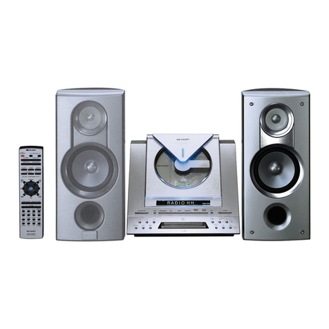
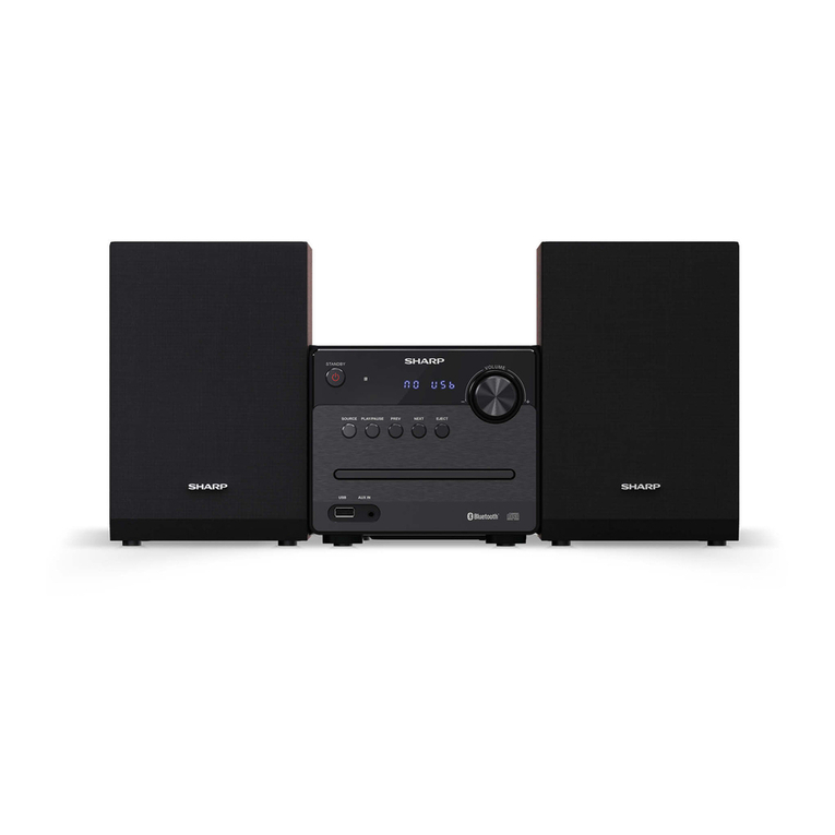
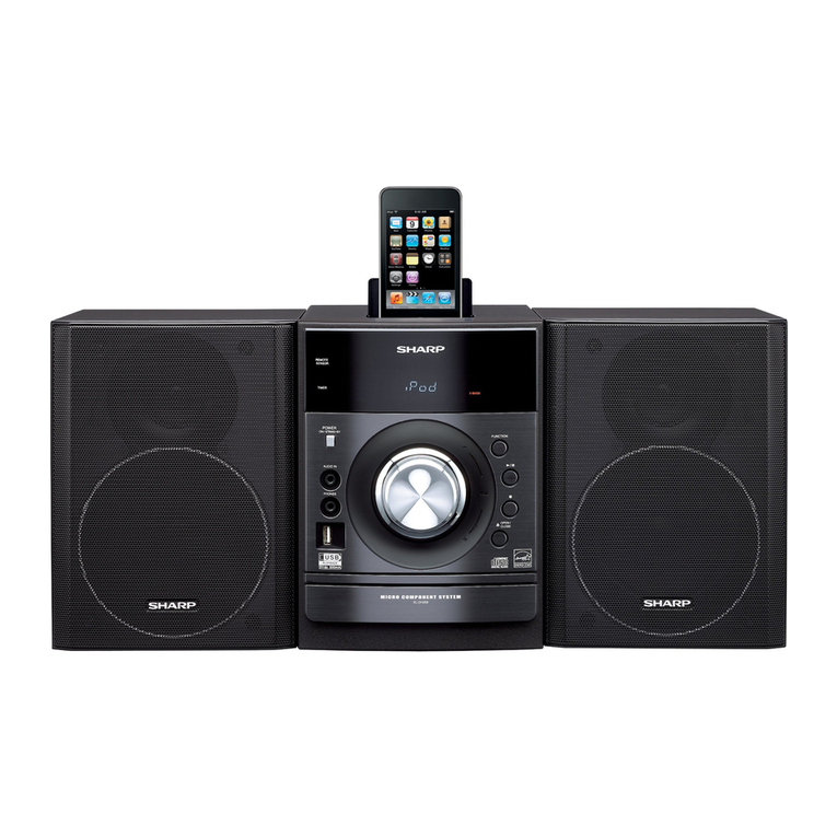
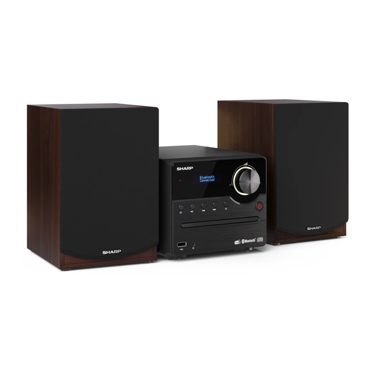
Sharp XL-MP100H User manual

SERVICE MANUAL
XL-MP100H
No. S5431XLMP100H
MICRO COMPONENT SYSTEM
XL-MP100H
MODEL
SHARP CORPORATION
CONTENTS
This document has been published to be used
for after sales service only.
The contents are subject to change without notice.
CHAPTER 1. GENERAL DESCRIPTION
[1] SAFETY PRECAUTION FOR SERVICE
MANUAL........................................................1-1
[2] IMPORTANTSERVICENOTES(FORU.K.
ONLY) ............................................................1-1
[3] SPECIFICATIONS ......................................... 1-2
[4] NAMES OF PARTS........................................1-3
CHAPTER 2. ADJUSTMENTS
[1] ADJUSTMENT............................................... 2-1
[2] TEST MODE..................................................2-2
CHAPTER 3. MECHANICAL DESCRIPTION
[1] REMOVING AND REINSTALLING THE
MAIN PARTS .................................................3-1
[2] DISASSEMBLY..............................................3-3
CHAPTER 4. DIAGRAMS
[1] BLOCK DIAGRAM.........................................4-1
CHAPTER 5. CIRCUIT DESCRIPTION
[1] WAVEFORMS OF CD CIRCUIT .................... 5-1
[2] VOLTAGE.......................................................5-2
CHAPTER 6. CIRCUIT SCHEMATICS AND PARTS
LAYOUT
[1] NOTES ON SCHEMATIC DIAGRAM............6-1
[2] TYPES OF TRANSISTOR AND LED............6-1
[3] WIRING SIDE OF PWB/SCHEMATIC DIA-
GRAM............................................................6-2
CHAPTER 7. CD CLEANER
[1] When the CD does not function.....................7-1
CHAPTER 8. OTHERS
[1] FUNCTION TABLE OF IC .............................8-1
[2] LCD DISPLAY .............................................8-12
Parts Guide
XL-MP100H Micro Component System consisting of XL-
MP100H (main unit) and CP-MP100H (speaker system).
•
In the interests of user-safety the set should be restored to its original
condition and only parts identical to those specified be used.
•
Note for users in U.K.
Recording and playback of any material may require consent which
SHARP is unable to give. Please refer particularly to the provisions of
Copyright Act 1956, the Dramatic and Musical Performers Protection
Act 1956, the Performers Protection Acts 1963 and 1972 and to any
subsequent statutory enactments and orders.
(Except for U.K.)

XL-MP100H
1 – 1
AudioXL-MP100HService ManualXLMP100HMarketE
CHAPTER 1. GENERAL DESCRIPTION
[1] SAFETY PRECAUTION FOR SERVICE MANUAL
Precaution to be taken when replacing and servicing the Laser Pickup.
The AEL (Accessible Emission Level) of Laser Power Output for this model is specified to be lower than Class 1 Requirements. However, the follow-
ing precautions must be observed during servicing to protect your eyes against exposure to the Laser beam.
1) When the cabinet has been removed, the power is turned on without a compact disc, and the Pickup is on a position outer than the lead-in posi-
tion, the Laser will light for several seconds to detect a disc. Do not look into the Pickup Lens.
2) The Laser Power Output of the Pickup inside the unit and replacement service parts have already been adjusted prior to shipping.
3) No adjustment to the Laser Power should be attempted when replacing or servicing the Pickup.
4) Under no circumstances look directly into the Pickup Lens at any time.
5) CAUTION - Use of controls or adjustments, or performance of procedures other than those specified herein may result in hazardous radiation
exposure.
[2] IMPORTANT SERVICE NOTES (FOR U.K.
ONLY)
Before returning the unit to the customer after completion of a repair or
adjustment it is necessary for the following withstand voltage test to be
applied to ensure the unit is safe for the customer to use.
Setting of Withstanding Voltage Tester and set.
VAROITUS! LAITTEEN KÄYTTÄMINEN MUULLA KUIN TÄSSÄ
KÄYTTÖOHJEESSA MAINITULLA TAVALLA SAATTAA
ALTISTAA KÄYTTÄJÄN TURVALLISUUSLUOKAN 1
YLITTÄVÄLLE NÄKYMÄTTÖMÄLLE LASERSÄTEILYLLE.
VARNING - OM APPARATEN ANVÄNDS PÅ ANNAT SÄTT ÄN
I DENNA BRUKSANVISNING SPECIFICERAS. KAN
ANVÄNDAREN UTSÄTTAS FÖR OSYNLIG LASER-
STRÅLNING, SOM ÖVERSKRIDER GRÄNSEN FÖR
LASERKLASS 1.
ADVERSEL-SYNLIG OG USYNLIG LASERSTRÅLING VED ÅBNING.
SE IKKE IND I STRÅLEN-HELLER IKKE MED OPTISKE INSTRUMENTER.
VARO! AVATTAESSA OLET ALTTIINA NÄKYVÄLLE JA NÄKYMÄTTÖMÄLLE
LASERSÄTEILYLLE ÄLÄ TUIJOTA SÄTEESEEN ÄLÄKÄ KATSO SITÄ
OPTISEN LAITTEEN LÄPI.
VARNING-SYNLIG OCH OSYNLIG LASERSTRÅLNING NÄR DENNA
DEL ÄR ÖPPNAD. STIRRA EJ IN I STRÅLEN OCH BETRAKTA EJ
STRÅLEN GENOM OPTISKT INSTRUMENT.
Laser Diode Properties
Material: GaAIAs
Wavelength: 780 nm
Emission Duration: continuous
Laser Output: max. 0.6 mW
Set name set value
Withstanding Voltage Tester
Test voltage 4,240 VPEAK
3,000 VRMS
Set time 6 secs
Set current (Cutoff current) 4 mA
Unit
Judgment
OK: The “GOOD” lamp lights.
NG: The “NG” lamp lights and the buzzer sounds.
PROBE
AC
OUT
UNIT
SHORT-CIRCUIT
AC POWER
SUPPLY CORD
CONNECT THE PROBE
TO GND OF CHASSIS
SCREW
WITHSTANDING
VOLTAGE TESTER

XL-MP100H
1 – 2
[3] SPECIFICATIONS
FOR A COMPLETE DESCRIPTION OF THE OPERATION OF THIS UNIT, PLEASE REFER
TO THE OPERATION MANUAL.
Except for U.K.
■General
■Amplifier
■Tuner
■CD player
■Cassette deck
■Speaker
Power source AC 230 V, 50 Hz
Power
consumption
Power on: 107 W
Power stand-by: 0.6 W
Dimensions Width: 160 mm (6-5/16")
Height: 228 mm (9")
Depth: 248 mm (9-13/16")
Weight 4.2 kg (9.3 lbs.)
Output power PMPO: 300 W (total)
MPO: 150 W (75 W + 75 W) (DIN 45 324)
RMS: 100 W (50 W + 50 W) (DIN 45 324)
RMS: 75 W (37.5 W + 37.5 W) (DIN 45 500)
Output terminals Speakers: 6 ohms
Headphones: 16 - 50 ohms
(recommended: 32 ohms)
CD digital output (optical)
Input terminals Video/Auxiliary (audio signal): 500 mV/47 k
ohms
Frequency range FM: 87.5 - 108 MHz
AM: 522 - 1,620 kHz
Type Compact disc player
Signal readout Non-contact, 3-beam semiconductor laser
pickup
D/A converter 1-bit D/A converter
Frequency
response
20 - 20,000 Hz
Dynamic range 90 dB (1 kHz)
Frequency
response
50 - 14,000 Hz (normal tape)
Signal/noise ratio 50 dB (recording/playback)
Wow and flutter 0.3 % (DIN 45 511)
Type 2-way type speaker system
4 cm (1-9/16") semi dome tweeter
9 cm (3-9/16") woofer
Maximum input
power
100 W
Rated input power 50 W
Impedance 6 ohms
Dimensions Width: 132 mm (5-3/16")
Height: 228 mm (9")
Depth: 197 mm (7-13/16")
Weight 2.0 kg (4.4 lbs.)/each
For U.K.
■General
■Amplifier
■Tuner
■CD player
■Cassette deck
■Speaker
Power source AC 230 - 240 V, 50 Hz
Power
consumption
Power on: 107 W
Power stand-by: 0.6 W
Dimensions Width: 160 mm (6-5/16")
Height: 228 mm (9")
Depth: 248 mm (9-13/16")
Weight 4.2 kg (9.3 lbs.)
Output power RMS: 100 W (50 W + 50 W) (10 % T.H.D.)
RMS: 75 W (37.5 W + 37.5 W)
(0.9 % T.H.D.)
Output terminals Speakers: 6 ohms
Headphones: 16 - 50 ohms
(recommended: 32 ohms)
CD digital output (optical)
Input terminals Video/Auxiliary (audio signal): 500 mV/47 k
ohms
Frequency range FM: 87.5 - 108 MHz
AM: 522 - 1,620 kHz
Type Compact disc player
Signal readout Non-contact, 3-beam semiconductor laser
pickup
D/A converter 1-bit D/A converter
Frequency
response
20 - 20,000 Hz
Dynamic range 90 dB (1 kHz)
Frequency
response
50 - 14,000 Hz (normal tape)
Signal/noise ratio 50 dB (recording/playback)
Wow and flutter 0.25 % (WRMS)
Type 2-way type speaker system
4 cm (1-9/16") semi dome tweeter
9 cm (3-9/16") woofer
Maximum input
power
100 W
Rated input power 50 W
Impedance 6 ohms
Dimensions Width: 132 mm (5-3/16")
Height: 228 mm (9")
Depth: 197 mm (7-13/16")
Weight 2.0 kg (4.4 lbs.)/each
Specifications for this model are subject to change without prior notice.

XL-MP100H
1 – 3
[4] NAMES OF PARTS
1. Volume Control
2. Timer Set Indicator
3. Function Selector Button
4. On/Stand-by Button
5. Headphone Socket
6. Bass/Treble Selector Button
7. Memory/Set Button
8. Cassette Compartment
9. Disc Tray
10. Disc or Tape Stop, Tuning Down Button
11. Disc Tray Open/Close Button
12.DiscPlayorPause,TapePlay,
Tuning Up Button
13. Disc Track Up or Fast Forward, Tape Fast Forward,
Tuner Preset Up Button
14. Disc Track Down or Fast Reverse, Tape Rewind,
Tuner Preset Down Button
15. Tape Record Pause Button
16. MP3 Disc Indicator
17. RDS Indicator
18. Traffic Announcement Indicator
19. Traffic Programme Indicator
20. FM Stereo Mode Indicator
21. FM Stereo Receiving Indicator
22. Surround Indicator
23. Memory Indicator
24. Timer Play Indicator
25. Sleep Indicator
26.DiscPlayIndicator
27. Disc Repeat Indicator
28. Disc Pause Indicator
29. Tape Record Indicator
30. AC Power Input Socket
31. FM 75 Ohms Aerial Socket
32. AM Loop Aerial Socket
33. Video/Auxiliary (Audio Signal) Input Sockets
34. CD Digital Output Socket
35. Speaker Terminals
1
2
3
4
5
6
7
8
9
10
11
12
13
14
15
16
26
27
28
17 18 19 20 21 22
23
24
2529
30
31
32
33
34
35
1. Tweeter
2. Woofer
3. Speaker Terminals
4. Bass Reflex Duct
5. Remote Control Transmitter
6. On/Stand-by Button
7. Clock Button
8. Timer Button
9. Sleep Button
10. Surround Button
11. Disc Fast Reverse, Tuning Down,
Tape Rewind Button
12.DiscorTapePlayButton
13. Disc or Tape Stop Button
14. Disc Track Down, Tuner Preset Down,
Time Down Button
15. RDS ASPM (Auto Station Programme Memory) Button
16. RDS Programme Type/
Traffic Information Search Button
17. Treble Up and Down Buttons
18. Memory Button
19. Disc Programme Clear Button
20. CD/MP3 Disc Button
21. Tuner and Band Selector Button
22. MP3 Disc Display Button
23. Direct Search Buttons
24. Volume Up Button
25. Disc Fast Forward, Tuning Up,
Tape Fast Forward Button
26. Disc Pause Button
27. Volume Down Button
28. Disc Track Up, Tuner Preset Up, Time Up Button
29. RDS Display Mode Select Button
30. Tape Record Pause Button
31. Bass Up and Down Buttons
32. Disc Random Play Button
33. Disc Repeat Button
34. Video/Auxiliary Button
35. Tape Button
13
15
16
20
21
19
18
17
5
6
7
8
9
14
10
11
12
29
22
25
24
26
23
27
28
33
32
31
30
35
34
4
3
1
2

XL-MP100H
2 – 1
AudioXL-MP100HService ManualXLMP100HMarketE
CHAPTER 2. ADJUSTMENTS
[1] ADJUSTMENT
1. MECHANISM SECTION
•Driving Force Check
•Torque Check
•Tape Speed
2. TUNER SECTION
fL: Low-range frequency
fH: High-range frequency
•AM IF/RF
Signal generator: 400 Hz, 30%, AM modulated
Torque Meter Specified Value
Play: TW-2111 Over 80 g
Torque Meter Specified Value
Play: TW-2111 30 to 80 g.cm
Fast forward: TW-2231 70 to 180 g.cm
Rewind: TW-2231 70 to 180 g.cm
Test Tape Adjusting
Point Specified
Value Instrument
Connection
MTT-111 Variable
Resistor in
motor.
3,000 ± 30 Hz Speaker Ter-
minal (Load
resistance: 6
ohms)
Figure 1
Test Stage Frequency Frequency
Display Setting/
Adjusting
Parts
Instrument
Connection
IF 450 kHz 1,602 kHz L305 *1
AM Band
Coverage — 522 kHz (fL): L306
1.1 ± 0.1 V *2
AM Tracking 990 kHz 990 kHz L302 *3
*1. Input: IC301 1Pin Output: IC301 23Pin
*2. Input: Input is not connected Output: TP301(IC301 28Pin)
*3. Input: Antenna Output:IC301 23Pin
TAPE MECHANISM
M501
Tape
Motor
Variable
resistor
in motor
L302
J102
J301
FE301
L311
W303
L306 CNP301
CF301
CF304
L305
CF303
W302
X351
IC351
CF302
MAIN PWB
1
2
16
9
10
11
12
13
14
15
7
6
5
4
3
2
8
1
FM ANTENNA
AM LOOP ANTENNA
VIDEO/AUX
IN
LEFT
RIGHT
75 OHMS
W302
W303
W301
AM BAND
COVERAGE fL
AM
Tracking
AM IF
C321
23
TP301
IC301
Figure 2 ADJUSTMENT POINTS

XL-MP100H
2 – 2
3. CD SECTION
•Adjustment
Since this CD system incorporates the following automatic adjust-
ment functions, readjustment is not needed when replacing the
pickup. Therefore, different PWBs and pickups can be combined
freely.
Each time a disc is changed, these adjustments are performed
automatically. Therefore, playback of each disc can be performed
under optimum conditions.
[2] TEST MODE
Test Mode Key Operation
All test modes can be terminated by turning off the power with ON/STAND-BY key.
•Preset clear test
All tuner preset stations are cleared.
•Preset set test
Stations are set according to destination.
•Display test
When test mode is activated, the entire display lights up. As the “PLAY” button is pressed, half of the display lights up alternately.
•CD test
In step 5, hold down the AUX button on the remote control. The tracking servo is switched on/off.
From step 3, the pick up can be moved with the FF/REW button.
KEY1 KEY2 KEY3 TEST CONTENTS INDICATION
Memory Preset Down Power Preset clear Tu CL
Memory Stop Power Preset set FM P-01
Memory Play Power Display
Memory Preset up Power CD TEST-1
Memory REC Power Soft reset CLEAR
Bass/treble Preset down Power Volume TEST-3
Bass/treble Play Power Timer test TEST-4
Bass/treble TAPE-REC Power all key TEST-6
Bass/treble Stop Power Tuner aspm TEST-7
CH BAND FREQUENCY
1 FM STEREO FM 87.50 MHz
2 FM 108.00 MHz
3 FM 98.00 MHz
4 FM 90.00 MHz
5 FM 106.00 MHz
1 AM AM 522 kHz
2 AM 1620 kHz
3 AM 990 kHz
4 AM 603 kHz
5 AM AM 1404 kHz
AM6-30
FM11-30
·
35
36 FM MONO FM 106.00 MHz
37 FM 90.00 MHz
38 FM 98.00 MHz
39 FM 108.00 MHz
40 FM 87.50 MHz
CH BAND FREQUENCY
[cd step 1] Enter test mode. ←———————
↓Hold down the “memory” button
[cd step 2] After some steps, the laser turns on.
↓Hold down the “memory” button
[cd step 3] After some steps, focus search is performed.
↓Hold down the “memory” button
[cd step 4] After some steps, CLV rotation is performed.
↓Hold down the “memory” button
[cd step 5] CD playback starts.
↓Hold down the “stop” button to return to [cd step 1] ––––––––––

XL-MP100H
2 – 3
•Soft reset test
All data in RAM is cleared.
•VOLUME test
Starting from level 23 (default), check all the levels (0 - 23 - MAX).
•Tuner aspm test
106.50 MHz FM stereo is set by default. Hold down the “ASPM” button (on the remote control) to start scanning from 105.00 MHz. The unit
receives stations and stores them as PS (preset stations).
If no station is received, “0MEMORY” appears.
•TIMER test
Start the timer at 1:00. When it reaches 1:05, turn on the power with the AUX function and turn off the power after about 30 seconds.
(In the test mode, fade-in and fade-out are not required.)
•ALL KEY test
In the test mode, hold down all the buttons on the main unit and then press the “POWER” button. “OK” appears.
If only the “ON/STAND-BY” key is pressed, “ERROR” appears.

XL-MP100H
3 – 1
AudioXL-MP100HService ManualXLMP100HMarketE
CHAPTER 3. MECHANICAL DESCRIPTION
[1] REMOVING AND REINSTALLING THE
MAIN PARTS
1. TAPE MECHANISM SECTION
Perform steps 1 to 5 and 7 of the disassembly method to remove the
tape mechanism. (See page 3-3,3-4)
1.1. How to remove the record / playback and erase heads
(See Fig. 1)
1. Remove the screws (A1) x 2 pcs., to remove the erase head.
2. Remove the screws (A2) x 2 pcs., to remove the record/playback
head.
NOTE: After replacing the heads and performing the azimuth adjust-
ment, be sure to apply screw lock.
1.2. How to remove the pinch roller (See Fig.2)
1. Carefully bend the pinch roller pawl in the direction of the arrow
<A>, and remove the pinch roller (B1) x 1 pc., upwards.
1.3. How to remove the belts (See Fig.3)
1. Remove the main belt (C1) x 1 pc., from the motor pulley.
2. Remove the FF/REW belt (C2) x 1 pc., from the REW/FF roller.
3. Put on the belts in the reverse order of removal.
NOTE: When putting on the belt, ascertain that the belt is not twisted,
and clean it.
1.4. How to remove the motor (See Fig.4)
1. Remove the main belt.
2. Remove the screws (D1) x 2 pcs., to remove the motor bracket.
3. Remove the screws (D2) x 3 pcs., to remove the motor.
NOTE: When mounting the motor, pay attention to the motor mounting
angle.
Figure 1
Figure 2
Figure 3
Figure 4
Erase Head
Record/
Playback Head
(A1)x2
ø2x8mm
(A2)x1
ø2x3mm
(A2)x1
ø2x7mm
<A>
Pinch Roller
(B1)x1
Pinch Roller
Pawl
Main Belt
(C1)x1
FF/REW Belt
(C2)x1
REW/FF
Clutch
Motor
(D1)x1
ø2x4mm
(D2)x3
Special
Screw
Motor
Bracket
Motor
Motor
(D1)x1
ø2x4mm

XL-MP100H
3 – 2
1.5. How to remove the flywheel (See Fig. 5)
1. Remove the belt.
2. Remove the stop washer (E1) x 1 pc., with a small precision screw-
driver to extract the flywheel from the capstan metal.
NOTE: When the stop washer is deformed or damaged, replace it with
a new one.
1.6. How to reinstall the parts
Install each part in the reverse order of the removal with care.
1.7. How to remove the tape mechanism PWB (See Fig. 6)
1. Remove the screw (F1) x 1 pc., to remove the tape mechanism
PWB.
2. Remove the screws (F2) x 1 pc.
3. Remove the solder joints (F3) x 2 pcs., to remove the tape mecha-
nism PWB.
Figure 5
Figure 6
Stop
Washer
Driver
(E1)x1
Stop Washer
Mechanism
Chassis
Washerx2
Flywheel
Tape
Mechanism
PWB Tape
Mechanism
PWB
(F3)x2
Solder
Joint
(F2)x1
ø2x8mm
(F1)x1
ø2x3mm

XL-MP100H
3 – 3
[2] DISASSEMBLY
Note 1: How to open the changer manually. (Fig. 3)
When CD tray doesn’t come out even if the power is turned on, push a
right lever with the screwdriver and others.
Note 2:
After removing the connector for the optical pickup from the connector,
wrap the conductive aluminium foil around the front end of the connec-
tor so as to protect the optical pickup from electrostatic damage.
Caution on Disassembly
Follow the below-mentioned notes when disassembling the unit and
reassembling it, to keep it safe and ensure excellent performance:
1) Take cassette tape and compact disc out of the unit.
2) Be sure to remove the power supply plug from the wall outlet
before starting to disassemble the unit.
3) Take off nylon bands or wire holders where they need to be
removed when disassembling the unit. After servicing the unit,
be sure to rearrange the leads where they were before disas-
sembling.
4) Take sufficient care on static electricity of integrated circuits and
other circuits when servicing.
STEP REMOVAL PROCEDURE FIGURE
1 Top Cabinet 1. Screw...........................(A1) x 7 1
2 Side Panel 1. Screw...........................(B1) x 6 1
3 CD Player Unit 1. Turn on the power supply,
open the disc tray, take out the
CD tray cover, and close.
........................................(Note 1)
2. CD Tray Cover............(C1) x 1
3. Hook............................(C2) x 2
4. Flat Cable....................(C3) x 2
5. Socket.........................(C4) x 1
2
4 Rear Panel/Main
PWB 1. Screw..........................(D1) x 8
2. Screw..........................(D2) x 3 2,4
5 Main PWB 1. Screw...........................(E1) x 4
2. Flat Cable....................(E2) x 1
3. Socket.........................(E3) x 5
4
6 Power PWB 1. Screw...........................(F1) x 4 4
7 Front Panel 1. Screw..........................(G1) x 2 4
8 Display PWB 1. Knob............................(H1) x 1
2. Screw..........................(H2) x 8 5
9 Tape Mechanism 1. Screw...........................(J1) x 4 5
10 Headphones
PWB 1. Screw...........................(K1) x 1 6
11 CD Servo PWB
(Note 2) 1. Screw...........................(L1) x 4
2. Flat Cable.....................(L2) x 1
3. Socket..........................(L3) x 2
6
6,7
12 CD Player Unit 1. Screw..........................(M1) x 4 6
13 CD Mechanism 1. Screw..........................(N1) x 4 7
Figure 1
Figure 2
Figure 3
(A1) x2
ø3x10mm
(B1) x2
ø3x8mm
(B1) x2
ø3x8mm
(B1) x2
ø3x8mm
(A1) x2
ø3x10mm
(A1) x3
ø3x10mm
Top Cabinet
Front Panel
Side Panel
(Left)
Side Panel
(Right)
Rear Panel
(D1) x7
ø3x10mm
(D2) x3
ø3x8mm
Front Panel
Rear Panel
1
1
2
2
CD Tray Cover
(C1)x1
(C2)x1
(C3)x2
(C4)x1
(C2)x1 Pull
Pull
CD Player Unit
CD Servo
PWB
Push
Lever

XL-MP100H
3 – 4
Figure 4
Figure 5
(D1) x1
ø3x10mm
(E1) x2
ø3x6mm
(G1) x2
ø3x10mm
(F1) x4
ø4x10mm
(E3) x1
(E3) x1
(E1) x2
ø3x10mm
Front Panel
(E2) x1
(E3) x2
(E3) x1
Main PWB
Power PWB
(H2) x8
ø2.6x10mm
(J1) x4
ø2.6x10mm
(K1) x1
ø2.6x10mm
(H1) x1 Front Panel
Open
Cassette
Holder
Display PWB
Tape
Mechanism
Headphones
PWB PWB
Figure 6
Figure 7
(L1) x4
ø3x10mm
(M1) x4
ø3x10mm
(L2) x1
CD Player Unit
(L3) x1
CD Servo
PWB
CD Player Unit
(N1) x4
ø2.6x10mm
(L3) x1
CD Mechanism

XL-MP100H
4 – 1
AudioXL-MP100HService ManualXLMP100HMarketE
CHAPTER 4. DIAGRAMS
[1] BLOCK DIAGRAM
12
+
+B
+B
+B
+B
+B
+B
+B
+B
+B
+B
+B
+B
+B
+B
+B
+
+B
+B
+B
AN22004A
SERVO AMP.
AN8785SB
212628
14
1516171819202223242527
12345 131211109867
12 5
18 17
1615141310 11 12
987643
1920212223242526272829303132
B
D
A
C
E
F
TBAL
FBAL
GCTL
FEOUT
FEN
TEOUT
TEN
VREF
EQBST
GND
LDON
NRFDET
OFTR
BDO
OFTCV
DCDET
3TOUT
CEA
ARF
CAGC
RFIN
RFOUT
EQSW
VCC
LD
PD
GND
O-TRK
I-SPD
I-SLD
IFCS
GND
O+TRK
O+FCS
O+LOAD
I-LOAD
2.5VREF
O+SPD
O-LOAD
STBY
REF-SW
GND
O-SPD
O+SLD
VCC
VCC
O-SLD
VCC
REF-IN
IN+
IN–
OUT
I-TRK
O-FCS
VCC
GND
CD-VM
CD-P.GND
VC
VCC
E
D
A
B
C
F
GND
LD
VR
PD
F+
T–
T+
F–
GND
SWIL
SL–
SL+
SP–
SP+
DRVDD
DVDD
SVDD
C
G
O
M+
M–
MOTOR
SLED
SPINDLE
MOTOR
PICKUP-IN
CLOSE
OPEN
LOADING
MOTOR
LD
FOCUS
TRACKING
PD-IC
+5V
VC
M
M
M
1
2
3
4
5
6
1
2
3
4
5
16
15
14
13
12
11
10
9
8
7
6
5
4
3
1
2
16
15
14
13
12
11
10
9
8
7
6
5
4
3
1
2
TO
FOCUS/TRACKING/
SPIN/SLED DRIVER
CD PICKUP UNIT
CD MOTOR PWB
CNS801
Q801
IC803
IC804
M801
SW801
Q805
Q804
Q806
Figure 4-1 BLOCK DIAGRAM (1/5)

XL-MP100H
4 – 2
123456
10 11
123456789
+B +B
B
+
B+B
+B
+B
+B
+B
+B
+B
+B
16.9344MHz
HY57V16D
D-RAM
50
49
48
47
46
45
44
43
42
41
40
39
38
37
36
35
34
33
32
31
30
29
28
27
26
25
24
23
22
21
20
19
18
17
16
15
14
13
12
11
10
9
8
7
6
5
4
3
2
1
0
1
2
3
4
5
6
7
8
10
9
11
12
13
14
15
16
17
18
19
20
2125 2223242627282931 3035 34 33 323637383940
41
42
46
43
44
45
47
48
49
50
54
56
57
58
59
60
51
53
52
55
61 62 63 64 6665 67 68 69 70 71 72 73 74 75 76 77 78 79 80
1
1
2
23456789
99
98
97
96
95
94
93
92
91
90
89
88
87
86
85
84
83
82
81
80
79
78
77
76
100
26
27
28
29
30
31
32
33
34
35
36
37
38
39
40
41
42
43
44
45
46
47
48
49
50
50
51 52 53 54 55 56 57 58 59 60 61 62 63 64 65 66 67 68 69 70 71 72 73 74
74
75
75
25 24
24
25
23 22 21 20 19 18 17 16 15 14 13 12 11 10
VDD
DQ0
DQ1
VSSQ
DQ2
DQ3
VDDQ
DQ4
DQ5
VSSQ
DQ6
DQ7
VDDQ
LDQM
/WE
/CAS
/RAS
/CS
A11
A10
A0
A1
A2
A3
A11
A10
A0
A1
A2
A3
A11
A10
A0
A1
A2
A3
VDDVSS
A4
A5
A6
A7
A8
A9
NC
CKE
CLK
VDQM
CLK
VDQM
NC
VDDQ
DQ8
DQ9
DQ10
DQ12
DQ11
DQ13
DQ14
DQ15
D15
D14
D13
D12
D11
D10
D9
D8
VSS
VSSQ
VDDQ
VSSQ
A4
A5
A6
A7
A8
A9
CLK
VDQM
D8
D9
D10
D12
D11
D13
D14
D15
CS
SRQ
STBY
BLKCK
RESTSW
MRST
RESET
MCLK
STAT
MLD
MDATA
NMOD
XO
XI
VSS
OSC1
OSC2
VDD
VREF+
VPP
AN6
AN5
AN4
AN3
AN2
AN1
AN0
VREF–
CSTAT
CMD
SCK
POWER
BA1
BA0
DVDD1
SPOUT
SPOUL
TRVP
TRVM
TRVP2
TRVM2
TRP
TRM
FOP
FOM
IOVDD1
TBAL
FBAL
FE
TE
ADPVCC
RFENV
LDON
NRFDET
OFT
BDO
AVDD
1REF
ARF
DSLF
PWMSEL
PLLF
PLLFO
AVSS
LOOUTL
LOVSS1
LOOUTR
LOVDD1
NC
TMON1
NC
NC
TMON2
DVDD3
DVSS2
EXTO
EXT1
EXT2
MCLK
MDATA
MLD
STAT
BLKCK
PMCK
SMCK
TX
FLAG
NRST
NTEST
DVSS3
X1
X2
IOVDD2
DVDD2
D2
D1
D0
D3
D4
D5
D6
D7
D2
D1
D0
D3
D4
D5
D6
D7
D2
D1
D0
D3
D4
D5
D6
D7
D15
D14
DRVDD2
D13
D12
D11
D10
D9
D8
UDQM
SDRCK
A11
A9
A8
A7
A6
A5
A4
A9
A8
A7
A6
A5
A4
LDQM
NWE
NCAS
NRAS
NCS
NWE
NCAS
NRAS
NCS
NWE
NCAS
NRAS
NCS
A3
A2
A1
A0
DRVDD
DVSS1
A10
CD-L
CD-A.GND
CD-R
CD-D.GND
CD-VM
CD-P.GND
O-TRAY-CLS
O-TRAY-OPN
O-CD-CLK
I-CD-DATA
O-CD-CMD
O-CD-/RST
O-CD-/STBY
O-CD-CE
I-CD-RQ
I-TRAY-SW
D-GND
SVDD
FLASH-DATA
FLASH-CLK
FLASH-ENA
VPP
GND
/RESET
CLK
DATA
ENA
AVDD
MN6627933C
IXA018SJ
VCC
GND
D-OUT 1
2
3
TO DISPLAY
PWB
TO MAIN PWB
CD
DIGITAL SIGNAL
PROCESSOR
MP3-DECORDER
TP1
DIITAL
OUT
D-IN
VCC
GND
IC801
R865
X801
CNS805
Q803
CNS804
IC802
IC805
X802
IC171
Figure 4-2 BLOCK DIAGRAM (2/5)

XL-MP100H
4 – 3
FAN
MOTOR
KIA7805AP
VOLTAGE REGULATOR
1
2
3
+B
+B
+B
+B
+B +B
+B
+B +B
+B
+B
+B
-B
-B -B
-B
-B
-B
-B
-B
STK43306
POWER
1
4
3
2
HEADPHONES
151413121110987654321
RI–
RI+
STBY
LI–
LI+
GND
SUB
+VCC
RO–
RO+
LO–
LO+
+VP
–VP
–VCC
L/R-CH
FRONT SPEAKER SPEAKER
TERMINAL
M
1
2
R_CH
L_CH
MC_VB
F2
F1
-VFL
RELAY
1
24
9
10
11
12
13
14
15
POWWER TRANSFORMER
AC POWER
SUPPLY CODE
AC 230-240V, 50Hz
AC INPUT
SOCKET
(MAIN)
POWWER TRANSFORMER
(SUB)
16
6
5
4
2
3
9
8
7
6
5
3
2
4
1
3
O-POWER
I-SAFETY
T1A L 250V
FROM DISPLAY PWB
1
2
3
4
5
6
CD-P.GN
D
CD-VM
CD-D.GN
D
CD-R
CD-A.GN
D
CD-L
CD-P.GN
D
CD-VM
CD-D.GN
D
CD-R
CD-A.GN
D
CD-L
I-TU-SDI
O-TU-SCK
O-TU-SDO
O-TU-CE
TO CD SERVO
PWB
+B
+B
+B
+B
+B
+B
+B
+B
+B
+B
+B +B
75kHz
FM IF FM IF
FM IF
AM IF
AM IF
456kHz
TUN_+B
TUN_L/R
2
1
AMOSC.
AMANT.
FM FRONT END
5
6124
78 3
12345678
16 15 14 13 12 11 10 9
1 2 3 4 5 6 7 8 9 10 1112131415161718
27 26 25 24 23 22 21 20 19
36 35 34 33 32 31 30 29 28
LC72723D
RDS
ANT
GND
GND
VCC
VI
F_OUT
GND
IF_OUT
AMRF-IN
REG
FM-MIX
AM-MIX
VCC1
FM IF-IN
AM IF-IN
VSS
CE
P-DET
P-CCMP
FM-DET
L-OUT
R-OUT
DI
CL
DO XIN
XOUT
VDD
MPX-IN
DET-OUT
AMLOWOUT
AGC
PD
LP-OUT
B02
AM-OSC
FM-OSC
FMRF-IN
FM DET.
AM LOOP
ANTENNA
FM
ANTENNA
75 OHMS
GND2
CL
DO
CE
DI
LP-IN
LP-OUT
B01
FMRF-OUT
LV23002
VCC2
GND1
AM
Tracking
AM BAND
COVERAGE fL
RDS-SD
RDS-SC
TP301
PLL(TUNER)/
FM IF DET./FM MPX./AM IF
J101
D1~D4
D111~D114
D101~D104
C116
Q104
Q105
C118
C115
C119
Q101
Q102
Q103
Q282
Q284
Q286
Q285
Q287
Q281
Q283
D251~D254
Q256
Q255
Q257
IC202
IC401
Q401~Q404
Q251~Q254
CNP402
M401
Q201
F101
PT1
RY1
J1
PT2
J103
CNS504
FE301
J301
CNP301
L302
Q371
Q301
Q305
L311
Q353
Q352
X351
IC351
Q351
X301
CF303
L305
CF304
IC301
CF302
CF301
D305 L306
Figure 4-3 BLOCK DIAGRAM (3/5)

XL-MP100H
4 – 4
FAN
MOTOR
G
ULATOR
+B
+B
-B
M
1
2
MC_VB
F2
F1
-VFL
O-POWER
I-SAFETY
FROM DISPLAY PWB
3
2
1
4
5
6
OSC
NJM14558
OPE.AMP.
239121314
2825
24
23222120
19
1816
12 3 4
8
7
6
5
VCC
VIDEO/AUX
IN
–
+
L-CH
R-CH
L
R
L
LR
R
-B -B
-B
+B
+B
+B
+B
+B +B
+B
+B
+B
+B
+B
TUN-L/R
AUX-L/R
RECORD SIGNAL
AUX-R
AUX-L
CD-L/R
GND
VEE
VCC
-VCC
OUT2
OUT1
A1
A2
B1
B2
C1
C2
REC20
REC10 PB1P
PB2P
VCC
SD
M
BD3881FV
1
2
3
4
5
6
CD-P.GND
CD-VM
CD-D.GND
CD-R
CD-A.GND
CD-L
CD-P.GND
CD-VM
CD-D.GND
CD-R
CD-A.GND
CD-L
CD-R
CD-L
9
8
7
6
5
4
3
2
1
9
8
7
6
5
4
3
2
1
12
11
10
15
14
13
18
17
16
21
20
19
23
22
D-GND
MC-VB
O-POWER
I-SAFETY
I-TP-SOL
I-TP-MOTOR
I-TP-RUN
I-TP-STATE
O-TP-BIAS
O-SURROUND
I-TU-SDI
I-RDS-SD
I-RDS-SC
F2
F1
–VFL
I-TP-SOL
I-TP-MOTOR
O-TP-BIAS
O-TP-R/P
O-EVR-SDO
O-EVRCLK
O-AMP-ON
O-TU-SCK
O-TU-SDO
O-TU-CE
I-RDS-SD
I-RDS-SC
O-AMP-ON
TUN_+B
+B
TUN_L/R
TUN_R
TUN_L
RECORD/PLAYBACK AMP.
TAPE
MOTOR
SOLENOID
FOOL
PROOF
CAM
PHOTO
INTERRUPTER
RECORD/PLAYBACK
HEAD
ERASE HEAD
TAPE MECHANISM ASS'Y
TO DISPLAY PWB
TO CD SERVO
PWB
456kHz
TUN_+B
TUN_L/R
RDS-SD
RDS-SC
Q251~Q254
CNP402
M401
Q201
J102
CNS504
IC601
Q601
Q602 Q603
IC501
Q506
Q507
Q512
Q511
Q513
Q508
Q510
Q509
M501
SOL501
SW502
SW501
Q501
L503
Q505
Q504
Q503Q502
CNS503
Figure 4-4 BLOCK DIAGRAM (4/5)

XL-MP100H
4 – 5
IXA013SJ
1
2
3
4
5
6
7
8
9
10
11
12
13
14
15
16
17
19
20
21
22
23
24
82
65
62
54
53
52
25
51
26 27 28
26
27
28
29 30 31 32 33 34 35 36 37 38 39 40 41 42 43 44 45 46 47 48 49 50
100
96 92 91
1
2
4
21
24
32
34
35
LP3052A+
SELS6E14
32.768kHz
1
2
3
4
5
6
7
8
9
10
11
1
2
9
8
7
6
5
4
3
2
1
23
22
21
20
19
18
17
16
15
14
13
12
11
10
I-TP-RUN
/RESET
F2
F1
–VFL
–VFL
D-GND
MC-VB
+B
+B +B
+B
+B
+B
+B
O-P-ON
I-SAFETY
O-TP-SOL
O-TP-MOTOR
O-TP-RUN
O-TP-STATE
O-TP-BIAS
O-TP-R/P
O-SURROUND
O-EVR-SDO
O-EVRCLK
O-AMP-ON
O-TU-SCK
O-TU-SDO
O-TU-CE
I-TU-SDI
I-RDS-SD
I-RDS-SC
O-TIMER-LED
I-TP-STATE
CD-TRAY-SW
I-SAFETY
I-SW2
I-SW1
O-TU-CE
O-EVR-CLK
O-TU-SDO
O-TP-MOTOR
O-TP-R/P
O-TP-BIAS
I-RQS-SQ
I-IR-RMC
D-LEQ
I-CD-RQ
I-CD-OMB
I-CD-DATA
O-CD-CLK
O-SURROUND
O-AMP-ON
O-TRAY-OPN
O-TRAY-CLS
I-RDS-SD
I-JOG-UP
I-JOG-DN
O-P-ON
O-CD-CE
O-EVR-SDO
O-TU-SCK
I-TU-SDI
TIMER
VOLUME
JOG
A
C
F2
F2
F2
9G
1G
P1
P18
F1
F1 F1
P12
P13
P14
P15
P20
P21
P22
P23
P24
P25
P30
P31
P32
P51
P50
P52
P53
P54
PA0
P07
VREF+
PA7
PA6
PA5
PA4
PA3
PA1
VREF–
MMOD
XO
XI
VSS1
OSC1
OSC2
VDD1
P06
P05
P04
P03
P02
P63
P62
P61
DGT10
DGT2
PD7
PD3
SEG8
SEG25
PB0
VPP
B
I-FAN.DETECT
O-FAN.MOTOR
O-TRAY-CLS
O-TRAY-OPN
O-CD-CLK
I-CD-DATA
0-CD-CMD
0-CD-/RST
0-CD-/STBY
0-CD-CE
I-CD-RQ
I-TRAY-SW
D-GND
P00
P01
FL DISPLAY
I-/BKUP
O-CD-/STBY
O-CD-/RST
P65
P64
P66
P67
P11
P10
/RST
O-TP-SOL
1
2
3GND
VCC
OUT
GP1UD281
REMOTE
SENSOR
SYSTEM
MICROCOMPUTER
TO CD SERVO
PWB
TO MAIN
TO MAIN
IC701
CNS402
CNS701
Q703
Q708
LED702
SW701
Q701 Q702
Q704 Q705
Q706
X702
SW707~SW711
CNS702
SW702~SW706
RX701
FL701
LED701
Figure 4-5 BLOCK DIAGRAM (5/5)

XL-MP100H
5 – 1
AudioXL-MP100HService ManualXLMP100HMarketE
CHAPTER 5. CIRCUIT DESCRIPTION
[1] WAVEFORMS OF CD CIRCUIT
O-FCS
O+FCS
I-SLD
I-SLD

XL-MP100H
5 – 2
[2] VOLTAGE
3.49 V
1.17 V
1.52 V
0V
0.63 V
0V
3.49 V
0.89 V
0.58 V
0V
0.83 V
0V
3.51 V
3.49 V
3.51 V
3.49 V
3.49 V
3.48 V
2.61 V
0V
1.46 V
1.20 V
1.33 V
1.41 V
3.51 V
0V
2.66 V
1.67 V
0.62 V
0V
0V
0V
3.52 V
1.63 V
3.49 V
0V
3.52 V
3.52 V
0V
0.64 V
0.30 V
0.63V
0.30 V
3.48 V
1.88 V
0V
0V
1.92 V
0V
0V
1
2
3
4
5
6
7
8
9
10
11
12
13
14
15
16
17
18
19
20
21
22
23
24
25
26
27
28
29
30
31
32
33
34
35
36
37
38
39
40
41
42
43
44
45
46
47
48
49
50
PIN
NO. VOLTAGE
IC805
0V
3.48 V
3.48 V
3.48 V
3.48 V
3.48 V
3.48 V
3.48 V
3.48 V
3.48 V
3.48 V
1.70 V
1.70 V
0V
0V
3.48 V
0V
0V
0V
3.48 V
3.48 V
3.48 V
3.48 V
3.48 V
3.33 V
3.48 V
3.48 V
3.48 V
3.48 V
3.48 V
0V
3.48 V
3.48 V
3.48 V
3.27 V
3.48 V
3.48 V
3.48 V
3.48 V
3.27 V
3.48 V
3.48 V
3.48 V
3.48 V
0V
3.33 V
3.48 V
3.48 V
3.48 V
3.48 V
3.48 V
3.48 V
3.48 V
3.48 V
3.48 V
3.48 V
3.48 V
3.48 V
3.48 V
0V
3.48 V
3.48 V
3.48 V
3.48 V
3.48 V
3.48 V
3.48 V
3.48 V
3.48 V
3.48 V
3.48 V
3.48 V
3.48 V
3.48 V
3.48 V
3.48 V
3.48 V
3.48 V
3.48 V
0V
1
2
3
4
5
6
7
8
9
10
11
12
13
14
15
16
17
18
19
20
21
22
23
24
25
26
27
28
29
30
31
32
33
34
35
36
37
38
39
40
41
42
43
44
45
46
47
48
49
50
51
52
53
54
55
56
57
58
59
60
61
62
63
64
65
66
67
68
69
70
71
72
73
74
75
76
77
78
79
80
PIN
NO. VOLTAGE
IC802
0V
2.22 V
2.24 V
0V
4.66 V
4.66V
2.19 V
2.21 V
3.69 V
3.55 V
2.54 V
2.16 V
2.15 V
0V
0V
3.30 V
3.34 V
0V
1.66 V
1.64 V
3.26 V
2.20 V
2.47 V
0.68 V
1.40 V
1.99 V
1.99 V
3.26 V
4.30 V
1.26 V
4.61 V
4.56 V
4.57 V
3.72 V
0V
0.97 V
1
2
3
4
5
6
7
8
9
10
11
12
13
14
15
16
17
18
19
20
21
22
23
24
25
26
27
28
29
30
31
32
33
34
35
36
PIN
NO. VOLTAGE
IC301
-35.1 V
-16.0 V
15.5 V
0V
0V
0V
0V
35.0 V
0V
0V
0V
0V
1.98 V
0V
0V
1
2
3
4
5
6
7
8
9
10
11
12
13
14
15
PIN
NO. VOLTAGE
IC202
3.96 V
1.73 V
2.52 V
1.54 V
1.53 V
1.73 V
2.52 V
0V
2.52 V
8.07 V
3.91 V
3.87 V
3.44 V
4.25 V
0V
2.86 V
3.74 V
3.90 V
8.03 V
1.73 V
1.72 V
0V
8.06 V
1.73 V
0V
3.87 V
0V
3.66 V
1
2
3
4
5
6
7
8
9
10
11
12
13
14
15
16
17
18
19
20
21
22
23
24
25
26
27
28
PIN
NO. VOLTAGE
IC804
0.21 V
2.27 V
3.40 V
0V
2.04 V
2.14 V
1.82 V
1.59 V
1.68 V
1.60 V
2.10 V
0.89 V
0.12 V
0.13 V
0.12 V
3.38 V
0.14 V
1.70 V
1.78 V
1.78 V
1.78 V
1.77 V
1.78 V
0.03 V
1.77 V
1.76 V
1.77 V
1.77 V
1.78 V
1.78 V
1.78 V
1.78 V
1
2
3
4
5
6
7
8
9
10
11
12
13
14
15
16
17
18
19
20
21
22
23
24
25
26
27
28
29
30
31
32
PIN
NO. VOLTAGE
IC803
0V
0V
0V
0V
0V
0V
0V
0V
0V
0V
0V
4.76 V
0V
-4.76 V
0V
0V
0V
0V
0V
0V
0V
0V
0V
0V
0V
0V
0V
0V
1
2
3
4
5
6
7
8
9
10
11
12
13
14
15
16
17
18
19
20
21
22
23
24
25
26
27
28
PIN
NO. VOLTAGE
IC501
2.37 V
2.36 V
4.76 V
0V
2.37 V
2.36 V
0.06 V
2.41 V
2.34 V
0V
4.76 V
0V
0V
2.40 V
2.37 V
0V
1
2
3
4
5
6
7
8
9
10
11
12
13
14
15
16
PIN
NO. VOLTAGE
IC351
8.5 V
0V
5.0 V
1
2
3
PIN
NO. VOLTAGE
IC401
0V
0V
0V
-4.7 V
0V
0V
0V
4.7 V
1
2
3
4
5
6
7
8
PIN
NO. VOLTAGE
IC601
3.35 V
3.46 V
3.34 V
0V
3.32 V
0V
0V
3.35 V
1.66 V
-
0V
1.61 V
1.60 V
0V
0V
3.44 V
3.44 V
2.36 V
1.03 V
1.25 V
1.25 V
0V
0V
3.45 V
0V
3.34 V
3.14 V
0V
0V
0V
0V
3.2 V
3.35 V
0V
3.45 V
0V
0V
0V
0V
3.46 V
3.34 V
0V
0V
0V
0V
0V
3.2 V
3.2 V
0V
2.5 V
9
8
7
6
5
4
3
2
1
30
29
28
27
26
25
24
23
22
21
20
19
18
17
16
15
14
13
12
11
10
50
49
48
47
46
45
44
43
42
41
40
39
38
37
36
35
34
33
32
31
PIN
NO. VOLTAGE
IC701
3.4 V
3.28 V
3.28 V
-18.17 V
-22.74 V
-22.74 V
-22.74 V
-22.74 V
-22.74 V
-22.74 V
-22.74 V
-22.74 V
-25.45 V
-25.45 V
-22.21 V
-12.52 V
-25.52 V
-25.52 V
-15.51 V
-25.57 V
-18.69 V
-21.64 V
-8.91 V
-18.18 V
-22.70 V
-18.97 V
-10.47 V
-9.03 V
-1.41 V
-1.15 V
-12.97 V
-13.90 V
0.59 V
-0.56 V
-0.89 V
-0.81 V
-0.76 V
-0.36 V
-0.65 V
-0.84 V
0V
3.24 V
2.43 V
2.96 V
2.96 V
2.83 V
3.33 V
0V
2.56 V
-25.97 V
PIN
NO. VOLTAGE
51
64
63
65
66
67
68
69
70
71
72
73
74
75
76
77
78
79
80
62
61
60
59
58
57
56
55
54
53
52
85
84
86
87
88
89
90
91
92
93
94
95
96
97
98
99
100
83
82
81
0.33 V
1.27 V
1.32 V
1.89 V
3.49 V
1.62 V
0.04 V
0.05 V
0.04 V
2.53 V
2.29 V
1.93 V
1.52 V
3.48 V
3.50 V
3.48 V
3.48 V
3.47 V
1.90 V
1.69 V
2.22 V
1.25 V
0V
0V
0V
0V
3.50 V
1.53 V
1.62 V
0V
1.72 V
0V
0V
0V
1.68 V
0V
1.50 V
0V
3.46 V
1.71 V
1.70 V
1.73 V
1.77 V
1.75 V
1.60 V
3.38 V
3.17 V
0.20 V
0.16 V
3.34 V
9
8
7
6
5
4
3
2
1
30
29
28
27
26
25
24
23
22
21
20
19
18
17
16
15
14
13
12
11
10
50
49
48
47
46
45
44
43
42
41
40
39
38
37
36
35
34
33
32
31
PIN
NO. VOLTAGE
IC801
0.86 V
1.71 V
1.71 V
3.36 V
1.75 V
1.46 V
0V
0V
0V
1.75 V
3.48 V
0V
0V
0V
0V
0V
1.52 V
0V
0V
0V
0V
3.23 V
1.42 V
3.34 V
0.41 V
0V
0V
0.69 V
1.74 V
0.03 V
3.48 V
3.49 V
0V
1.70 V
3.48 V
3.45 V
1.53 V
0.03 V
0V
0V
0V
0V
0V
0V
0V
0V
0V
3.49 V
0V
0V
PIN
NO. VOLTAGE
51
64
63
65
66
67
68
69
70
71
72
73
74
75
76
77
78
79
80
62
61
60
59
58
57
56
55
54
53
52
85
84
86
87
88
89
90
91
92
93
94
95
96
97
98
99
100
83
82
81

XL-MP100H
5 – 3
15.6 V
8.5 V
14.9 V
E
C
B
PIN
NO. VOLTAGE
Q101
0.2 V
13.5 V
0.85 V
E
C
B
PIN
NO. VOLTAGE
Q102
0V
0.85 V
0.56 V
E
C
B
PIN
NO. VOLTAGE
Q103
-25.8 V
-28 V
-26 V
E
C
B
PIN
NO. VOLTAGE
Q104
1.74 V
2.17 V
2.4V
E
C
B
PIN
NO. VOLTAGE
Q105
2.76 V
32 V
3.3 V
E
C
B
PIN
NO. VOLTAGE
Q201
0V
1.1 V
0V
E
C
B
PIN
NO. VOLTAGE
Q251
-
0.4 V
0V
E
C
B
PIN
NO. VOLTAGE
Q252
1.14 V
1.02 V
1.36 V
E
C
B
PIN
NO. VOLTAGE
Q253
1V
0V
1V
E
C
B
PIN
NO. VOLTAGE
Q254
0V
35 V
0V
E
C
B
PIN
NO. VOLTAGE
Q256
-35 V
0V
-35 V
E
C
B
PIN
NO. VOLTAGE
Q257
7.9 V
14.85 V
7.9 V
E
C
B
PIN
NO. VOLTAGE
Q281
-8.18 V
-37.1 V
-8.18 V
E
C
B
PIN
NO. VOLTAGE
Q282
15.48 V
7.84V
16.09 V
E
C
B
PIN
NO. VOLTAGE
Q283
-16.7 V
-8.20 V
-16.2 V
E
C
B
PIN
NO. VOLTAGE
Q284
14.39 V
34.01 V
14.27 V
E
C
B
PIN
NO. VOLTAGE
Q285
-34.34 V
-15.01 V
-34.27 V
E
C
B
PIN
NO. VOLTAGE
Q286
-7.18 V
-34.6 V
-7.17 V
E
C
B
PIN
NO. VOLTAGE
Q287
10.7 V
12.7 V
11.26 V
E
C
B
PIN
NO. VOLTAGE
Q301
0V
4.16 V
0V
E
C
B
PIN
NO. VOLTAGE
Q305
4.76 V
8.05 V
5.42 V
E
C
B
PIN
NO. VOLTAGE
Q351
2.65 V
4.5 V
3.2 V
E
C
B
PIN
NO. VOLTAGE
Q352
0V
0V
0.61 V
E
C
B
PIN
NO. VOLTAGE
Q353
0.07 V
3.41 V
0.8 V
E
C
B
PIN
NO. VOLTAGE
Q371
0V
0V
0.65 V
E
C
B
PIN
NO. VOLTAGE
Q401
0V
0V
0.61 VV
E
C
B
PIN
NO. VOLTAGE
Q402
0V
1.27 V
0.26 V
E
C
B
PIN
NO. VOLTAGE
Q403
5.01 V
4.60 V
4.22 V
E
C
B
PIN
NO. VOLTAGE
Q404
0V
8.3 V
0V
E
C
B
PIN
NO. VOLTAGE
Q501
0V
0V
0.65 V
E
C
B
PIN
NO. VOLTAGE
Q502
0V
8.4 V
0V
E
C
B
PIN
NO. VOLTAGE
Q503
3.4 V
3V
2.6 V
E
C
B
PIN
NO. VOLTAGE
Q504
8.2 V
8.5 V
8.49 V
E
C
B
PIN
NO. VOLTAGE
Q505
8.5 V
8.44 V
7.76 V
E
C
B
PIN
NO. VOLTAGE
Q506
8.4 V
0V
8.4 V
E
C
B
PIN
NO. VOLTAGE
Q507
0.94 V
0.75 V
0.3 V
E
C
B
PIN
NO. VOLTAGE
Q508
0V
0V
0.62 V
E
C
B
PIN
NO. VOLTAGE
Q509
0V
0V
0V
E
C
B
PIN
NO. VOLTAGE
Q510
0V
0V
0V
E
C
B
PIN
NO. VOLTAGE
Q511
0V
0V
0V
E
C
B
PIN
NO. VOLTAGE
Q512
0V
0.57 V
0V
E
C
B
PIN
NO. VOLTAGE
Q513
0V
0V
3.13 V
E
C
B
PIN
NO. VOLTAGE
Q601
0V
0V
3.13 V
E
C
B
PIN
NO. VOLTAGE
Q602
2.67 V
3.21 V
3.22 V
E
C
B
PIN
NO. VOLTAGE
Q603
0.01 V
0V
0.66 V
E
C
B
PIN
NO. VOLTAGE
Q701
4.0 V
7.7 V
4.7 V
E
C
B
PIN
NO. VOLTAGE
Q702
3.05 V
2.4 V
2.34 V
E
C
B
PIN
NO. VOLTAGE
Q703
0.01 V
4.8 V
0.6 V
E
C
B
PIN
NO. VOLTAGE
Q704
0.05 V
3.4 V
0.03 V
E
C
B
PIN
NO. VOLTAGE
Q705
0V
3.3 V
-
E
C
B
PIN
NO. VOLTAGE
Q706
0V
6.7 V
0V
E
C
B
PIN
NO. VOLTAGE
Q708
2.9 V
1.8 V
2.2 V
E
C
B
PIN
NO. VOLTAGE
Q801
3.4 V
7.2 V
4.1 V
E
C
B
PIN
NO. VOLTAGE
Q803
3.4 V
6.2 V
4.1 V
E
C
B
PIN
NO. VOLTAGE
Q804
3.5 V
7.9 V
4.1 V
E
C
B
PIN
NO. VOLTAGE
Q805
3.4 V
5.1 V
4.1 V
E
C
B
PIN
NO. VOLTAGE
Q806

XL-MP100H
5 – 4
—MEMO—
Other manuals for XL-MP100H
3
Table of contents
Other Sharp Stereo System manuals

Sharp
Sharp CD-BA3100 User manual

Sharp
Sharp XL-40H User manual

Sharp
Sharp CD-BK100W User manual

Sharp
Sharp XL-70V User manual

Sharp
Sharp CD-BA3100 User manual

Sharp
Sharp CD-MPS900 User manual

Sharp
Sharp XL-HP404E User manual

Sharp
Sharp CP-UH240H User manual

Sharp
Sharp MD-M1H User manual

Sharp
Sharp CD-BA250H User manual

Sharp
Sharp XL-UH2000H User manual

Sharp
Sharp XL-B515D User manual

Sharp
Sharp QT-CD161 User manual

Sharp
Sharp CD-CH1500H User manual

Sharp
Sharp CD-ES770 User manual

Sharp
Sharp CD-DH790N User manual

Sharp
Sharp XL-HF203B User manual

Sharp
Sharp CD-C410H User manual

Sharp
Sharp CD-BA1200H User manual

Sharp
Sharp VZ-2000H User manual