manuals.online logo
Brands
  1. Home
  2. •
  3. Brands
  4. •
  5. Sharp
  6. •
  7. VCR System
  8. •
  9. Sharp VC-FH30GMS User manual

Sharp VC-FH30GMS User manual

This manual suits for next models

3

Other Sharp VCR System manuals

Sharp VC-488NS User manual

Sharp

Sharp VC-488NS User manual

Sharp VC-MH705HM/LM User manual

Sharp

Sharp VC-MH705HM/LM User manual

Sharp VC-H818U User manual

Sharp

Sharp VC-H818U User manual

Sharp VC-A598U User manual

Sharp

Sharp VC-A598U User manual

Sharp VC-GH611GM User manual

Sharp

Sharp VC-GH611GM User manual

Sharp VC-6300G User manual

Sharp

Sharp VC-6300G User manual

Sharp VC-A422U User manual

Sharp

Sharp VC-A422U User manual

Sharp VC-A50X User manual

Sharp

Sharp VC-A50X User manual

Sharp VC-GH61GM User manual

Sharp

Sharp VC-GH61GM User manual

Sharp VC-M311AHM User manual

Sharp

Sharp VC-M311AHM User manual

Sharp VC-MH722LM User manual

Sharp

Sharp VC-MH722LM User manual

Sharp VC-MH71SM User manual

Sharp

Sharp VC-MH71SM User manual

Sharp VC-AA370 User manual

Sharp

Sharp VC-AA370 User manual

Sharp VC-MH713HM User manual

Sharp

Sharp VC-MH713HM User manual

Sharp VC-H726X User manual

Sharp

Sharp VC-H726X User manual

Sharp VC-A250X User manual

Sharp

Sharp VC-A250X User manual

Sharp VC-MH321HM User manual

Sharp

Sharp VC-MH321HM User manual

Sharp VC-MH741SM User manual

Sharp

Sharp VC-MH741SM User manual

Sharp VC-A53X User manual

Sharp

Sharp VC-A53X User manual

Sharp VC-A410U User manual

Sharp

Sharp VC-A410U User manual

Sharp XA-920 User manual

Sharp

Sharp XA-920 User manual

Sharp VC-MH71SM User manual

Sharp

Sharp VC-MH71SM User manual

Sharp VC-MH741SM User manual

Sharp

Sharp VC-MH741SM User manual

Sharp VC-S2000HM User manual

Sharp

Sharp VC-S2000HM User manual

Popular VCR System manuals by other brands

RCA VR678HF user guide

RCA

RCA VR678HF user guide

Zenith VRL4270HF Operating guide & warranty

Zenith

Zenith VRL4270HF Operating guide & warranty

Akai VS-606EA Operator's manual

Akai

Akai VS-606EA Operator's manual

Panasonic NV-SJ412EE operating instructions

Panasonic

Panasonic NV-SJ412EE operating instructions

FUNAI 27C-450 Service manual

FUNAI

FUNAI 27C-450 Service manual

Sanyo VHR-M262EV Service manual

Sanyo

Sanyo VHR-M262EV Service manual

Sony SLV-X37 operating instructions

Sony

Sony SLV-X37 operating instructions

JVC SR-VS20U - Dual Format S-vhs/minidv Recorder instructions

JVC

JVC SR-VS20U - Dual Format S-vhs/minidv Recorder instructions

Grundig GV 7400 EURO Service manual

Grundig

Grundig GV 7400 EURO Service manual

Zenith VCM321 Installation and operating guide

Zenith

Zenith VCM321 Installation and operating guide

JVC HR-A43U, HR-A63U instructions

JVC

JVC HR-A43U, HR-A63U instructions

Aiwa VX-S135U operating instructions

Aiwa

Aiwa VX-S135U operating instructions

RCA VR725HF user guide

RCA

RCA VR725HF user guide

JVC 0703-AH-PJ-BJ instruction manual

JVC

JVC 0703-AH-PJ-BJ instruction manual

TruTech ZV450TT8 owner's manual

TruTech

TruTech ZV450TT8 owner's manual

JVC HR-DVS1EK instructions

JVC

JVC HR-DVS1EK instructions

Sensory Science DDV2120 user guide

Sensory Science

Sensory Science DDV2120 user guide

JVC HR-VP78U instructions

JVC

JVC HR-VP78U instructions

manuals.online logo
manuals.online logoBrands
  • About & Mission
  • Contact us
  • Privacy Policy
  • Terms and Conditions

Copyright 2025 Manuals.Online. All Rights Reserved.

1
In the interests of user-safety (Required by safety regula-
tions in some countries) the set should be restored to its
original condition and only parts identical to those speci-
fied be used.
SY7J5VCA582U/
MODELS
MODELLE
VC-FH30GM(S)
VC-FH50GM(S)
VC-FH30SM(S)
VC-FH30SM(SN)
VIDEO CASSETTE RECORDER
S7050VCFH30GM
This service manual covers only those items that differ
from the VC-FH3/5GM(S). For further information on
items not covered by this supplement refer to the Service
Manual for VC-FH3/5GM(S).
SHARP CORPORATION
VC-FH30GM(S)
SUPPLEMENT SERVICE MANUAL
VC-FH50GM(S)
VC-FH30SM(S)
VC-FH30SM(SN)
CONTENTS
Im Interesse der Benutzer-Sicherheit (gemäß
den Scherheitsvorschriften in eingen Lädern)
solite dieses Gerät wieder auf seinen
ursprünglichen Zustand eingestellt und die
vorgeschriebenen Teile verwendet wereden.
Diese Wartungsanleitung behandelt nur diejenigen
Aspekte, die sich vom VC-FH3/5GM(S). Weiterge
hende Informationen, die in diesem indies Nachtrag
nicht behandelt werden, finden Siein der Wartungsan
leitungfür das Gerät VC-FH3/5GM(S).
Page Page
SPECIFICATIONS.................................3 TECHNISCHE DATEN............................3
ROM MAP............................................. 4 ROM-TABELLE......................................4
CIRCUIT DIAGRAMS............................5 LEITUNGSSCHEMA..............................5
REPLACEMENT PARTS LIST..............27 ERSATZEILLUNGEN.............................27
PACKING OF THE SET........................30 VERPACKUNG DES GERËÄTES......... 30
INHALT
ERGÄNZUNG SERVICE-ANLEITUNG
2
PRECAUTIONS IN PART REPLACEMENT
PRECAUTIONS IN PART
REPLACEMENT
When servicing the unit with power on, be careful of
the section outlined in white.
This is the primary power circuit which is live.
When checking the solder side in the tape travel mode,
make sure that the tape has been loaded and then turn
over the PWB with due care to the primary power circuit.
Make readjustment, if needed after replacement of part,
with the mechanism and its PWB in position in the main
frame.
(1) Start and end sensors: Q701 and Q702
Insert the sensor’s projection deep into the upper
hole of the holder. Referring to the PWB, fix the
sensors tight enough.
When replacing the mechanism on the PWB care
should be taken that the sensors locate into the
mechanism holder.
(2) Photocoupler: IC901
Refer to the symbol on the PWB and the anode
marking of the part.
(3) Cam switches A and B: D708 and D705.
Adjustthenotchoftheparttothewhite marker of the
symbol on the PWB. The part must be flat to the
PWB.
(4) Take-up and supply sensors: D711 and
D712.
Be careful not to confuse the setting direction of
parts in reference to the symbols on the PWB. The
part must be flat to the PWB.
VORSICHTSMASSNAHMEN BEIM
AUSWECHSELN VON TEILEN
Bei Wartungsarbeiten am Gerät mit eingeschalteter
Stomversorgung ist besonders auf den weiß
markierten Abschnitt zu achten.
Es handelt sich um den Primärstromkeis, der
spannungsführend ist.
Beim Überprüfen der Lötseite im Bandlaufmodus muß
zunächst sichergestellt werden, daß das Band
eingezogen wurde. Dann die Platine unter
entsprechender Beachtung des Primärstromkreises
umdrehen.
Eine ggf. erforderliche Neueinstellung nach dem
Auswechseln von Teilen durchführen während sich
Bandlaufwerk und Platine im Hauptrahmen befinden.
(1) Start und Endersoren: Q701 and Q702
Das hervorstehende Teil des Sensors tief in die obere
Öffnung des Halters stecken. Die Sensoren in Bezug auf
die Platine ausreichend befestigen. Beim Einbau der
Mechanik auf der Platine ist besonders darauf zu
achten, daß die Sensoren in den mechanischen
Halterungen sitzen.
(2) FotoKoppler: IC901
Beachten Sie das Symbol auf der Platine und die
Anodenkennzeichnung des Ersatzteils.
(3) Nockenschalter A und B: D708 und D705.
Die Kerbe des Teils auf die weiße Markierung des
Symbols auf der Platine ausrichten. Die Teile müssen
plan auf der Platine sitzen.
(4) Aufwickel- und Abwickelsensoren: D711
und D712.
Darauf achten, daß die Ausrichtung der Teile in Bezug
auf die Symbole auf der Platine nicht vertauscht wird. Die
Teile müssen plan auf der Platine sitzen.
3
SPECIFICATIONS
1. SPECIFICATIONS
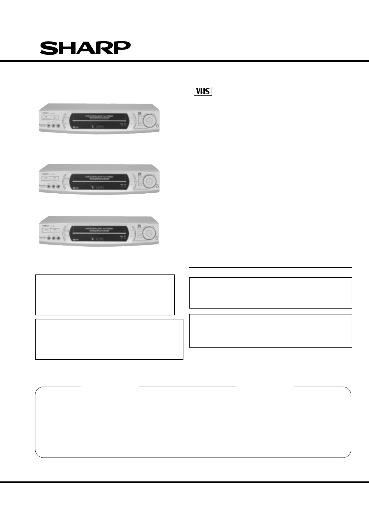
Format: VHS PAL standard
Video recording system: Two rotary heads, helical scan system
Video signal: PAL/SECAM colour and B/G signals,
625 lines
Recording/playing time: 240 min max. with SHARP E-240 tape
(PAL SP)
480 min max. with SHARP E-240 Tape
(PAL LP)ONLY
160 min max. with SHARP T-160 Tape
(NTSC SP Playback) ONLY
320 min max. with SHARP T-160 Tape
(NTSC LP Playback)ONLY
480 min max. with SHARP T-160 Tape
(NTSC EP Playback)ONLY
Tape width: 12.7mm
Tape speed: 23.39 mm/s (PAL SP)
11.70 mm/s (PAL LP)
33.35 mm/s (NTSC SP)
16.67 mm/s (NTSC LP)
11.12 mm/s (NTSC EP)
Antenna: 75 ohm unbalanced
Receiving channel: VHF Channel E2-S41
UHF Channel E21-E69
RF converter output signal: UHF Channel E30-E69
(preset to CH E36)
Power requirement: AC230V, 50Hz
Power consumption: Approx. 20W
1W max. (at Low power mode)
Operating temperature: 5°C to 40°C
Storage temperature: –20°C to 55°C
Weight: Approx. 4 kg
Dimensions: 430 mm (W) x 281 mm (D) x 92 mm (H)
VIDEO
Input: 1.0 Vp-p, 75 ohm
Output: 1.0 Vp-p, 75 ohm
S/N ratio: 45 dB
Horizontal resolution: 250 lines
AUDIO 0 dBs = 0.775 Vrms
Input: Line1; –3.8dBs, 10k ohm
Line2; –3.8dBs, 10k ohm
Line3; –3.8dBs, 47k ohm
(VC-MH761SM)
Output: Line1; –3.8 dBs, 1k ohm
Line2; –3.8dBs, 1k ohm
S/N ratio: 46 dB
Frequency responce: 80 Hz ~ 10 kHz (PAL SP),80 Hz ~ 5 kHz
(PAL LP)
Hi-Fi Dynamic Range: 85dB TYP
Hi-Fi Wow and Flutter: 0.005%
Hi-Fi Frequency Responce: 20 Hz ~ 20 k Hz
Hi-Fi Distortion: 0.5% max.
Hi-Fi Crosstalk: 60 dB min.
Accessories included: 75 ohm coaxial cable
Operation manual
Infrared remote control
Battery (2pcs.)
Note:
The antenna must correspond to the new standard DIN 45325
(IEC 169 - 2) for combined UHF/VHF antenna with 75 ohm connector.
1. TECHNISCHE DATEN
Format: VHS, PAL Norm
Video-Aufzeichnungssystem: Schrägspuraufzeichnung mit zwei
rotierenden Köpfen
Videosignale: PAL/SECAM-Farb-und
B/G-weißsignale, 625 Zeilen
Aufzeichnungs-/: 240 Minuten Max., mit SHARP E-240-
Band (PAL-SP)
NOIR
480 Minuten Max., mit SHARP E-240-Band (PAL-
LP)
NOIR
160 Minuten Max., mit SHARP T-
160-Band (NTSC-SP-Wiedergabe)
NOIR
320MinutenMax., mit SHARPT-160-Band(NTSC-
LP-Wiedergabe)
NOIR
480MinutenMax., mit SHARPT-160-Band(NTSC-
EP-Wiedergabe)
NOIR
Wiedergabezeit Bandbreite: 12,7 mm
Bandgeschwinddigkeit: 23,39 mm/s (PAL-SP)
11,70 mm/s (PAL-LP)
33,35 mm/s (NTSC SP)
16,67 mm/s (NTSC LP)
11,12 mm/s (NTSC EP)
Antenne: 75 Ohm unsymmetrisch
Empfangskanäle: VHF-Kanäle E2-S41
UHF-Kanäle E21-E69
Ausgangssignal HF-Wandler: UHF-Kanäle E30-E69
(voreingestellt auf Kanäl E36)
Stromversorgang: Wechselstrom 230V, 50Hz
Leistungsaufnahme: Ca. 20 W
Ca. 1W
Max. 1W (beim kleinleistungs-Modus)
Betriebstemperatur: 5°bis 40°C
Legerungs temperatur: –20°bis 55°C
Gewicht: Ca. 4kg
Abmessungen:
430 mm (B) x 281 mm (T) x 92mm (H)
VIDEO
Eingang: 1,0 Vs-s, 75 Ohm
Ausgang: 1,0 Vs-s, 75 Ohm
Signal/Geräusch Verhältnis: 45 dB
Horizontale Auflösung: 250 Linie
AUDIO 0 dB = 0,775 Veff
Eingang: Direkteingang 1 : –3,8 dB/10k Ohm
Direkteingang2 : –3.8 dBs/10k Ohm
Direkteingang3 : –3.8 dBs/47k Ohm
Ausgang: Direktausgang 1 : –3,8 dB/1k Ohm
Direktausgang 2 : –3.8 dBs/1k Ohm
Signal/Rausch Abstand: 46 dB
Frequenzwiedergabe: 80 Hz - 10 kHz (PAL SP),80 Hz - 5 kHz
(PAL LP)
Hi-Fi Dynamikbereich: TYP 85dB
Hi-Fi-Tonhöhenschwankungen:
0,005%
Hi-Fi-Frequenzwiedergabe:
20 Hz - 20 k Hz
Hi-Fi-Verzerrung: max. 0,5%
Hi-Fi-Übersprechen: min. 60 dB
Mitgeliefertes Zubehör: 75 Ohm-Koaxialkabel
Bedienungsanleitung
Infrarot-Fernbedienung
Batterie (2 Stücks)
Hinweis:
Die Antenne muß der neuen DIN-Norm 45325 (IEC169-2) für VHF-UHF-
Kombiantennen mit 75 Ohm-Anschluß entsprechen.
As part of our policy of continuous improvement, we reserve the
right to alter design and specifications without notice.
*
Im Sinne der ständigen Verbesserung behalten wir uns das Recht vor, die
äußere Aufmachung und technischen Daten ohne Vorankündigung zu ändern.
4
ROM-TABELLE
MODEL MODELLE VC-FH50GM
blank blank
EP n * * NTSC Luminance level
EP n * * NTSC Chrominance level
SP n * * NTSC Luminance level
SP n * * NTSC Chrominance level
LP p * * PAL Luminance level
LP p * * PAL Chrominance level
blank blank
SP p * * PAL Luminance level
SP p * * PAL Chrominance level
"0" fixed
JP39 A.DUB
JP38 NOT SLOW ATR
JP37 SQ PB
JP36 NTSC PB
JP35 NTSC SKEW
JP34 HEAD2
JP33 HEAD1
JP32 HEAD0
JP31 GAMMA correction
JP30 L/P-5 min
JP29 84 channel
JP28 R/C CODE 1
JP27 DNR
JP26 POST CODE
JP25 SAT CTL
JP24 AV LINK / 16 x 9
JP23 Hi-Fi
JP22 SORT/CLOCK
JP21 DECODER
JP20 SURROUND
JP19 IGR
JP18 NICAM
JP17 G-CODE1
JP16 G-CODE0
JP15 OEM
JP14 LP mode
JP13 F-AV
JP12 2 SCART
JP11 No RF OUT
JP10 TUNER2
JP 9 TUNER1
JP 8 TUNER0
JP 7 SYSTEM1
JP 6 SYSTEM0
JP 5 X 380 FF/REW
JP 4 LOW POWER
JP 3 N/A
JP 2 VPS/PDC
JP 1 COLOUR 1
JP 0 COLOUR 0
DISPLAY IN HEXADECIMAL
NOTATION 12A0
0:LIGHT UP
0:Leuchtet
1:FLASHING
1: Blinkt
VC-FH30GM VC-FH30SM
--
0
7
0
7
3
3
--
4
4
0
0
0
1
1
0
0
1
0
0
0
1
0
0
0
0
1
1
1
1
0
1
0
0
1
0
1
1
1
0
0
0
0
0
0
0
1
0
1
0
1
--
0
7
0
7
3
3
--
4
4
0
1
0
1
1
0
0
1
0
0
0
1
0
0
0
1
1
1
1
1
0
1
0
0
1
0
1
1
1
0
0
0
0
0
0
0
1
0
1
0
1
--
0
7
0
7
3
3
--
4
4
0
0
0
1
1
0
0
1
0
0
0
0
1
1
1
1
0
1
1
0
1
0
1
1
1
0
0
0
0
0
0
0
1
0
0
0
1
0
1
0
1
070733
4400322
1E97015
070733
440322
3E97015
070733
440321
1ED7015
A
B
C
D
E
F
G
H
1234567 8 9 10 11 12
5 6
MAIN CIRCUIT (1) 30SM/GM
A
B
C
D
E
F
G
H
1234567 8 9 10 11 12
7 8
MAIN CIRCUIT (2) 30SM/GM
A
B
C
D
E
F
G
H
1234567 8 9 10 11 12
910
MAIN CIRCUIT (3) 30SM/GM
A
B
C
D
E
F
G
H
1234567 8 9 10 11 12
IMPORTANT SAFETY NOTICE:
BE SURE TO USE GENUINE PARTS FOR SECURING THE
SAFETY AND RELIABILITY OF THE SET.
PARTS MARKED WITH" " AND PARTS SHADED (IN
GREY) ARE ESPECIALLY IMPORTANT FOR MAINTAINING
THE SAFETY AND PROTECTING ABILITY OF THE SET.
BE SURE TO REPLACE THEM WITH PARTS OF SPECIFIED PART
NUMBER
NOTE:
1. The unit of resistance "ohm" is omitted (K: 1000
ohms M: 1 Meg ohm).
2. All resistors are 1/8 watt, unless otherwise noted.
3. The unit capacitance "F" is omitted (
µ=µF, p= µµF).
4. The values in parentheses are the ones in the PB mode:
the values without parentheses are the ones in the REC mode.
VOLTAGE MEASUREMENT CONDITIONS:
1. DC voltages are measured between points indicated and chassis
ground by VTVM, with AC230V/50Hz supplied to unit and all
controls are set to normal viewing picture unless otherwise noted.
2. Voltages are meausred with 10000µVB & W or colour noted.
WAVEFORM MEASUREMENT CONDITIONS:
10000µV 87.5 percent modulated colour bar signal id fed into tuner.
SCHEMATIC DIAGRAM SHALTPLAN
12
11
WICHTIGER SICHEREITSHINWEISE:
IM INTERSSE DER SCHERHEIT UND ZUVERLAS-
SIGKEIT SOLFTEN DIE ORIGINAL TEILE IMMER VERWENDET WERDEN.
DIE MIT " " BEZEICHNETEN BZW. (IM GRAU)
GESCHATTETEN TEILE SIND BESONDERS WICHTING SOWHOL FÜR DIE
SIECHERHEIT ALS AUCH FÜR DIE SICHERE LEISTUNG.
BEIM AUSTAUSCH BITTE IMMER DIE TEILE, WIE VON DEN NUMMERN
VORESCHRIEBEN, VERWENDEN.
SAFETY NOTES:
1. DISCONNECT THE AC PLUG FROM THE AC
OUTLET BEFORE REPLACING PARTS.
2. SEMICONDUCTOR HEAT SINKS SHOULD BE
REGARDED AS POTENTIAL SHOCK HAZARDS
WHEN THE CHASSIS IS OPERATING.
SICHERHEITSHINWEISE:
1. VOR AUSWECHSELN VON TEILEN DEN NETZKABELSTECKER AUS DER
NETZSTECKDOSE ZIEHEN.
2. KÜHLKÖRPER VON HALBLEITERN SOLLTEN BEI BETRIEB DES CHASSIS
ALS MÖGLICHE URSACHEN ELEKTRISCHER SCHALÄGE
BETRACHTET WERDEN.
ANMERKUNGEN:
1. Die Wiederstandseinheit "ohm" wird weggelassen
(K: = 1000 Ohms M: = 1 Megohm).
2. Alle Wiederstände haden 1/8 Watt, sofern nicht anders angegeben.
3. Die Kapazitätseinheit "F" wird weggelassen (
µ= µF, p = µµF).
4. Die in Klammern gesetzten Werte werden in der Wiedergabe-Betriebsart erhalten: die
Werte ohne Klammern werden in der Aufnahme-Betriesart erhalten.
SPANNUNGSMESSBEDINGUNGEN:
1. Gleichspannungen werden zwischen den angegeben Punken und der Chassis mit Hilfe
eines Röhrenvoltmeters gemessen, wobei dem Gerät 230 V Netzstrom (50Hz)
zugeführt wird und alle Bedienungselemente auf ein normales Bild eingestellt sind,
sofern nicht anders angegeben.
2. Spannungen werden mit einem 10000µV Schwarzweißoder Farbsignal gemessen.
WELLENFORMMESSBEDINGUNGEN:
Ein um 87.5% modulierted 1000µV-Farbbalken-signal wird dem Tuner zugeleitet.
CAUTION:
This circuit diagram is original one. Therefore there may be a slight
difference from yours
ANMERKUNG:
Dieses Leitungsschema ist das originale. Daher kann es von ihrem Leiungsschema
etwas verschieden sein.
A
B
C
D
E
F
G
H
1234567 8 9 10 11 12
13 14
MAIN CIRCUIT (4) 30SM/GM
A
B
C
D
E
F
G
H
1234567 8 9 10 11 12
15 16
MAIN CIRCUIT (5) 30SM/GM