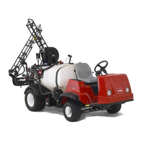
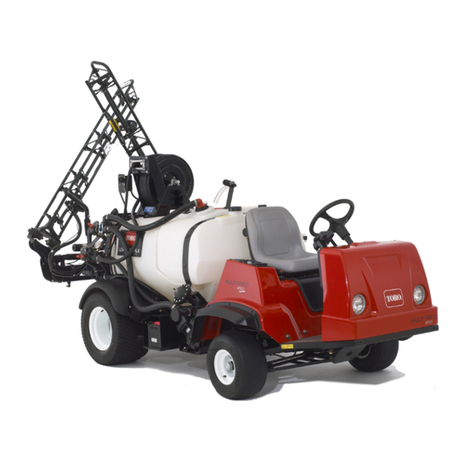
Toro Ultra Sonic Boom 41218 User manual

FormNo.3374-162RevB
UltraSonicBoom™LevelingKit
2010andAfterMulti-Pro®TurfSprayersandWorkman®200Spray
System
ModelNo.41218—SerialNo.312000001andUp
InstallationInstructions
Thisattachmentmaintainsconsistentdistancesfromtheboomnozzlestothegroundwhensprayingover
unevensurfacesandisintendedtobeusedbyprofessional,hiredoperatorsincommercialapplications.Itis
primarilydesignedforsprayinggolfcourseapplications,parks,sportselds,andoncommercialgrounds.It
isdesignedtoonlybeusedinconjunctionwithmachinesdesignatedbythemanufacturer.
ThisproductcomplieswithallrelevantEuropeandirectives.Fordetails,pleaseseetheseparateproduct
specicDeclarationofConformity(DOC)sheet.
Safety
SafetyandInstructionalDecals
Safetydecalsandinstructionsareeasilyvisibletotheoperatorandarelocatednearanyareaof
potentialdanger.Replaceanydecalthatisdamagedorlost.
94-8582
119-9431
©2013—TheToro®Company
8111LyndaleAvenueSouth
Bloomington,MN55420
Registeratwww.Toro.com.OriginalInstructions(EN)
PrintedintheUSA
AllRightsReserved

Installation
LooseParts
Usethechartbelowtoverifythatallpartshavebeenshipped.
ProcedureDescriptionQty.Use
1Nopartsrequired–Preparethemachine.
2Nopartsrequired–Removethehardstops.
Hinge2
Angledstrap(foranuncoveredboom)2
Angledstrap(foracoveredboom)2
Toporbottomstrap2
Compressionspring4
Bushing8
Hex-headbolt(5/16x3-1/4inch)4
Flatwasher12
3
Locknut(5/16inch)4
Assemblethesensormounting
hardware.
Sonicboomsensor2
Bracket2
Programmingplug2
Sensorcover2
Lowersensorhousing2
Captube2
Sensorguardbracket2
Sensorcable(4m)2
Largenut4
U-bolt6
Locknut(1/4inch)8
Bolt(5/16x3/4inch)8
Bolt(5/16x1-1/4inch)4
Locknut(5/16inch)12
4
Cabletie12
Installthesonicboomsensors.
Mountplate1
Relay4
Bolt(1/4x5/8inch)4
Lockwasher(1/4inch)4
Nut(1/4inch)4
Wireharness1
Screw(#10)4
Nut(#10)4
ElectronicControlUnit(ECU)1
Fuseretainer1
Bolt(1/4x1-1/4inch)4
Locknut(1/4inch)4
Bolt(5/16x3/4inch)2
Lockwasher(5/16inch)2
Flatwashers2
U-boltclamps2
5
Nut(5/16inch)4
Mounttheelectroniccontrols.
2

ProcedureDescriptionQty.Use
Decal,94-85821
6Lightassembly1Installtheindicatorlight.
Rockerswitch1
Cableties6
Indicatorlight(Workman200only)1
7Grommet(Workman200only)1
Installthecontrols.
8Nopartsrequired–Calibratethesonicbooms.
Note:Decal119-9431isusedwithahand-helddiagnostictoolandthereforeisnotinstalledonthemachine.
Note:Determinetheleftandrightsidesofthemachinefromthenormaloperatingposition.
1
PreparingtheMachine
NoPartsRequired
Procedure
Positionthemachineonalevelsurface,stoptheengine,
removetheignitionkey,andengagetheparkingbrake.
CAUTION
Ifyouleavethekeyintheignitionswitch,someone
couldaccidentlystarttheengineandseriously
injureyouorotherbystanders.
Removethekeyfromtheignitionswitchbefore
installthekit.
2
RemovingtheHardstops
NoPartsRequired
Procedure
Ifyourmachinehashardstopsinstalled,theymustbe
removedbeforeinstallingtheSonicBoomKit.The
hardstopsarelocatedinthecenterboomofthecaged
boomsandcanbeseenwhentheboomsareinthe
upright,transportposition.Ifyourmachinedoesnot
havehardstopsinstalled,skiptothenextprocedure.
1.Raisetheboomsintothetransportpositionand
removetheignitionkey.
2.Removethe4bolts(5/16x1inch)andnuts(5/16
inch)thatsecurethestopstothecenterboomframe
asshownin(Figure1).
Note:Removethehardstopassembliesonboth
sidesofthecenterboom.Retainallpartsforlater
use.
G009415
1
2
3
4
Figure1
Rightsideshown
1.Centerboomassembly3.Bolt(5/16x1inch)
2.Assembledbracketand
bumper
4.Nut(5/16inch)
3

3
AssemblingtheSensor
MountingHardware
Partsneededforthisprocedure:
2Hinge
2Angledstrap(foranuncoveredboom)
2Angledstrap(foracoveredboom)
2Toporbottomstrap
4Compressionspring
8Bushing
4Hex-headbolt(5/16x3-1/4inch)
12Flatwasher
4Locknut(5/16inch)
Procedure
Note:Howyouassemblethesensormounting
hardwaredependsuponwhethertheCoveredBoomKit
(model41602)isinstalled.
1.Layoutthehingesandstrapsasshownin
Figure2(foranuncoveredboom)orFigure3(fora
coveredboom).
Note:Thereare2setsof2angledstrapsinloose
parts.Onesetisforanuncoveredboomandthe
othersetisforacoveredboom.Youwillhaveone
setof2angledstraps(eitherforthecoveredboom
orfortheuncoveredboom)thatyouwillnotuse
onthemachine.
Note:Thetopstrapsfortheuncoveredboomsalso
serveasthebottomstrapsforthecoveredbooms.
1
3
2
G017128
3
4
Figure2
Foruncoveredboomsonly
1.Hinge(2)3.Bushings(8)
2.Angledstrap(2)4.Topstrap
1
3
2
G017129
3
4
Figure3
Forcoveredboomsonly
1.Hinge(2)3.Bushing(8)
2.Angledstrap(2)4.Bottomstrap
2.Insertthebushingsintotheweldedtubeopenings
inthehingesandstrapsasshowninFigure2or
Figure3.
3.Installaatwasheroneachofthe2hex-headbolts
(3-1/4inch).
4

4.Inserttheboltsthroughthehingedweldedtube
openings,hinges,andstraps(Figure4).
Figure4
Hardwareforacoveredboomshown
1.Hex-headbolt4.Springs
2.Flatwasher5.Locknuts(5/16inch)
3.Weldedtubeopening
5.Installaatwasherontheexposedendofeachof
thebolts.
6.Installaspringontheendofeachbolt(Figure4).
7.Installaatwasherandalocknutontheendofeach
bolt,andtightenthelocknutsuntilthereisnoslack
inthespring.
Note:Checktoensurethatthehingesarenotso
tightthatthemountedsensorsdonotfreelypivot
onthehinges.
4
InstallingtheSonicBoom
Sensors
Partsneededforthisprocedure:
2Sonicboomsensor
2Bracket
2Programmingplug
2Sensorcover
2Lowersensorhousing
2Captube
2Sensorguardbracket
2Sensorcable(4m)
4Largenut
6U-bolt
8Locknut(1/4inch)
8Bolt(5/16x3/4inch)
4Bolt(5/16x1-1/4inch)
12Locknut(5/16inch)
12Cabletie
Procedure
1.Installamountingbracketonthefrontsideofeach
boomneartheoutermostnozzlewith3U-boltsand
6locknuts(1/4inch)(Figure5andFigure6).
1
2G017147
Figure5
Frontview
1.Mountingbracket(2)2.U-bolt(6)
5

1
2
G017148
Figure6
Rearview
1.Mountingbracket(2)2.Locknuts(1/4inch)(12)
2.Installthesensorguardbracketontothemounting
bracketwith2bolts(5/16x3/4inch)and2ange
nuts(5/16inch)asshowninFigure7.
1
G017149
Figure7
1.Sensorguardbracket
3.Installthesensormountinghardwareontothesensor
guardbracketwith2bolts(5/16x3/4inch)and
2locknuts(5/16inch)asshowninFigure8(fora
coveredboom)orFigure9(foranuncoveredboom).
G017150
12
Figure8
Foracoveredboomonly
1.Sensorguardbracket2.Hinge(ofsensormounting
hardware)
G017157
1
2
Figure9
Foranuncoveredboomonly
1.Sensorguardbracket2.Hinge(ofsensormounting
hardware)
4.Installthelowersensorhousingontothesensor
mountinghardwarewith2bolts(5/16x1-1/4inch)
and2locknuts(5/16inch)(Figure10).
6

1
2
4
3
3
5
G017151
6
7
8
Figure10
Uncoveredboomcongurationshown
1.Cover5.Captube
2.Sensor6.Bolts(5/16x1-1/4inch)
3.Largenut7.Locknuts(5/16inch)
4.Lowersensorhousing8.Finishedsensorassembly
5.Installtheprogrammingplugonthesensor
(Figure11).
Important:Ensurethatyoualignthearrow
belowthesideways“T”withthenotchonthe
topedgeofthesensor(Figure11).
Figure11
1.Sideways“T”3.Notch
2.Arrowsaligned4.Sensor
6.Insertthesensorintothelowersensorhousing,and
secureitwith2largenutsprovidedwiththesensor
(Figure10).
Note:Discardthelockwashersthatcomewiththe
sensors.
7.Installthecaptubeandthecover(Figure10).
Note:Ensurethatthesensorwireisroutedthrough
thesmallopeninginthecoverbeforeinstallingthe
sensorcover.
8.Securethewirecomingfromthesensortotheboom
withcableties.
Important:Ensurethatyouallowenoughslack
inthewirearoundthesensorsothatthesensor
canfreelypivotonthehingewithoutpullingon
thewire.
9.Repeatthestepsabovefortheotherboom.
Note:Forcoveredboomsonly:Thesensorsshould
notdetecttheboomcoverasthismayinterferewith
thesignal.Ifyouexperienceanydifcultiesduringthe
calibrationprocess,checkthesensorstoensurethat
theirsignalsdonotdetecttheboomcover.
7

5
MountingtheElectronic
Control
Partsneededforthisprocedure:
1Mountplate
4Relay
4Bolt(1/4x5/8inch)
4Lockwasher(1/4inch)
4Nut(1/4inch)
1Wireharness
4Screw(#10)
4Nut(#10)
1ElectronicControlUnit(ECU)
1Fuseretainer
4Bolt(1/4x1-1/4inch)
4Locknut(1/4inch)
2Bolt(5/16x3/4inch)
2Lockwasher(5/16inch)
2Flatwashers
2U-boltclamps
4Nut(5/16inch)
Procedure
1.Secure4relaystothefrontofthemountplatewith
4bolts(1/4x5/8inch),4lockwashers(1/4inch),
and4nuts(1/4inch)asshowninFigure12.
1
23
4
5
6
9
8
7
G018924
Figure12
1.Relay6.Nut(#10)
2.Nut(1/4inch)7.Screw(#10)
3.Lockwasher(1/4inch)8.Fuseblock
4.Bolt(1/4x5/8inch)9.Fuseretainer
5.Mountplate
2.Securethefuseblockendsofthewiringharnessand
thefuseretainertothemountingplatewith4screws
(#10)and4nuts(#10)asshowninFigure12.
3.SecuretheECUtothemountingplatewith4bolts
(1/4x1-1/4inch)and4locknuts(1/4inch)as
showninFigure13.
G016081
12
34
Figure13
1.Bolt(1/4x1-1/4inch)3.Mountplate
2.ECU4.Locknut(1/4inch)
4.Connecttherelayleadsonthewiringharnesstothe
4relaysonthemountingplate.
8

5.Connectthecontrollerleadonthewiringharness
totheECU.
6.Installthemountplatetothevehicleframe,under
thedashboard.
A.FortheMulti-Pro1200and1250:Installthe
mountplateusing2bolts(5/16x3/4inch),2
lockwashers(5/16inch),and2atwashersas
showninFigure14.
G016082
1
2
345
Figure14
Frameunderthedashboard
1.Bolt(5/16x3/4inch)4.ECMandMountplate
2.Lockwasher(5/16inch)5.Vehicleframe
3.Flatwasher
B.FortheWorkman200SpraySystem:Install
themountplateusing2U-boltclampsand2nuts
(5/16inch)asshowninFigure15.
G016282
1
2
3
4
Figure15
1.Vehicleframe3.Mountplate
2.U-boltassembly4.Nut(5/16inch)
6
InstallingtheIndicatorLight
Partsneededforthisprocedure:
1Decal,94-8582
1Lightassembly
Procedure
1.Installdecal94-8582overthelightholeinthedash
(Figure16).
G016376
1
2
3
Figure16
1.Decal94-85823.Pushnut
2.Light
2.Installthelightinthedashandsecureitfrom
underneaththedashwiththepushnut(Figure16).
3.Connectthelighttothecorrespondingconnectoron
thebranchofthewiringharness.
7
InstallingtheControls
Partsneededforthisprocedure:
1Rockerswitch
6Cableties
1Indicatorlight(Workman200only)
1Grommet(Workman200only)
InstallingtheControlsonaMultiPro
1200or1250TurfSprayer
InstallingtheSwitches
9

1.Removethespraycontrolpaneltoexposethe
bottomside(Figure17forthe1200andFigure18for
the1250).
Figure17
MultiPro1200
1.Sonicboomswitch
location
2.Spraycontrolpanel
Figure18
MultiPro1250
1.Plug3.Notch(atback)
2.Switch4.Spraycontrolpanel
2.Removethepluginthesonicboomslotfromthe
spraycontrolpanelonthevehicle,andinstallthe
rockerswitchprovidedinitsplace(Figure17forthe
1200andFigure18forthe1250).
Note:Ensurethattheorientationoftheswitch
matcheswhatisshowninFigure18,withthenotch
pointingtowardtherearofthevehicle.
WiringtheSwitches
1.Routethebranchofthesonicboomwireharness
withthe3largeconnectorsintothecontrolpanel
area.
2.Ifboomliftswitchesareinstalled,removeany
existingconnectorspluggedintotheliftswitches.
3.Connecttheconnectorslabeled“leftboomlift
switch”and“rightboomliftswitch”tothe
correspondingpanelswitches.
4.Connecttheconnectorlabeled“sonicboomswitch”
tothesonicboomswitch.
5.Routethefreeendofthewiringharnessdown
throughtheoorandrearward,followingthespray
systemwireharnesstothecenterboomassemblyat
thebackofthevehicle.
Note:Usecabletiestosecurethewiringharness
totheotherwiringharnessesawayfromtheengine
andmovingparts.
6.Installthespraycontrolpanelandsecureitwiththe
fastenersthatyouremovedpreviously.
ConnectingtheWiringtotheFuseBlock
1.Routethebranchofthesonicboomwiringharness
withthesmallspadeconnectorandaringorfork
terminalintotheseatboxandtothefusearea.
2.Lifttheseattoaccessthefusearea,andlocatethe
auxiliarysolenoidandgroundterminalblock.
3.Connecttheringlabeledgroundontheblackwireto
thegroundterminalblock(Figure19).
Figure19
1.Blackwire3.Redwire
2.Groundterminalblock4.Auxiliarysolenoid
4.Connecttheredwiretotheloadsideoftheauxiliary
solenoid.
10

Note:Theloadsidecanbedeterminedbytesting
bothsolenoidpostswhentheignitionisturnedoff.
Thehotsidewillreadapproximately12V ,whilethe
loadsidewillhavenovoltage.Theloadsidecanbe
conrmedbyturningtheignitiontotheRunorOn
positionandtestingtheloadsideagain.Theload
sidewillreadapproximately12Vwiththeignition
on.TurntheignitiontoOffandremovethekey
beforecontinuingwithanyoftheinstallationor
maintenance.
5.Lowertheseat.
InstallingtheControlsonaWorkman
SpraySystem
InstalltheSwitches
1.Removethefastenersthatsecurethefrontcover
tothecontrolpanelhousingtoaccesstheinternal
components.
Note:Retainallfasteners.
2.Drilla0.50-inchdiameterholetoaccommodatethe
indicatorlightincontrolpanelcover(Figure20).
G016286
11
2
3
Figure20
1.Screw3.Drilledhole(0.50inch
diameter)
2.Latches
3.Installtheindicatorlightthroughthebackofthe
hole,andsecureittothefrontpanelwiththe
fastenersthatareincluded(Figure21).
4.Removethesonicboomswitchplugfromthefront
panel,andinstallthesonicboomrockerswitch
(Figure21).
Figure21
1.Spraycontrolpanel5.Indicatorlight,install
2.Sonicboomplug6.Sonicboomswitch
3.Existingboomliftswitches7.Sonicboomconnector,
fromsonicboomwire
harness
4.Existingboomlift
connectors
8.Boomliftconnectors,from
sonicboomwireharness
5.Locateanddisconnecttheplugsfortheboomlift
switches(Figure21).
Important:Donotcutorremoveanyunused
connectors.Storetheunusedconnectorsinthe
controlboxforfutureuseintheeventthatthe
sonicboomkitisremoved.
6.Changetheorientationoftheboomliftswitches:
A.Locatetheboomliftswitchesinthecontrol
panel,andremovebothswitchesfromthepanel.
B.Usingaatheadscrewdriverorsimilartool,
gentlyprytherockerswitchcoversfromthe
switchbodies(Figure22).
11

Figure22
1.Switch,withnotchinthe
rear
3.Switchbody,rotated180°
2.Removethecover4.Installcover,notchinthe
front
C.Holdingtheswitchcoverinposition,ipthe
switchbody180degreessothattheconnector
notchisfrontleftcorner(Figure22).
D.Presstherockerswitchcoversontotheswitch
bodiesinthisneworientationuntilthecover
snapsintoplace(Figure22).
E.Installtheswitchestotheiroriginalpositionin
thecontrolpanel.
Note:Ensurethattheorientationofthenotch
oftheswitchpointstowardthetopleftofthe
controlbox.
WiringtheSwitchesandIndicatorLight
1.Cutandremovetheexistinggrommetinthebaseof
thecontrolpanel.Discardthegrommet.
Important:Takeprecautionsnottocutthe
existingwiresandharnesswhencuttingoutthe
existinggrommet.
2.Routethefreeendofthewiringharnessupthrough
theopeninginthecontrolpanel,keepingthebranch
withtheringterminaloutsidethecontrolpanel.
3.Splitthenewgrommetincludedinthekitandwrap
thearoundthewiringharnessatthebaseofthe
controlpanel.
4.Installthegrommetstothebaseofcontrolpanelin
placeofthegrommetthatyouremovedpreviously.
5.Connecttheconnectorslabeled“leftboomlift
switch”and“rightboomliftswitch”tothe
correspondingpanelswitches.
6.Connecttheconnectorlabeled“sonicboomswitch”
tothesonicboomswitch.
7.Connectthelightindicatortothewiringharness
withtwospadeconnectors.
8.Installthefrontcontrolpanelcovertothecontrol
boxusingthefastenersthatyouremovedpreviously
(Figure20).
9.Routetheremainderoftheharnessrearward,along
theexistingsprayerharnesstorearofthemachine.
10.Securetheharnesseswithcableties.
ConnectingtheWiringtotheFuseBlock
1.Locatethebranchofthewiringharness,withthe
ringterminalforgroundandsmallpowerterminal,
androuteitunderthedashtothefuseblockarea.
2.Connecttheringontheblackwiretotheground
bolt(Figure23).
Figure23
1.Fuseblock4.Blackwire
2.Redwire,fromharness5.Groundbolt
3.Correspondingwire,from
fuseblock
3.Removetheshortextensionwirefromtheredwire
andconnecttheblackconnectortothemating
connectorinthefuseblock.
4.Locatethelongbranchextendingfrommiddleof
thewiringharnesswiththepositiveringterminal.
5.Routethelongbranchalongexistingwiringtothe
batteryarea.
6.Removethebatterycoverifnecessaryandconnect
theringterminaltothepositivebatterypostclamp
usingexistingfasteners.
12

Note:Replacethecoverifnecessary.
Note:Tiebackanyloosewiringtoprotectitfrom
beingdamaged.
8
CalibratingtheSonicBooms
NoPartsRequired
Procedure
Inthisprocedure,youwillhave20secondstocalibrate
thesensorsonthebooms.Thedistanceyousetbetween
thesensoroneachboomandthegroundafterthe
20-secondcalibrationperiodistheboomheightsetting
inautomaticmodeuntilthenexttimeyoucalibratethe
sensor.Afterthe20seconds,aself-calibratingprocess
occursforupto2minutes,duringwhichthecontroller
establishesthisdistanceandthen“learns”theow
characteristicsofthehydraulicliftcylindervalves.
Note:Foruncoveredbooms:Thedefaultheight
settingis20inches(51cm)fromthenozzletothe
ground.If,aftersettingaboomtoaheightdifferent
fromthatofthefactorydefaultsetting,youwishto
restorethecalibrationtothefactory-defaultsetting,
calibratetheboomwiththeboominthecradle.For
coveredbooms:Thedefaultheightsettingof20inches
(51cm)isforuncoveredboomsonly.Youmustcalibrate
thesensorsoncoveredbooms.
1.Ensurethattheturfsprayerisparkedandaway
fromanytrees,buildings,vehicles,debris,and
undergroundutilitiesandplumbing.
2.Lowertheboomstothehorizontalposition;referto
theOperator'sManualforinformationonAdjusting
theActuatorstolevelthebooms.
3.Turnofftheignitionkey.
4.Pressthesonicboomswitchonthedashboardtothe
Autoposition(Figure24).
Figure24
1.Sonicboomswitch
5.WhilepressingandholdingboththeLeftLower
switchandtheRightRaiseswitch,turntheignition
keyandstartthemachine.
6.Releasetheboomswitches.
Note:Thegreenlightonthesonicboomswitchwill
ashrapidly,indicatingthatthesonicboomsystem
isincalibrationmode.Younowhave20seconds
tousetheraiseandlowerboomswitchestosetthe
desireddistancefromtheboomstotheground.
Afterthe20seconds,thegreenlightwillashslowly.
7.UsetheRaiseandLowerswitchestoadjustthe
heightofeachboomuntilyouachievethedesired
distancefromthesensorontheboomtotheground.
8.Allowtheself-calibratingprocesstocomplete;wait
fortheslowlyashinggreenlightonthesonicboom
switchtostop.
Note:Theself-calibratingprocessmaytakeupto
2minutestocomplete.Donotinterruptthesensor
signalduringtheself-calibrationprocess,suchas
movingyourfootunderasensor.
13

Operation
UsingtheControls
TheSonicboomswitchislocatedonthedashboard
andhas2settings:AutomaticandManual.
•Automaticmode:Thismodeenablesthe
automaticmovementofthebooms,enablingthe
boomtipstocontinuallyremainthedesireddistance
fromtheground.Toactivatetheautomaticmode,
pressthesonicboomAutomodeswitchandtapon
thelowerboomswitch(es)tomovetheboomtothe
desireddistancefromtheground.
Note:Youcantemporarilyoverridetheautomatic
operationoftheboomsusingtheboomswitches
toraiseorloweroneorbothbooms.Tolowerthe
boommanuallywhilethesystemisinautomatic
mode,holdthelowerboomswitchuntilyoureach
thedesiredboomheight.Toraisetheboom
manuallywhilethesystemisinautomaticmode,
simplyholdtheraiseboomswitchuntilyoureach
thedesiredboomheight.Ifyouadjustonlyone
boom,theotherboomcontinuestofunction
automatically.Toresumetheautomaticmode,tap
thelowerboomswitchtomovetheboomtothe
desireddistancefromtheground.
•Manualmode:Thismodeturnsofftheautomatic
adjustmentofthebooms,andallowsyoutocontrol
theboomsmanually.
TheSonicboomlightisonthesonicboomswitch
displaysthestatusofthesonicboomsystemasfollows:
•Oncontinuously:Thesonicboomsystemison
andoperatingnormally.
•Flashingquickly:Thesystemisincalibration
mode,whichlastsfor20seconds.
•Flashingslowly:Thereisanerrorinthesystem
oryouhaveoverriddentheautomaticmodeby
operatingoneorbothoftheboomsmanuallywhile
thesystemisinautomaticmode.
Note:Intheeventthatthereisafaultinthesonic
boomsystem(e.g.,thereisnosignalcomingfroma
sensor),theboomwillraiseforafewsecondsand
thenstop,andthelightontheboomswitch(located
onthedashboard)willashslowly,indicatingthat
oneoftheboomshasstopped.Also,theindicator
lightonthearmrestwillash,indicatingafault.
Theindicatorlightisthesmallredlightlocatedon
thearmconsoleanddisplaysthestatusofthesonic
boomsystemasfollows:
•Onmomentarily:Thelightcomesonwhenyou
activatethesonicboomsystem.Thelightwillturn
offafterafewsecondsandremainoffaslongas
thesystemisoperatingproperly.
•Flashing:Thereisanactivefaultinthesonic
boomsystem.
14

Maintenance
Cleaning
Cleanthesensorsperiodicallywithadampcloth.Ifa
sensorisdamagedorexcessivelydirty,replaceit.
Important:Donotspraywateratoronthesensors.
Watersprayedunderevenhouseholdpressure
candamagethesensor.Alwayscoverthesensors
completelybeforewashingthesprayer.
Note:Whentheboomsareinthecradleforextended
periodsoftime,thesealaroundeachsensor(whichis
orientedupward)maygetexposedtoultravioletlightand
graduallydeteriorate.Keepthebottomofthesensors
frombeingexposedtodirectsunlightwheneverpossible.
Storage
Wheneveryouarenotusingthesensorsforanextended
periodoftime,putthesafetycapsonthesensorsto
protectthemfromtheoutdoorelements.
15

Troubleshooting
Note:Refertotheservicemanualforadditionaldiagnosticinformation.Productelectricalschematicsmaybe
foundatwww.Toro.com.
ProblemPossibleCauseCorrectiveAction
1.Afuseisblown.1.Replacethefuse.
2.Thelightisburnedout.2.Replacethelight.
Oneorbothboomsmalfunction;thesonic
boomlightisOff.
3.Theelectroniccontrollerorwiringis
damaged.
3.ContactanAuthorizedToroDistributor.
1.Thereisaminorsystemerror.1.Lowertheaffectedboom(s)usingthe
boomswitch(es)tocleartheerror.
2.Thereisasystemerrorthatrepeats
afterclearingtheerror.
2.Iftheerrorrepeats,contactan
AuthorizedToroDistributor.
Oneorbothboomsmalfunction;thesonic
boomlightashesslowly.
3.Thereisahydraulicormechanical
failure.
3.Repairthehydraulicormechnical
problem.
Oneorbothboomsaremalfunctioning;
thesonicboomlightison.
1.Thesensorcoversareblockingor
swingingintothesensorpath
1.Installcovertothetopsideofthe
sensor.
16

Notes:
17

Notes:
18

Notes:
19

TheToroTotalCoverageGuarantee
ALimitedWarranty
ConditionsandProductsCovered
TheT oroCompanyanditsafliate,ToroWarrantyCompany,pursuant
toanagreementbetweenthem,jointlywarrantyourT oroCommercial
product(“Product”)tobefreefromdefectsinmaterialsorworkmanship
fortwoyearsor1500operationalhours*,whicheveroccursrst.This
warrantyisapplicabletoallproductswiththeexceptionofAerators
(refertoseparatewarrantystatementsfortheseproducts).Wherea
warrantableconditionexists,wewillrepairtheProductatnocosttoyou
includingdiagnostics,labor,parts,andtransportation.Thiswarranty
beginsonthedatetheProductisdeliveredtotheoriginalretailpurchaser.
*Productequippedwithanhourmeter.
InstructionsforObtainingWarrantyService
YouareresponsiblefornotifyingtheCommercialProductsDistributoror
AuthorizedCommercialProductsDealerfromwhomyoupurchasedthe
Productassoonasyoubelieveawarrantableconditionexists.Ifyouneed
helplocatingaCommercialProductsDistributororAuthorizedDealer,or
ifyouhavequestionsregardingyourwarrantyrightsorresponsibilities,
youmaycontactusat:
ToroCommercialProductsServiceDepartment
ToroWarrantyCompany
8111LyndaleAvenueSouth
Bloomington,MN55420-1196
952–888–8801or800–952–2740
E-mail:[email protected]
OwnerResponsibilities
AstheProductowner,youareresponsibleforrequiredmaintenance
andadjustmentsstatedinyourOperator'sManual.Failuretoperform
requiredmaintenanceandadjustmentscanbegroundsfordisallowinga
warrantyclaim.
ItemsandConditionsNotCovered
Notallproductfailuresormalfunctionsthatoccurduringthewarranty
periodaredefectsinmaterialsorworkmanship.Thiswarrantydoesnot
coverthefollowing:
•Productfailureswhichresultfromtheuseofnon-T ororeplacement
parts,orfrominstallationanduseofadd-on,ormodiednon-T oro
brandedaccessoriesandproducts.Aseparatewarrantymaybe
providedbythemanufactureroftheseitems.
•Productfailureswhichresultfromfailuretoperformrecommended
maintenanceand/oradjustments.Failuretoproperlymaintainyour
ToroproductpertheRecommendedMaintenancelistedinthe
Operator’sManualcanresultinclaimsforwarrantybeingdenied.
•ProductfailureswhichresultfromoperatingtheProductinan
abusive,negligent,orrecklessmanner.
•Partssubjecttoconsumptionthroughuseunlessfoundtobe
defective.Examplesofpartswhichareconsumed,orusedup,
duringnormalProductoperationinclude,butarenotlimitedto,brake
padsandlinings,clutchlinings,blades,reels,rollersandbearings
(sealedorgreasable),bedknives,sparkplugs,castorwheelsand
bearings,tires,lters,belts,andcertainsprayercomponentssuchas
diaphragms,nozzles,andcheckvalves,etc.
•Failurescausedbyoutsideinuence.Conditionsconsideredtobe
outsideinuenceinclude,butarenotlimitedto,weather,storage
practices,contamination,useofunapprovedfuels,coolants,
lubricants,additives,fertilizers,water,orchemicals,etc.
•Failureorperformanceissuesduetotheuseoffuels(e.g.gasoline,
diesel,orbiodiesel)thatdonotconformtotheirrespectiveindustry
standards.
•Normalnoise,vibration,wearandtear,anddeterioration.
•Normal“wearandtear”includes,butisnotlimitedto,damageto
seatsduetowearorabrasion,wornpaintedsurfaces,scratched
decalsorwindows,etc.
Parts
Partsscheduledforreplacementasrequiredmaintenancearewarranted
fortheperiodoftimeuptothescheduledreplacementtimeforthatpart.
Partsreplacedunderthiswarrantyarecoveredforthedurationofthe
originalproductwarrantyandbecomethepropertyofToro.T orowill
makethenaldecisionwhethertorepairanyexistingpartorassemblyor
replaceit.Toromayuseremanufacturedpartsforwarrantyrepairs.
DeepCycleandLithium-IonBatteryWarranty:
DeepcycleandLithium-Ionbatterieshaveaspeciedtotalnumberof
kilowatt-hourstheycandeliverduringtheirlifetime.Operating,recharging,
andmaintenancetechniquescanextendorreducetotalbatterylife.Asthe
batteriesinthisproductareconsumed,theamountofusefulworkbetween
chargingintervalswillslowlydecreaseuntilthebatteryiscompletelyworn
out.Replacementofwornoutbatteries,duetonormalconsumption,
istheresponsibilityoftheproductowner.Batteryreplacementmaybe
requiredduringthenormalproductwarrantyperiodatowner’sexpense.
Note:(Lithium-Ionbatteryonly):ALithium-Ionbatteryhasapartonly
proratedwarrantybeginningyear3throughyear5basedonthetime
inserviceandkilowatthoursused.RefertotheOperator'sManualfor
additionalinformation.
MaintenanceisatOwner’sExpense
Enginetune-up,lubrication,cleaningandpolishing,replacementoflters,
coolant,andcompletingrecommendedmaintenancearesomeofthe
normalservicesToroproductsrequirethatareattheowner’sexpense.
GeneralConditions
RepairbyanAuthorizedT oroDistributororDealerisyoursoleremedy
underthiswarranty.
NeitherTheToroCompanynorToroWarrantyCompanyisliablefor
indirect,incidentalorconsequentialdamagesinconnectionwiththe
useoftheToroProductscoveredbythiswarranty,includingany
costorexpenseofprovidingsubstituteequipmentorserviceduring
reasonableperiodsofmalfunctionornon-usependingcompletion
ofrepairsunderthiswarranty.ExceptfortheEmissionswarranty
referencedbelow,ifapplicable,thereisnootherexpresswarranty.
Allimpliedwarrantiesofmerchantabilityandtnessforuseare
limitedtothedurationofthisexpresswarranty.
Somestatesdonotallowexclusionsofincidentalorconsequential
damages,orlimitationsonhowlonganimpliedwarrantylasts,sothe
aboveexclusionsandlimitationsmaynotapplytoyou.Thiswarranty
givesyouspeciclegalrights,andyoumayalsohaveotherrightswhich
varyfromstatetostate.
Noteregardingenginewarranty:
TheEmissionsControlSystemonyourProductmaybecoveredby
aseparatewarrantymeetingrequirementsestablishedbytheU.S.
EnvironmentalProtectionAgency(EPA)and/ortheCaliforniaAir
ResourcesBoard(CARB).Thehourlimitationssetforthabovedonot
applytotheEmissionsControlSystemWarranty.RefertotheEngine
EmissionControlWarrantyStatementsuppliedwithyourproductor
containedintheenginemanufacturer’sdocumentationfordetails
CountriesOtherthantheUnitedStatesorCanada
CustomerswhohavepurchasedT oroproductsexportedfromtheUnitedStatesorCanadashouldcontacttheirT oroDistributor(Dealer)toobtain
guaranteepoliciesforyourcountry,province,orstate.IfforanyreasonyouaredissatisedwithyourDistributor'sserviceorhavedifcultyobtaining
guaranteeinformation,contacttheT oroimporter.374-0253RevB
Table of contents
Other Toro Paint Sprayer manuals

Toro
Toro 131-3301 Service manual

Toro
Toro 41107 User manual

Toro
Toro Spray Master User manual

Toro
Toro Spray Master Series User manual

Toro
Toro 41440 Specifications

Toro
Toro 41165 User manual

Toro
Toro 41177 Multi-Pro 1250 User manual

Toro
Toro GeoLink 41624 User manual

Toro
Toro 41564 User manual

Toro
Toro MultiPro 1750 User manual

Toro
Toro Multi-Pro 5800 User manual

Toro
Toro 41581 User manual

Toro
Toro Multi-Pro 5800 User manual

Toro
Toro Multi Pro 1200 User manual

Toro
Toro 41605 User manual

Toro
Toro 41178 Multi-Pro 1200 User manual

Toro
Toro SprayMaster 34246 User manual

Toro
Toro 34215 User manual

Toro
Toro Multi Pro WM 41240 User manual

Toro
Toro 125-8120 User manual