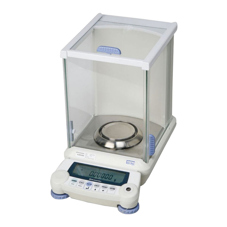
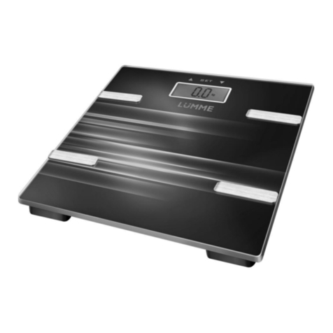
Shimadzu ATX224 User manual

Document No. 321-78009A
ElectronicAnalytical Balance
ATX /ATY Series
Service Manual

1
Table of Contents
1. OperationsforAdjustment.............................................................................................................................................1
1.1. Entering the Service Mode.....................................................................................................................................1
1.2. Contents of Service Menu......................................................................................................................................2
1.3. Service ModeFunctions........................................................................................................................................3
2.
DisassemblingandAssembling the Balance.............................................................................................................5
2.1. Precautions...............................................................................................................................................................5
2.2. Inspecting the Balance Interior (Removing the Caseand PanSupporter)...................................................6
2.3. Replacing Components..........................................................................................................................................8
2.3.1. ReplacingtheFrontGlassASSY(C8).................................................................................................................................8
2.3.2. ReplacingtheSideGlassASSY(C6,C7)...........................................................................................................................9
2.3.3. ReplacingtheRoofGlassASSY(C5).................................................................................................................................9
2.3.4. ReplacingtheDisplayBoardASSY(B2).............................................................................................................................9
2.3.5. ReplacingthePowerBoardASSY(B4)........................................................................................................................... 10
2.3.6. ReplacingtheAnalogBoardASSY(B3)........................................................................................................................... 10
2.3.7. ReplacingtheWeightLoaderASSY(27)..........................................................................................................................11
2.3.8. ReplacingtheUnitASSY(1)............................................................................................................................................. 12
2.3.9. ReplacingtheDetectorASSY(U11).................................................................................................................................13
2.3.10. ReplacingtheForceCoilASSY(L1).................................................................................................................................13
2.3.11. ReplacingtheStopperPlate(U14)................................................................................................................................... 16
2.3.12. ReplacingtheStopperLever(U15)................................................................................................................................... 16
3.
Checking the Electronic Board................................................................................................................................... 17
3.1. DisplayBoardASSY (B2).................................................................................................................................... 17
3.2. Analog Board ASSY (B3)..................................................................................................................................... 17
3.3. Preamp BoardASSY (B1)................................................................................................................................... 18
3.4. PowerBoardASSY (B4)...................................................................................................................................... 18
4.
HardwareAdjustment................................................................................................................................................... 19
4.1. Adjusting the DetectorASSY(U11)Height...................................................................................................... 19
4.2. Adjusting the Tilt Error........................................................................................................................................ 20
4.3. Adjusting the Balance......................................................................................................................................... 21
4.4. Adjusting the Cornerload Error ......................................................................................................................... 22
5.
SoftwareAdjustment.................................................................................................................................................... 23
5.1. EEPROM Initialization.......................................................................................................................................... 23
5.2. Model Selection.................................................................................................................................................... 23
5.3. Releasing and Setting the Setting Information Lock..................................................................................... 25
5.3.1. ReleasingtheSettingInformationLock............................................................................................................................ 25
5.3.2. SettingtheSettingInformationLock.................................................................................................................................25
5.4. Inputting Weight Valuesfor LinearityAdjustment.......................................................................................... 25

ii
5.5. LinearityAdjustment............................................................................................................................................ 26
5.6. Internal Weight Calibration (PCAL)(ATX Only)............................................................................................... 27
5.6.1. OperationProcedureandProcess................................................................................................................................... 27
5.7. Sensitivity Calibration.......................................................................................................................................... 28
5.7.1. ExternalWeightCalibrationECAL.................................................................................................................................... 28
5.7.2. SensitivityCalibrationUsingInternalWeight(ATXOnly).................................................................................................29
5.8. Weight LoaderMechanism Operation Check................................................................................................. 31
5.8.1. OperationProcedureandProcess................................................................................................................................... 31
5.8.2. Errors.................................................................................................................................................................................. 31
6.
EEPROM......................................................................................................................................................................... 32
6.1. PRINT Operations................................................................................................................................................. 32
6.2. Data Edit(EDIT) Operations................................................................................................................................ 33
6.3. Backup(BKUP)Operations................................................................................................................................ 33
6.4. Download (RESTR) Operations......................................................................................................................... 33
6.5. All Initialization(INIT)Operations...................................................................................................................... 34
6.6. EEPROM Data Editing Software........................................................................................................................ 34
7.
Updating the Program.................................................................................................................................................. 36
7.1. Programming Tools............................................................................................................................................. 36
7.2. Programming........................................................................................................................................................ 36
7.2.1. DownloadingtheProgramtotheTool............................................................................................................................... 36
7.2.2. PreparingtheTool.............................................................................................................................................................. 40
7.2.3. Programming..................................................................................................................................................................... 41
8.
Performance Inspection............................................................................................................................................... 43
8.1. Reproducibility...................................................................................................................................................... 43
8.2. CornerloadError................................................................................................................................................... 43
8.3. Linearity.................................................................................................................................................................. 43
8.4. Tilt Error.................................................................................................................................................................. 43
9.
Problemsand Solutions .............................................................................................................................................. 45
9.1. General Problem Solutions ................................................................................................................................ 45
9.2. ErrorDisplay.......................................................................................................................................................... 46
9.2.1. UserModeErrors.............................................................................................................................................................. 46
9.2.2. ServiceModeErrors.......................................................................................................................................................... 47
10.
Troubleshooting............................................................................................................................................................ 48
10.1. DisplayWon'tAppear...................................................................................................................................... 48
10.2. Key Operation DoesNotWork...................................................................................................................... 49
10.3. "ERRC"IsDisplayed...................................................................................................................................... 50
10.4. "ERRH"IsDisplayed...................................................................................................................................... 52
10.5. When Power is Switched On,Display Stops at or "Software Version".................................................. 53
10.6. Troubleof Weight Loader............................................................................................................................... 54

iii
11.
ComponentsList........................................................................................................................................................... 55
11.1. ATX/ATY Series Exploded View..................................................................................................................... 55
11.2. ATX/ATY SeriesMaintenance Parts.............................................................................................................. 60
11.3. ATX/ATY Series Dedicated Jigs..................................................................................................................... 62

1
1. Operations forAdjustment
Forthegeneraloperationsmethod,seetheUser's ManualfortheATXSeries.
1.1. Entering the Service Mode
Move from user modeto servicemode as follows.
(1)Inthe usermodemassdisplaystate,keeppressing [POWER]and[PRINT]keys.
(2)Releasethekeys.
(3) Press downonthe[CAL]and[MENU] keys.
(4)The password input displayappears. Flashing
Use the arrowkeys to input numbers.
Input00321asthedisplaymaintenancemodepassword,andpress the[→O/T←]key.
(5)Whenthepasswordis approved,theservicemodeopens.
Alternately, you can enter service mode byinputting the displaymaintenancemode command "@SVC=321"
from thePC.

2
1.2. Contents of Service Menu
Theservicemodeconfiguration(menuconfigurationdiagram)isshownbelow.
DisplayExample
[NormalRange(guideline)]
Spanafteraging
ppm/C
0 to±2
Spanbeforeaging
ppm/C
0 to±20
Zeroafteraging
g/C
0.000to± 0.0050
Zerobeforeaging
g/C
0.000to± 0.0100
Zero
Span
WAD
500,000 - 700,000
100g:2,400,000-2,600,000
200g: 4,200,000-4,600,000
300g: 6,100,000-6,500,000
TAD
25,000–38,000
OAD
0± 10(g)
Weighingcapacity
±30 (g)
LAD
WG
Not appear when [LOCK] is ON.
If no error has occurred,
"NOERR" isdisplayed.
Pressthe[→]keytodisplay
the last five errors recorded
in the log, in order of
occurrence.
TYPE Display
SHIP Display
Software Version
AD Display WAD *
TAD *
OAD *
LAD *
WG *
CR *
Select Type Type list
Set Shipment Japan
SI
EXP
ASIA
TA
Sirial NO. Input UP 5div Input
DOWN 5div Input
OEM Setting ON Weight Input
Min Input
Lock Setting
NVRAM PRINT
EDIT
BACKUP
Download
INITIAL
END
Ok?
Ok?
Edit Run
Input
Input
Input
Input
Linear Adjust Run
Setting Weight Input
Ok?
(Maintenance Mode) * Marking mean going buck to Measure Mode
AD
Error Log
After Ageing
Span(ppm/C)
After Ageing
ZERO Drift(g/C)
Before Ageing
Span(ppm/C)
Before Ageing
ZERO Drift(g/C)
Ok?
Weight Loader HOME POSITION
LOAD,UNLOAD
Aftertheexecutionoftheitemsmarkedwithanasteriskmark,themodereturnstothemass displaystate.
SerialNo. Input
UP5dig.Input
DOWN 5dig.Input

3
Items in the figure framed in thick lines denote execution items, while those framed in thin lines denote menu
items.
Shaded itemsarenotdisplayedwhen thesetting informationlock ison.Usethearrowkeys to movebetween
items.
Key
Explanation
→
Move to an item in a subordinate menu. If the menu item to the left of the arrow has no asterisk mark and is also
shaded, pressing the [Enter] key on that item opens a subordinatemenu item. (In other words, if the higher menu
acceptsthe[Enter]keyevenifithasnoenable/disableswitch,pressingthe[Enter]keyopensthesubordinatemenu.)
Toopenthemenufromthemassdisplaystate,usethe[MENU]keyinsteadofthe[→] key.
←
Returntotheiteminthehighermenu.
↓
Movetoitemsinorder.
↑
Movetoitemsinreverseorder.
*Forthereleasemethodof settinginformationlock,see"5.3.1 Releasing the Setting Information Lock."
1.3. Service Mode Functions
Servicemodefunctionsareshownbelow.
Function
Outline
Error display
Displays error codes for errors that have occurred in user
mode.
If no errors have occurred when service mode is opened,
the errordisplaydoes notappear.
Model namedisplay
Displays themodelname setting.
Destination display
Displays thedestinationsetting.
Ex.: JPN= Japan
SI = Countries and regions that recognize SI units
only
EXP= Overseas(excludingSoutheastAsia)
ASIA= SoutheastAsia
TA = TypeApproval
SoftwareVer. display
Displays thecurrentlymountedsoftwareversion.
Ex.:1.00,##,XX
Inprinciple,1.00istheversionnumberforhardwarechanges.
Next, ## is the version number for manuals and other documentation
changes.
Finally,XXistheversionnumberforbugfixesandotherminorchanges.
Spantemperature coefficientdisplay
Displays the span temperature coefficient for before and
afteraging.
Zerodrift display
Displays theamountof zerodriftbeforeandafteraging.
ADvalue
display
Mass data(WAD) display
Displays mass data as received from ADconverter. (Data
subjectedto smoothing)
Temperaturedata(TAD)
display
Digitally displays voltage of temperature sensor mounted
onUniBlocmagnetor loadcell.
Temperature-corrected mass
data(OAD) display
Displays WAD mass data subjected to temperature
correction.(Datasubjectedtosmoothing)
Linear-corrected mass data
(LAD) display
Displays OADmassdatasubjectedtolinearitycorrection.
Absoluteload(WG)display
Displays mass values shown in g units that are subjected
to all correction processing. Displays mass values not
subjectedto zerosettingor tareweight.
Sensitivitycalibration
Executes sensitivity calibration using the same operation
asuser mode.
Weight loader
check
Return to initial position
Internal weight loadersystem returnstoinitial position.
Loadand unload
Internal weight isloadedor unloadedtounitASSY.
Linearity
adjustment
Linearityadjustment
Executes the adjustment operation for calculation of the
linearitycorrectioncoefficient.
Weight value input for linearity
adjustment
Inputs the reference weight value used for linearity
adjustment.

4
Function
Outline
Modelselection
Selection of the model nameautomatically sets the basic
information for weighing capacity, minimum display, and
referencemassforadjustment.
Shipping
settings
Unitfor Japan
Set the units users can use, depending on shipping
destination.
Initialsetting = Unit for Japan
SI unit
Overseas unit
UnitforAsia
TypeApproval
Serial No.
input
Top5digits
Input thetop 5digits of serial No.
Bottom 5 digits
Input thebottom 5digits ofserial No.
OEM
On
Sets toOEMmodel.
Weighing capacity
Changes the weighingcapacity.
Minimum display
Changes theminimum display.
Setting informationlock (errorcheck)
Prevents changes to the model, OEM, shipping, and S/N
settings. When the lock is active, all error checks are
enabled.
NVRAM
Dataprint
OutputsdatasavedinEEPROMtoa dedicatedprinter.
Data edit
EditsdatasavedinEEPROMonbalancedisplayunit.
Backup
Of the data saved in EEPROM, backs up temperature
correction coefficient, linearity correction coefficient, and
modelsettingstatusdata to aFlashmemory.
Download
Writes to EEPROM the data backed up on a Flash
memory.
Allinitialize
Initializes all datasavedinEEPROM.
END
Endsservicemode.

5
2. Disassembling and Assembling the Balance
2.1. Precautions
1) Pull theconnectorstraight outwhendisconnecting.Neverpull itoutat abentangle.
* Pulling out at a bent angle could bend the terminal pins, making it difficult to re-insert the
connector.
Fig.2-1
2) When assembling the base unit ASSY (2) and case ASSY (3), check that the power board ASSY (B4)
connectoris firmlyinserted.
* An insufficiently inserted connector could lead to instabilityin thedisplay.
Fig.2-2
3) When performing disassembly and assembly of the unit ASSY (1), insert the lever fixing pin (J1) into the
leverfixing holeonthe top oftheOPF.
* Lift up on the lever ASSY (1) to insert the pin. Proceed carefully to avoid scratching the elastic
support.
4) Use acontrolledtorquedrivertotightenthescrewstothetorquesshown inthetablebelow.
Screw
Torque[kgf•cm]
M2
1
M2.5
2.5
M3 panhead
9
M3hexagonalsocketheadbolt
15
M4 panhead
18
M4 hexagonalsockethead bolt
30
M5 hexagonalsockethead bolt
35
Connector

6
2.2. Inspecting the BalanceInterior(Removing the Caseand Pan Supporter)
[Disassembly]
1) ExtracttheAC adapter andremovethepan(6), pansupporterASSY(4),and wind shieldring(7).
2) Remove the screws on the back surface of the balance (truss M3 × 5 (4 screws)), and remove the rear cover
(13).
3) Remove the screw covers (B24), and the screws (2 screws) on the back of the balance, and remove bolt
P4M4×25 (2 bolts).
* To remove the screw covers (B24), insert something with a sharp tip (tweezers, etc.) into the
screw cover (B24) hole, and then lift up.
* When removing the screw covers (B24), be careful to avoid damaging the case (C1) and the
screw covers (B24).
Fig.2-3 Fig.2-4
4) RemovescrewP3 M4 ×20 (2 screws)(B23) onthebottom and frontof thebalance.
Fig.2-5
5) With the case ASSY (3) lifted up, extract the connector inserted into the switch board ASSY (C4), and
removethecaseASSY(3).
* Be carefulto avoid deformingthe case (C1) when positioning.
Be careful to avoid deforming the rib on the inside.
Be careful to avoid deforming the front display.
* The display board ASSY (B2) and power board ASSY (B4), etc., can be inspected while in this
position.
Fig.2-6
6) RemovescrewP4 M4 ×8(7 screws), and remove theunitcover(B5).
* The unit ASSY (1), analog board ASSY (B3), and the weight loader ASSY (27), etc., can be
Connector
Screw cover
Hole
BoltP4M4 ×25

7
inspectedwhile inthisposition.
[Assembly]
1) Withtheunitcover(B5)asthe base,usescrewP4M4 ×8(7 screws) to tighten.
* With the unit cover (B5) rear screw as the base, align with the center of the pan supporter axis
and the 15.5-dia. hole to amount the otherscrews. (Fig.2-7)
* Mount the unit cover (B5) so that the cable is flat. At this time, be careful to avoid pinching the
cable.
* Check that there is no gapbetween thebase ASSY (B1) and the unit cover (B5).
Fig.2-7 Fig.2-8
2) With the case ASSY (3) lifted up, insert the connector into the switch board ASSY (C4), and set the case
ASSY (3) intothe baseunitASSY(2).
* Be careful to avoid damaging the power board ASSY (B4) and cable when covering the base
unit ASSY (2) with the caseASSY (3).
* Be careful to ensure that the case ASSY (3) does not touch the pan supporter axis when
covering the base unit ASSY (2) with thecaseASSY (3).
* Checkthe connector connection conditionson thepower boardASSY(B4).
3) Tighten the case ASSY (3) and base unit ASSY (2) in two locations in back (bolt P4 M4 × 25) and two
locations onthebottomfrontside(P3M4×20).
4) Attachthescrewcovers (B24)in twolocationsonthebackof thebalance.
* When attaching the screw covers (B24), insert the protrusion on one side of the screw cover
(B24) into thecase(C1) hole and then push downon the top of the screw cover(B24) to attach.
* Attach so that thescrew cover (B24) hole is on the back side.
Fig.2-9 Fig.2-10 Fig.2-11
5) Mounttherearcover(13) (trussM3 ×5(4screws)).
6) Align the anti-blow ring (11) and the center of the pan supporter axis, andmount the anti-blow ring (11) and
windshieldplate(12).(Fixingscrew: Anti-blowring(11)→ScrewP3M2.5×6(2 screws),Windshield plate
(12)→ Screw P4M3× 6(2 screws))
Fig.2-12
Unit cover assembly
basescrew
Alignwiththecenter.
Screw cover
Hole
Protrusion
Hole
Alignwiththecenter.
Wind shield plate
fixingscrew
Anti-blow ring fixing
screw

8
7) Setthepan(6), pan supporterASSY(4),and wind shield ring (7).
8) Perform horizontal adjustment, and connecttheAC adaptor.
2.3. Replacing Components
2.3.1. Replacing theFront GlassASSY(C8)
1) ExtracttheAC adaptor, andremove thepan(6), pansupporterASSY(4), and windshieldring(7).
2) Remove the insideknob (C10), andremove theroof glassASSY(C5) andsideglassASSY(C6, C7).
* While supporting thefront glass ASSY(C8), removethe screws.
3) Remove the screws on thebackof the balance(truss M3 ×5(4 screws)), and remove therearcover (13).
4) Remove the two cover screws (B24) on the back side of the top of the balance, remove the screw P4
M4 ×12 (2screws),andremove thecaseroof (C3).
* After removing thecase roof (C3), take care to prevent the front glass ASSY (C8) from falling.
5) RemovethefrontglassASSY(C8).
6) If the cushion (C13) adhering to the front pillar (C12) is damaged, replace it with a new cushion (C13), (4
cushions).
Fig.2-13
7) Followthisprocedureinreverse tomountthe newfrontglassASSY (C8).
* Insertintothecaseroof(C3) groovesothatthecushion adhesionsidefacestowardthefront.
Fig.2-14
Cushions
Frontpillar
Cushion tape
Cushion
Frontglass
Frontpillar
Cushion
Front
Side

9
2.3.2. Replacing theSideGlassASSY(C6,C7)
1) ExtracttheAC adaptor, and remove theinsideknob(C10).
2) Removetheside glassASSY (C6, C7).
3) Insertthe newsideglassASSY(C6, C7),andmount theknob (C10).
4) Open the side glass ASSY (C6, C7), and coat lubricant (OT1) on the upper and lower glass edges (5cm
from theedge).
Fig.2-15
2.3.3. ReplacingtheRoof GlassASSY (C5)
1) ExtracttheAC adaptor, and remove the insideknob(C10).
2) Remove theroofglassASSY(C5).
3) Insertthe newroof glassASSY(C5), andmountthe knob(C10).
2.3.4. Replacing the Display Board ASSY (B2)
1) Use the procedures in "2.2 InspectingtheBalance Interior"toremove asfar asthe caseASSY(3).
2) RemovetheconnectorinsertedintothedisplayboardASSY (B2).
(ATXseries:4locations,ATYseries: 2locations)
3) Loosen the screw P3 M3×8 (4 screws) fixing the display board ASSY (B2) in place, and remove the
displayboardASSY(B2).
4) Use thescrewP3M3×8(4screws)totemporarilytightenthenewdisplayboardASSY(B2).
5) Adjustthemountingpositionfor the displayboard ASSY (B2). Align the leftand right directions to theedges
of board mounting surfaces on the mount, display board (B8). For the front-to-back direction, align the
displayboardASSY(B2) toapressed-forwardposition,andattachthescrewP3 M3×8(4 screws).
* Alignthe display board ASSY(B2) height position to left and right.
Fig.2-16
6) Assemblethe balancein thereverseproceduretothesteps1)and 2).
Lubricant (OT1) coating
Aligntheheight.

10
2.3.5. Replacing the Power BoardASSY (B4)
1) Use the procedures in "2.2 InspectingtheBalance Interior"toremove asfar asthe caseASSY(3).
2) Removethe connectorinsertedintothe power boardASSY(B4).(1location)
3) Loosen the bolt P3 M3 ×8 (4 bolts) fixing the power board ASSY (B4) in place, and remove the power
boardASSY(B4).
4) Use abolttotemporarilyfix thenewpowerboardASSY(B4) in place.
5) Use theprocedures in"2.2InspectingtheBalanceInterior"toassemble thecaseASSY (3).
6) Use the I/F board mounting jig (J6) to adjust and fix the position of the power board ASSY (B4). With the
centers of the two connectors, and of the jig ATX for board mounting (J7) holes, in aligned positions, adjust
the boardpositionsothat itcomes tothefarthest outsideposition.
Fig.2-17
7) Mount therear cover (13).
2.3.6. Replacing theAnalog BoardASSY (B3)
1) Use theprocedures in "2.2 Inspecting the Balance Interior"toremove asfar as the unitcover(B5).
2) Insertthe leverfixing pin(J1) intotheleverfixing holeonthetopoftheOPF.
3) Remove the connector on the upper side of the board inserted into the analog board ASSY (B3). (3
locations)
Fig.2-18
4) RemovetheconnectorinsertedintothedetectorASSY(U11).(1location)
* When removing, use caution to ensure that it does not come into contact with the lever ASSY
(U7) andscratch the elastic support.
Fig.2-19
Connector(3locations)
Connector
JigATX forboardmounting
Connector
Connector

11
5) Loosentheclamp,E-20-3C (B10)mountedtothebaseunitASSY (2), andremove the wire.
Fig.2-20
6) Loosen thescrewP4M4×8and flatwasher M4 (2 locations) fixingthe mount, analog board (B11) in place,
and remove themount, analog board(B11).
7) Loosen the screw P3 M3×8 (4 screws) fixing the analog board ASSY (B3) in place, and remove the
analogboardASSY (B3).
8) Removetheconnector(for thecoil)insertedintotheanalogboardASSY (B3).
9) Use theaboveprocedure inreversetomountthenewanalogboardASSY (B3).
2.3.7. Replacing the Weight Loader ASSY (27)
1) Use theprocedures in "2.2 InspectingtheBalanceInterior"toremoveas faras the unitcover(B5).
2) Loosen the screw P4 M4 × 8(2 screws) and flat washer M5 (2 locations), remove the weight stopper (W3),
andremovethe weight.
* When removing the weight (W4), be careful to avoid damaging the unit ASSY (1). (Be careful to
avoid letting the weight stopper (W3) rotating in tandem and coming into contact with the pan
supporter axis.)
* When performing re-assembly, be careful to avoidletting dust settleon theweight (W4).
3) LoosenthescrewP4M4×8(4screws),andremove the weightloaderASSY(27).
4) Use theaboveprocedure inreversetomountthenewweight loaderASSY (27).
* Mount the weight loader ASSY (27) on cell width of the unit ASSY (1) in the balance left and right
directions.
* Be carefulto avoid letting the weight loadermechanism comeinto contact with the lever.
* When mounting,press the weight loaderASSY(27) forward forthemounting position.
Fig.2-21
Sameinterval
Pressforward.
Clamp

12
2.3.8. Replacing theUnitASSY (1)
1) Use theprocedures in "2.2 Inspecting the Balance Interior"toremove asfar as the unitcover(B5).
2) Loosen the screw P4 M4 × 8(2 screws) and flat washer M5 (2 locations), remove the weight stopper (W3),
andremovethe weight.
3) Insertthe leverfixing pin(J1) intotheleverfixing holeonthetopoftheOPF.
* Lift up on the lever ASSY (U7) to insert the pin. Proceed carefullyto avoid scratching the elastic
support.
4) RemovetheconnectorinsertedintothedetectorASSY(U11).(1location)
* When removing, use caution to ensure that it does not come into contact with the lever ASSY
(U7) andscratch the elastic support.
5) Stand the back of the base ASSY (B1) on the floor, loosen the bolt P3 M5×12 (3 bolts) on the bottom of
thebaseASSY(B1),andremove the unitASSY(1).
Fig.2-22
6) After setting the new unit ASSY (1), usethebolt P3 M5 × 12 (3 bolts) on the bottom of the base ASSY (B1)
to temporarily fix the unit ASSY (1), then use the unit ASSY positioning pin(J2) and plate (J8) to adjust the
position,andtighten.(35 kgf·cm)
* When lifting up on the new unit ASSY (1), do not hold it by the parallel guide and movable pillar
part.
* When setting the unit ASSY positioningjig (J2),be carefulto avoid damagingtheunitASSY (1).
Fig.2-23
7) See 2.3.7 tomount theweightloaderASSY (27).
* Mount the weight loader ASSY (27) on cell width of the unit ASSY (1) in the balance left and right
directions.
* Be carefulto avoid letting the weight loadermechanism come into contact with the lever.
8) Check repeatability and cornerload error, and then perform linearity, calibration of internal weight (ATX
series only), and sensitivity adjustment. (See "4.4 Adjusting the Cornerload Error," "5.5 Linearity
Adjustment," "5.6InternalWeightCalibration(PCAL)," and "5.7 SensitivityCalibration.")
9) Use theabove procedures 1) to 4) inreversetorestore the original state.
* Input the attached EEPROM data to the balance. Temperature Coefficients at Address Numbers
004 to 05A.
Bolt (3bolts)
UnitASSYpositioning jig

13
2.3.9. Replacing theDetectorASSY(U11)
1) Insertthe leverfixing pin(J1) intotheleverfixing holeonthetopoftheOPF.
* Lift up on the lever ASSY (U7) to insert the pin. Proceed carefullyto avoid scratching the elastic
support.
2) See 2.3.8 toremove theunitASSY(1).
3) Removethesolder onthetemperaturesensorcableconnectedto thedetectorASSY (U11).
* MT:Yellow line,MG:blue line
Fig.2-24
4) RemovethescrewP3M3×8(2screws), andremovethedetectorASSY(U11).
Fig.2-25
5) Use theaboveprocedures 3) to4) inreversetomountthedetectorASSY(U11).
6) Perform "4.1Adjusting theDetectorASSY (U11)Height."
7) Use theabove procedures 1) to 2) inreversetorestore the originalstate.
2.3.10.Replacing theForceCoilASSY(L1)
1) See 2.3.8 toremove theunitASSY(1).
2) Insertthe leverfixing pin(J1) intotheleverfixing hole on thetop surface.
* Lift up on the lever ASSY (U7) to insert the pin. Proceed carefullyto avoid scratching the elastic
support.
3) See 2.3.9 toremovethedetectorASSY (U11).
4) Removethesolder ontheleverASSY (U7)sideofthetwoPt-Ni bands (U17).
* Do notbreak orscratchthe Pt-Ni band (U17).
5) Remove the pan head screw M3 ×6 (2 screws) and flat washer M3 (2 locations), and remove the stopper
plate(U14).
6) RemovethepanheadscrewM2.5×5(4 screws), andslidethemagnet lid(U16)horizontallytoremove.
Fig.2-26
Screw P3 M3 ×8
Slide
Yellow
Blue

14
BoltM3 ×40
Springwasher
Flatwasher
Flatwasher
NutM3
Magnetside
Topview
7) Remove the socket head bolt M3 × 40 (2 bolts) fixing the lever ASSY (U7) in place, spring washer M3 (2
locations), flat washer M3 (4 locations),and nutM3 (2 locations), and remove the lever ASSY (U7) from the
top surface.
8) Remove thesolder on thetwistcable(L7)for theforcecoilASSY(L1)terminalplate.
9) Remove the pan head screw M2.5 ×6 fixing the force coil ASSY (L1), washer PB M2.6, and washer
CC-2605-08 inplace,andremove theforcecoilASSY (L1).
10) Use the pan head screw M2.5 × 6, washer PB M2.6, and washer CC-2605-08 to lightly tighten the new
force coil ASSY (L1) to the lever ASSY (U7), and solder the twist cable (L7) to the force coil ASSY (L1)
terminalplate.
* When viewed from thelever ASSY (U7) mounting side, left: blue line, right: yellow line
Fig.2-27
11) Insert the lever ASSY (U7) from the top of the unit, and temporarily fix in place with the socket head bolt
M3 ×40 (2 bolts), springwasher M3(2locations), flatwasher M3 (4 locations), andnut M3 (2 locations).
* Always insert the tighteningparts in the facing shownin Fig. 2-29.
Fig.2-28 Fig.2-29
12) With the force coil ASSY (L1) height adjusted by the magnet spacer (J9), tighten the lever ASSY (U7).
(35kgf·cm)
Fig.2-30
Magnetspacer
Blue
Yellow
Yellow
Blue

15
13) Examine the unit from the top, align the center of the magnet ASSY (U9) and of the force coil ASSY (L1),
andthentightentheforcecoilASSY (L1).
Fig.2-31
14) Slide the four magnet lids (U16) horizontally to mount, and use the pan head screw M2.5× 5 (4 screws) to
tighten.
15) Insert the gap setting shim (J3) into the space between the upper edge of the lever ASSY (U7) and the
stopper lever (U15) to obtain positioning, and use the screw P3 M3 ×8 (2 screws) to tighten the stopper
lever(U15).
Fig.2-32
16) Solderthetwo Pt-Ni bands(U17)totheleverASSY (U7) side.
* When soldering, apply the solder tilted and upward facing to ensure that the Pt-Ni band (U17)
doesnot come into contact with the lever ASSY (U7).
17) See 2.3.9 toremovethedetectorASSY (U11).
18) Extract the lever fixing pin (J1) from the unit ASSY (1), shake the unit ASSY (1) lightly to move the lever
ASSY (U7) up and down, and if it contacts the stopper lever (U15) with a clear sound, the unit ASSY (1)
assemblyis complete.
* If it does not make a clear sound, the lever ASSY (U7) pin and stopper plate (U14), or the force
coil ASSY (L1) and magnet ASSY (U9), maybe in contact. Check each part to seeif anyareout of
position,andreadjust the position.
19) Use theprocedures in2.3.8inreversetomounttheunitASSY(1)tothebaseASSY (B1).
* Always insert the lever fixing pin (J1) beforemounting the unit ASSY(1) to thebaseASSY (B1).
20) With the stopper plate (U14) in a position aligned to the center of the force coil ASSY (L1) pin, use the pan
headscrewM3 ×6(2 screws)andflatwasherM3 (2 locations)to tighten.
Fig.2-33
21) Perform "4.2Adjusting theTilt Error," "4.3AdjustingtheBalance," and "4.4AdjustingtheCornerloadError."
Align the center.
Gapsetting shim
Pin
Stopperplate

16
22) Use the procedures in"2.2 InspectingtheBalance Interior"in reverse to restoretheoriginal state.
2.3.11. Replacing theStopper Plate (U14)
1) Use theprocedures in "2.2 InspectingtheBalanceInterior"toremoveas faras the unitcover(B5).
2) Loosen the pan head screw M3 ×6 (2 screws) and flat washer M3 (2 locations), and remove the stopper
plate(U14).
3) With the stopper plate (U14) in a position aligned to the center of the force coil ASSY (L1) pin, use the pan
headscrewM3 ×6(2screws) andflat washerM3(2 locations) totighten.
4) Use the procedures in"2.2 InspectingtheBalance Interior"in reverse to restoretheoriginal state.
2.3.12. Replacing theStopper Lever (U15)
1) See 2.3.8 toremove theunitASSY(1).
2) Use the cable ASSYjig (J10) connector to connect the detector ASSY (U11) and the analog board ASSY
(B3).
* Leave the cable ASSY C (U19) (soldered cable with 2 pins) removed from the analog board
ASSY (B3).
3) Connectthetester(+)terminaltothedetectorASSY (U11)CP1pin, andthe(-) terminaltothe CPG pin.
4) Extracttheleverfixingpin(J1)fromtheunitASSY (1)leverfixing hole.
* Lift up on the lever ASSY (U7) to extract the pin.Proceed carefully to avoid scratching the elastic
support.
5) ConnecttheAC adaptor tothebalance,andenergizeit.
6) With the screw P3 M3 ×8 (2 screws) connecting the stopper lever (U15) slightly loosened, press lightly on
the lever ASSY(U7) up and down until it contacts the top of the stopper lever (U15), and then tighten the
stopper lever (U15) in a position where the absolute value is the same (where the tester display reverses
(+)(-)).
* Press lightly on the balance weight (U21), and adjust so that the direction the tester display
points (direction where the shutter rises) becomes (-).
* Detector ASSY (U11) output adjustment standard: Within 0.3[V] between + side and –side
Allowable range of outputvoltage +1.5to+2V,
-1.5 to-2V
7) Extract the lever fixing pin (J1) from the unit ASSY (1), shake the unit ASSY (1) lightly to move the lever
ASSY (U7) up and down, and if it contacts the stopper lever (U15) with a clear sound, the unit ASSY (1)
assemblyis complete.
* If it does not make a clear sound, the lever ASSY (U7) pin and stopper plate (U14), or the force
coil ASSY (L1) and magnet ASSY (U9), maybe in contact. Check each part to seeif anyareout of
position,andreadjust the position.
8) Inserttheleverfixing pin(J1) intotheleverfixing holeonthetop ofunitASSY (1).
* Lift up on the lever ASSY (U7) to insert the pin. Proceed carefullyto avoid scratching the elastic
support.
9) See 2.3.8 tomount the unitASSY(1).
10) RemovetheAC adaptor,andremovethetesterterminalsfrom thedetectorASSY (U11).
11) Remove thecableASSYjig (J10).
12) Use the above procedures 2) to 3) inreversetorestore the originalstate.
13) See 2.3.8 torestoretheoriginalstate.
Other manuals for ATX224
1
This manual suits for next models
5
Table of contents
Other Shimadzu Scale manuals
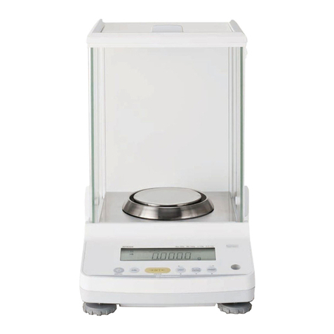
Shimadzu
Shimadzu ATX-R Series User manual
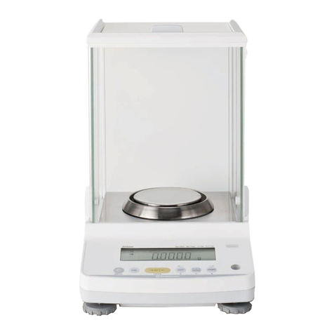
Shimadzu
Shimadzu ATX224 User manual
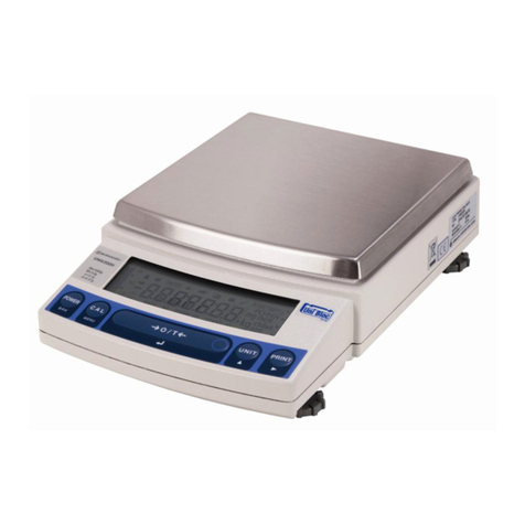
Shimadzu
Shimadzu UW620HV User manual
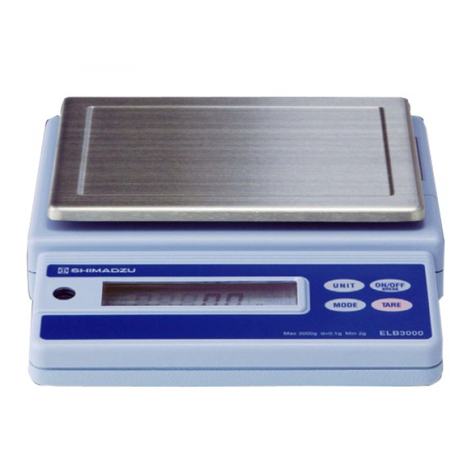
Shimadzu
Shimadzu ELB120 User manual
Shimadzu
Shimadzu UPX Series User manual
Shimadzu
Shimadzu TW223L User manual
Shimadzu
Shimadzu TW Series User manual

Shimadzu
Shimadzu ELB Series User manual
Shimadzu
Shimadzu BL3200H User manual
Shimadzu
Shimadzu UW220H User manual
