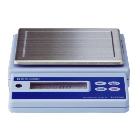
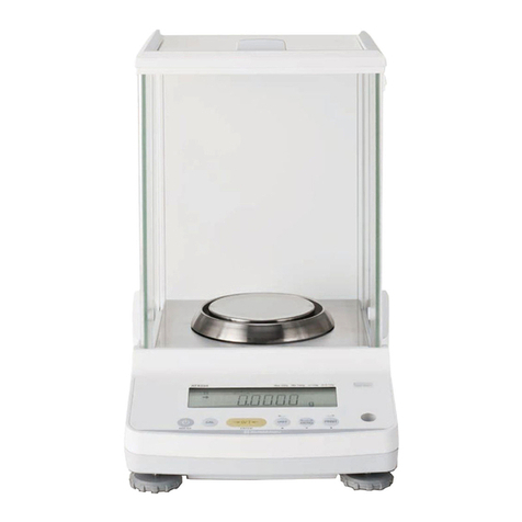
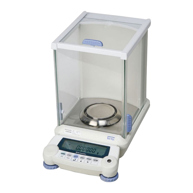
Shimadzu BX32KS User manual

M054-E115C
SHIMADZUCORPORATION
Kyoto,JAPAN
Instruction Manual
For
Medium-Sized Electronic Balance
BX-K series
BX32KS, BX52KS, BX12KH, BX22KH, BX32KH
BW-K series
BW32KS, BW52KS, BW12KH, BW22KH, BW32KH


-76-
Notation Conventions
This instruction manual uses the following notation conventions to indicate Safety
Precautions.
CAUTION
Indicates a potentially hazardous situation that may result in injury to
personnel or equipment damage.
Note: Provides additional information needed to properly use the balance.
Other conventions used in this manual include:
ITEM DESCRIPTION
1) 2) 3)…Indicates the step number in a procedure or a sequence of changes in the balance display.
Indicates the display change or action sequence performed by the balance after an
operation has been initiated.
Refer to the recommended sections for further information on a specific topic.
etc.
Indicates the balance display status.
Underlined portions (_) indicate that the character is blinking.
mass display Indicates the balance is in the weighing mode and mass is displayed in one of the
weighing units.
These sections include information to make using the balance more convenient.
Menu Map
item [1]
Indicates the Menu Map item to be selected.
The number inside the [ ] is the number of the item on the Menu Map.
See Section 2.3 "Menu Map."

-76-
SAFETY PRECAUTIONS
To ensure safe and proper operation of the balance, observe the following precautions.
• Do not use the balance in hazardous areas.
This includes areas where the balance is expose to dust or flammable gases and
liquids.
• Use the AC adapter specified by Shimadzu.
To prevent electric shock, never disassemble the AC adapter.
The AC adapter is designed for indoor use. Do not use the AC adapter in exterior
environments or where it may be splashed by water.
Ensure that the power supply voltage meets the indicated range of the AC adapter.
• Handle the balance carefully.
The balance is a precision instrument of solid design.
• Do not connect peripheral devices other than those recommended by Shimadzu.
The balance may not operate properly if peripheral devices other than those
specified in this manual are used. The specifications for the RS-232C/AUX
connector are described in Section 3.2 "Personal Computer - RS-232C". Connect
the peripheral devices according to the methods described in this instruction
manual.
• DO NOT disassemble the balance, accessories, or peripheral unit.

-76-
1. BASIC OPERATION......................................................................................7
1.1 Balance Components................................................................................................7
1.1.1Operations of the Keys on the Main Unit.....................................................................9
1.1.2Symbol Display..............................................................................................................10
1.2 Installation..............................................................................................................11
1.2.1Choosing the Installation Site...................................................................................11
1.2.2 Balance Installation....................................................................................................11
1.3 Turning the Power ON ...........................................................................................13
1.4 Adjusting the Built-in Clock ....................................................................................14
1.5 Span Calibration ....................................................................................................14
1.6 Weighing................................................................................................................14
1.6.1Changing the Unit Display...........................................................................................15
1.6.2 Changing the Minimum Display Digit( / )........................................15
1.7 Maintaining and Transporting the Balance............................................................15
1.7.1 Cleaning the Balance...................................................................................................15
1.7.2 Transporting the Balance ............................................................................................15
1.8 Specifications.........................................................................................................16
2MEMU ITEM SELECTION.........................................................................17
2.1 Introduction............................................................................................................17
2.2 Procedure of Menu Item Selection.........................................................................17
2.3 Menu Map..............................................................................................................19
2.4 General Menu Operations......................................................................................27
2.4.1Setting Numeric Values...............................................................................................27
2.4.2Setting a Decimal Point................................................................................................27
2.4.3Menu Lock .....................................................................................................................27
2.4.4Last Menu Recall..........................................................................................................28
2.4.5Returning to the Default Settings (menu reset)........................................................28
2.5 Calibration Execution Menu...................................................................................30
2.5.1Calibration.......................................................................................................................30
2.5.2 Span Calibration Using the Built-in Weight, ........................30
2.5.3 Calibration Check Usingthe Built-in Weight ...........................31
2.5.4 Span Calibration Using External Weights ............................................32
2.5.5 Calibration Check UsingExternal Weights ..................................33
2.6 Calibration Setting Menu........................................................................................33
2.6.1Selecting the Standard Calibration Type ( -).................................33
2.6.2PCAL - Calibration of the Built-in Weight -.................................34
2.7 Graphic Display Menu : ...........................................................35
2.7.1Overview.........................................................................................................................35
2.7.2Full Scale Mode ...........................................................................35
2.7.3Target Mode .................................................................................35
2.7.4Group Mode .................................................................................36

-76-
2.7.5Level Mode ...................................................................................36
2.7.6No Graphic Display ......................................................................36
2.8 Environment Menu : ............................................................... 37
2.8.1Overview.........................................................................................................................37
2.8.2Averaging ......................................................................................37
2.8.3Stability Detection Band .................................................................37
2.8.4Tracking ............................................................................................38
2.8.5 Pretaring Value ........................................................................38
2.8.6Whole Lighting Mode .......................................................................39
2.8.7Taring/Printing ...............................................................39
2.9 Application Menu : ................................................................... 41
2.9.1Overview.........................................................................................................................41
2.9.2Zero Range....................................................................................................................41
2.9.3Auto Zero........................................................................................................................42
2.9.4Auto Print........................................................................................................................42
2.9.5Peak Hold.......................................................................................................................43
2.9.6Interval Timer.................................................................................................................44
2.9.7 Auto-Memory and Zeroing..........................................................................................45
2.9.8Animal Weighing...........................................................................................................46
2.10. Unit Registration Menu and Unit Change.............................................................. 47
2.10.1 Unit Registration Menu.............................................................................................47
2.10.2 % Conversion ............................................................................................................47
2.10.3 Piece Counting..........................................................................................................48
2.10.4 Solid Specific Gravity Measurement......................................................................49
2.10.5 Liquid Specific Gravity Measurement....................................................................50
2.11 System Setting Menu : ......................................................... 51
2.11.1 Date for the Built-in Clock.........................................................................................51
2.11.2 Time for the Built-in Clock ..........................................................51
2.11.3 Display During Standby .............................................................51
2.11.4 Measurement Control System .....................................................52
2.12 Communication Menu ( blinking)...................................... 52
2.12.1 Overview.....................................................................................................................52
2.12.2 Handshaking - .........................................................................53
2.12.3 Format ......................................................................................53
2.12.4 Communication Speed ........................................................54
2.12.5 Parity / Bit Length -.....................................................................54
2.12.6 Stop Bit −...................................................................................54
2.12.7 Delimiter ..................................................................................54
3. Connecting Peripheral Instruments........................................................... 55
3.1 EP-60A Electronic Printer...................................................................................... 55
3.2 Personal Computer - RS-232C - ........................................................................... 55
3.2.1Connecting the Cable...................................................................................................55

-76-
3.2.2Data Format...................................................................................................................56
3.2.3Using Command Codes..............................................................................................57
3.2.4Windows® Direct Function..........................................................................................63
3.2.5Multi-Connection Mode................................................................................................65
3.3 Optional AKB-301 Application Keyboard................................................................67
3.3.1Basic Information...........................................................................................................69
3.3.2Example of Use.............................................................................................................70
3.4 Foot Switches ........................................................................................................72
3.5 Hook for Below-Balance Weighing..........................................................................73
4. APPENDIX.................................................................................................74
4.1 Part List..................................................................................................................74
4.1.1Standard Accessories and Maintenance Parts.......................................................74
4.1.2Options............................................................................................................................74
4.2 Table of Unit Conversion Constants.......................................................................75
4.3 Specifications for the RS-232C/AUX Connector....................................................75
4.4 Error Display List....................................................................................................77
4.4.1General Display.............................................................................................................77
4.4.2Error Display ..................................................................................................................77

-76-
INTRODUCTION
Thank you for purchasing this medium-sized electronic balance, the Shimadzu BX-K/ BW-K series.
In addition to its ability to make rapid mass measurements, the BX-K/ BW-K series is also
well-equipped with a four-mode analog display, clock function, various application measurement
functions and a unit conversion function. Furthermore, it is a high performance, multi-functional
balance which can be used in a great variety of applications when connected to peripherals. The
BW-K series features a built-in calibration weight which allows easy sensitivity calibration wherever
you are, making it even more convenient to use.
Before using the balance read this instruction manual carefully to ensure long and fruitful use
of the BX-K/ BW-K series.

-76-
1. BASIC OPERATION
1.1 Balance Components
Open the package and sure following items are included.
Balance body, pan, AC adaptor, Balance cover, adhesive tape,
Instruction manual, inspection certificate,
<BW-K only>
Internal weight, Fix screw of the internal weight, cover of the internal weight
Fix of the screw of the internal cover
[ Name ] [ Appearance ] [ Notes ]
Balance unit
Pan
Built-in calibration
mass
Calibration weight
stopper screw
Calibration weight
cover
Calibration weight
cover setscrew
A
C adapto
r
The serial number of the
balance is stated on this
nameplate
Check that the numerals on
this part are the same as the
last 5 figures of the serial
number on the balance unit
(BWK series only)
(BWK series only)
(BWK series only)
(BWK series only)

-76-
Position of the calibration lever (BW-K series only)
Regardless of whether the calibration lever is in the measurement or calibration
position, ensure that both the left and right levers have been turned until they come to a
stop.
KEY Connector
RS-232C
Connector DATA I/O
Connector DCIN
Connector
Calibration lever (2 places, on the
left and on the right)
(BW-K series only)
Level screws
Level
Display panel
Pan
Balance unit
Key switch
Measurement
position ・・・・・・・・・・・・・・
Calibration
position ・・・・・・・・・・・・・・
Rear of balance
Front of balance

-76-
1.1.1 Operations of the Keys on the Main Unit
The functions of the keys found on the front of the balance are described in the table below.
During Weighing During Menu Selection (*1)
Key
Pressing Once
and Releasing
Pressing and
Holding for
About 3
Seconds
Pressing Once
and Releasing
Pressing and
Holding for
About 3
Seconds
Switches
between the
operation and
standby modes.
Exits the
Application
Measurement
function.
Returns to the
previous menu.
Returns to the
mass display.
Enters span
calibration or
menu selection.
(*2)
Displays the last
Menu Map item
that was set.
(Last menu
recall)
Moves to the
next Menu Map
item.
Displays the last
Menu Map item
that was set.
(Last menu
recall)
Tares the
balance.
(Displays zero.)
(*3)
Displays the
Pretare value.
Selects and sets
the currently
displayed Menu
Map item.
No operation.
Changes the
selected unit.
(*4)
Switches
between the 1d
and 10d display.
(*5)
Increases the
numeric value of
the blinking
digit by 1.
No operation.
Sends the
displayed value
to a peripheral
device.
Sends the date
and time to a
peripheral
device.
Moves to the
next digit during
numeric value
entry.
No operation.
*1 Refer to Section 2. “MENU SELECTION.”
*2 This key is used to set values when percent (%), number (PCS), solid specific
gravity (▼d), or liquid specific gravity (d) units are displayed.
*3 When a Pretare value is set, zero is not displayed and the [- Pretare value] is
displayed.
*4 Units other than “kg” must be registered and set before they can be used for
measurement. Kirogram (kg) is the only unit is registered before shipment. To
register other units, refer to Section 2.10. “REGISTRATION, RELEASE, AND
SELECTION OF MEASUREMENT UNITS”.
*5 When the unit is set to 10d, the resolution of the minimum display is decreased by
one decimal place.

-76-
1.1.2 Symbol Display
An example of “whole lighting” display.
Display Name Description
Stability symbol Indicates that the balance is stable. (*1)
Tare symbol Indicates that a Pretare value has been set.
Zero symbol Indicates that Auto Zero is ON for the Application
Measurement function.
Weight symbol Blinks when span calibration is necessary. This
symbol continues to blink until either a manual or
automatic span calibration has been made.
Number symbol Indicates numeric value entry.
Menu symbol Indicates that the menu lock is on.
* Asterisk Indicates that the displayed numeric value is not a
mass value.
Animal symbol Illuminates when Animal Weighing is ON for the
Application Measurement function.
Auto-Memory &
Zeroing symbol
Illuminates when Auto-Memory and Zeroing are ON
for the Application Measurement function.
Memory symbol Indicates that Net Total Weighing is ON for the
Application Measurement function.
Communication
symbol
Illuminates during communication to external
equipment through the RS-232C or DATA I/O
connector.
Battery symbol When the balance is operated with the optional
battery pack, this symbol illuminates to indicate that
the battery voltage has dropped.
AP Auto Print symbol Indicates that Auto Print is ON for the Application
Measurement function.
Stand-by symbol Illuminates when the balance power is in the standby
mode.
This symbol also illuminates when the Application
Measurement function has entered the standby mode.
▼
Inverse triangle
symbol
Illuminates when the solid specific gravity unit is
used. This symbol is also used as a substitute for the
decimal point.
*1 Stability symbol
The displayed value may change while the stability symbol remains illuminated if
the load is changing slowly or if the stability detection band has been set to a large
value.
Graphic display
Unit display

-76-
1.2 Installation
1.2.1Choosing the Installation Site
(1) Power supply
CAUTION
• Select an installation site that is near a power source to
ensure that the attached AC adapter is used properly. If this is
not possible, an optional battery pack is available as a special
accessory.
• Verify that the supply power voltage conforms to that
indicated on the AC adapter.
(2) Installation site
CAUTION
Choose an installation site where the balance will be protected
from the following:
• corrosive or flammable gasses.
• dust, wind, vibration, electromagnetic waves, or magnetic
fields.
• direct sunlight.
• extreme temperature or humidity.
• rain or the possibility of being splashed with water.
Large capacity balances should be installed on a sturdy floor and
table that can withstand the total load of the balance AND object
to be weighed.
1.2.2 Balance Installation
1) Put the balance onto its side and unscrew the 2
transportation screws in accordance with the instruction
label on the bottom of the balance. Screw these into the
“Release” hole.
2) Place the balance unit as shown in the diagram on the
right. If intending to fit the vinyl cover, fix it at this
Release hole
Instruction label

-76-
stage of the procedure. Refer to “Fitting the Vinyl Cover”, mentioned later.
3) Fix the calibration weight cover (1) with the
calibration mass cover setscrew (2).
Note
Steps (3) to (5) are only required with the BW-K
series.
4) Put the built-in calibration weight (3) in place and
tighten the calibration weight stopper screw (4).
5) Turn both the left and right calibration levers of
the pan to the Measurement position.
6) Place the pan on the balance. For the BW-K series, the
pan will be easier to place if it is placed slightly from
the rear.
7) The level of the balance is adjusted Note.
Turn the level screws to adjust it so that the air bubble in the level rests inside the red
circle. Check that the balance is steady when adjustment is complete.
Note
Adjusting the level can be done with ease if all 4 level screws are at first
grounded equally. Next, adjust the front and the back using the 2 front feet, and
then adjust left and right using either of the 2 feet on the left and right.
1.2.2.1Fitting the Vinyl Cover
When using the balance in a location where it is likely to get dirty easily, refer to the
diagram below and affix a vinyl cover by following the procedure below. Remove
the pan first if fitting the vinyl cover after the balance has been assembled.
1) Cut the supplied tape (2) and stick it onto the 4 points on the case (3) (refer to the
diagram below).
2) Fix the vinyl cover (1) onto the double-sided tape (2), ensuring that there are no
creases.
Measurement

-76-
3) Fit the pan.
4) Place a weight onto the pan which is close to the weighing capacity to check that the
pan and vinyl cover are not touching. Accurate measurements cannot be made if there
is contact between the two items. If this is the case, re-fix the vinyl cover.
(Note) The vinyl cover (1) is folded up when it is in the packaging.
1.3 Turning the Power ON
1) Insert the plug of the AC adapter into the DC IN connector on the rear of the
balance, then insert the AC adapter into the power source.
Note: When using the optional battery pack (special accessory), connect the fully
charged battery pack to the DC IN connector of the balance using the cable
attached to the battery pack.
2) The balance self-check is activated and the following messages are displayed in the
order indicated.
Ver. No.
Whole lighting
(and are not displayed for the BX series.)
3) When the
key is pressed, the whole display illuminates and then the display
changes to indicate the kilogram-display.
Note
If ENVIRONMENT menu 37 has been selected, the
display stops in the whole lighting state. In this case, press the
key
during whole lighting to change the display to the kilogram-display.

-76-
1.4 Adjusting the Built-in Clock
The BX-K and BX series of balances have a built-in battery driven clock. After unpacking
and installing the balance, adjust this clock to the appropriate date and time.
Refer to Section 2.11.1 “Date for the Built in Clock.”
Refer to Section 2.11.2 “Time for the Built-in Clock.”
1.5 Span Calibration
It is necessary to calibrate the balance after it is moved, or when the ambient temperature has
changed.
Verify that the balance is stable before performing the span calibration. To achieve a very
stable state, ensure that the balance has been turned on for at least one hour, that the
temperature is constant, that there are no breezes or vibrations and that the balance is in an
area isolated from the normal traffic flow.
Refer to the following sections for more information on the Span Calibration procedure.
For BX-K series balances, refer to Section 2.5.2 “Span Calibration Using the Built-in
Weight.”
For BX series balances refer to Section 2.5.4 “Span Calibration Using External
Weights.”
1.6 Weighing
1) Place the weigh vessel (tare) on the pan.
2) Press the key to zero the display.
Note
If a Pretare value is set, the symbol is illuminated and zeroing of the display does not occur.
3) Place the object to be weighed on the pan, and read the displayed value after the
stability symbol is displayed.
Errors Displayed During Weighing
Overload: Weighing capacity has been exceeded.
Negative Overload: The load on the balalnce is too light.
The pan is not adjusted properly.
Display Overload: This display appears if the mass display
exceeds 7 digits due to the choice of unit.
May appear after the key is pressed while the solid
specific gravity (▼d)or liquid specific gravity (d) units are used.

-76-
1.6.1 Changing the Unit Display
Every time the key is pressed, the unit display changes sequentially among those
registered in the UNIT REGISTRATION menu.
Note: Before a unit can be displayed it must be registered in the UNIT REGISTRATION
menu. Refer to “2.10 Unit Registration Menu and Unit Change” for information on
how to register units.
The unit is displayed sequentially according to the order of the UNIT
REGISTRATION menu.
1.6.2 Changing the Minimum Display Digit(/)
It is possible to decrease the resolution of the minimum balance display by one decimal place
if necessary.
1) Press and hold the key for approximately three seconds. is displayed
and the display is decreased by one decimal place.
2) Press and hold the key for approximately three seconds. is displayed and
the display returns to the original number of decimal places.
1.7 Maintaining and Transporting the Balance
1.7.1 Cleaning the Balance
Use a soft damp cloth containing a neutral detergent to clean the balance.
Avoid using organic solvents, chemicals, or dusting sprays as they may damage the coatings
of the balance or the display panel.
Attach the in-use balance cover (standard accessory) when the balance is used in an
environment where it is susceptible to being soiled.
The pan can be removed and washed with water. Verify that the pan is completely dry before
replacing it on the balance.
1.7.2 Transporting the Balance
To carry the balance, hold the balance firmly with both hands.
To transport the balance, use the shipping carton used to deliver the balance.
Before placing the balance into the shipping carton, verify that the transportation screws at
the bottom of the balance have been tightened until they stop.

-76-
1.8 Specifications
Type
Weighing
Capacity
(kg)
Minimum
Display (g)
Standard
Deviation
(σ≦)g
Linearity
±g
Range of
the External
Calibration
Weight (kg)
BX32KS
BW32KS 32 1 0.6 1 30
BX52KS
BW52KS 52 1 0.6 1 50
BX12KH
BW12KH 12 0.1 0.1 0.2 10
BX22KH
BW22KH 22 0.1 0.1 0.2 20
BX32KH
BW32KH 32 0.1 0.12 0.2 30
The BX-K series is not equipped with a built-in calibration weight.
The BW-K series is equipped with a built-in calibration weight.
Temperature coefficient of sensitivity:
H-type = ± 4ppm/°C
S-type = ± 5ppm/°C (Range of temperature compensation: 10 to 30°C)
Common Specifications
BW-K BX-K
Pan size (mm) Approx.345 W x 250 D
Dimensions Approx.360 W x 355 D x 125 H
Weight (kg) Approx.16.5kg Approx 10.5kg
Operating
Temperature
Range
5 - 40℃
Power Supply AC adapter (AC100V) or battery pack (special accessory)
RS-232C connector for RS-232C
I/O Connector DATAI/O connector for Electronic Printer, Printer
KEY connector for application keyboard AKB-301

-76-
2 MEMU ITEM SELECTION
2.1 Introduction
The BX-W and BW-K series balance has many functions that can be selected to meet the
requirements of the user. Menu Item selection is used to program these functions.
The symbol is displayed during Menu Item selection.
Once the menu items have been set based on the installation environment and weighing
purpose, it is not necessary to select the menu items each time the balance is used. Once
the contents of the menu are set, they are stored even if the balance is turned OFF or if the
power is disconnected.
2.2 Procedure of Menu Item Selection
The menu of the BX-W / BW-K balance consists of four levels.
1) Press the key to cycle through the items within a menu level.
( in the table below)
2) Press the key to choose the current item or move to the next menu
level.
( in the table below)
3) Press the key to move back one menu level.
4) Press and hold the key to return to the mass display.
This instruction manual identifies each menu item by a number. For example,
, “Anti-Vibration mode” is identified as [25].
Refer to Section 2.3 "Menu Map" or the attached operation explanatory sheet.

-76-
Symbols in the : Display
Press the key when the following symbols are blinking to enter the
associated menu.
(Calibration) = Enters the menu related to span
calibration.
(Graphic display) = Enters the menu related to the graphic
display, target and checkweighing.
(Environment) = Enters the menu related to the installation
environment and general operation of the
balance.
(Application) = Enters the menu related to applications and
printing.
(Unit) = Enters the menu related to unit conversion.
(System) = Enters the menu related to the system
(clock, reports, and passwords).
(Communication) =Enters the menu related to communication
with a computer and software.
The stability symbol in the : display indicates that
, , and are set.
This manual suits for next models
9
Table of contents
Other Shimadzu Scale manuals

Shimadzu
Shimadzu TW Series User manual

Shimadzu
Shimadzu ELB120 User manual

Shimadzu
Shimadzu ATX-R Series User manual

Shimadzu
Shimadzu UW620HV User manual

Shimadzu
Shimadzu BL3200H User manual

Shimadzu
Shimadzu ATX224 User manual

Shimadzu
Shimadzu UPX Series User manual

Shimadzu
Shimadzu ELB Series User manual

Shimadzu
Shimadzu AW Series User manual

Shimadzu
Shimadzu AUW220D User manual