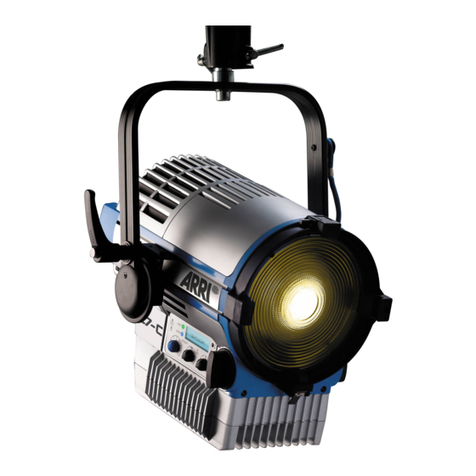
Grundfunktionen
BEFESTIGUNG
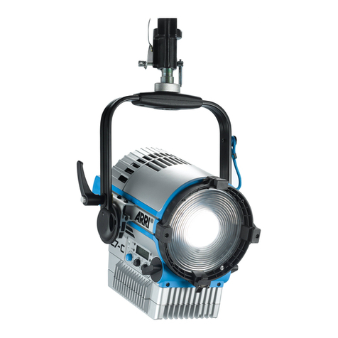
Der Scheinwerfer darf nur an seinem Haltebügel (5) stehend oder
hängend befestigt werden. Schieben Sie den Stativzapfen (12) in die
Hülse eines passenden Stativs oder einer passenden Haltevor-
richtung und klemmen Sie ihn fest. Sichern Sie den Zapfen gegen
Herausfallen. Sie können 28 mm Aufnahmen oder 16 mm Zapfen
verwenden.
DREHEN UND NEIGEN
Sie können den Scheinwerfer nach Lösen der Schraube am Stativ
oder der Haltevorrichtung drehen. Verändern Sie die Neigung nach
Lösen der Bügelklemmung (13). Ziehen Sie alle Schrauben nach dem
Einrichten des Scheinwerfers fest an.
EINSTELLEN DES ABSTRAHLWINKELS
Durch Drehen des Fokusknopfes (8) können Sie den Abstrahlwinkel
stufenlos verändern. Dabei bewegt sich der gesamte Linsentubus aus
dem Gehäuse heraus bzw. in das Gehäuse hinein. Dieser Mechanis-
mus besitzt zwei Schutzfunktionen:
Eine Sollbruchstelle verhindert Schäden am Gerät, falls der
Fokusknopf mit einem zu hohem Drehmoment bewegt wird.
Deshalb Fokusknopf nur mit der Hand drehen und bei Stillstand
des Tubus stoppen!
Ein selbsthemmendes Getriebe verhindert, dass sich die Position
des Tubus bei geneigtem Scheinwerfer verändert.
VERWENDUNG VON ZUBEHÖR FÜR DIE LICHTFORMUNG
Zubehör für die Lichtformung, wie z.B. ein Flügeltor oder ein
Filterhalter mit einem Diffusor, kann in die Halteklauen auf der
Vorderseite des Scheinwerfers eingesetzt werden:
Drücken Sie den Knopf an der Seite der Torsicherung fest. Die
Torsicherung klappt nach oben auf.
Schieben Sie das Zubehör von oben in die Halteklauen, bis der
Rasthaken (15) einrastet. Zur Unterstützung kann der Rasthaken
etwas mit dem Finger gekippt werden.
Klappen Sie die Torsicherung (7) zu und achten Sie darauf, dass
die Nase in den Haltering des Zubehörteils einrastet.
DMX-SCHNITTSTELLE
Der Scheinwerfer verfügt über eine zwei 5-polige, verriegelbare XLR-
Verbinder für den DMX / RDM Datenein- und –ausgang. Der 4-polige
XLR-Verbinder dient zum Anschluss einer Versorgungsbatterie. Die
Pole 2 und 3 des Verbinders können als DMX / RDM Dateneingang
verwendet werden.
ACHTUNG –Verwenden Sie nur einen DMX / RDM Dateneingang
gleichzeitig. Das Gerät kann beschädigt werden oder falsch auf
Steuerbefehle reagieren, wenn Sie beide Dateneingänge gleichzeitig
verwenden.
USB-SCHNITTSTELLE
Der Scheinwerfer besitzt eine USB-Schnittstelle mit einer Mini-USB-
Buchse für das Aufspielen von Firmware, die Einstellung von
Betriebsparametern und für Servicezwecke. Ein kostenlos erhältliches
Service-Tool für den PC erlaubt die Steuerung bzw. Programmierung
des Scheinwerfers über diese Schnittstelle.
Die neueste Firmware sowie den L-Series Manager finden Sie im
Download-Bereich der Internetseite www.arri.com.
EINSCHALTEN UND BETRIEB
Mit dem Einschalten des Netzschalters (bzw. nach dem Anlegen der
Netzspannung bei Scheinwerfern ohne Schalter) beginnt der
Scheinwerfer nach kurzer Verzögerung mit derjenigen Einstellung, die
bei der letzten Abschaltung aktiv war, zu leuchten.
Der Scheinwerfer kann nun über die DMX-Schnittstelle, über die
USB-Schnittstelle oder über das Bedienfeld gesteuert werden.
Basic Functions
MOUNTING
The fixture must be mounted on its stirrup (5) in a standing position or
a hanging position. For this, insert the spigot (12) into the bushing of a
suitable stand or a suitable clamping system and fix and secure the
spigot afterwards. You might use 28 mm bushings or 16 mm spigots
to mount the fixture.
PAN AND TILT
The fixture can be panned after loosening the screw of the stand or
the clamping system. The tilt angle can be adjusted by releasing the
tilt lock (13). After the adjustment of the pan angle and the tilt angle,
the screws resp. clamps must be fastened again.
ADJUSTING THE BEAM ANGLE
The beam angle can be continuously adjusted by turning the focus
knob (8). In doing so, the lens tube will move into and out of the
housing. This mechanism contains two protective functions:
A predetermined breaking point protects the fixture from damage if
the focus knob is being turned with overly strong force. Therefore
only turn the focus knob by hand and stop when the lens tube has
reached full extension or retraction!
A self-inhibiting gear avoids the inadvertent movement of the lens
tube when the fixture is in a tilted position.
USE OF LIGHT SHAPING ACCESSORIES
Light shaping accessories like a barndoor or a filter frame with a
diffusing material can be inserted into the clamps at the front of the
fixture:
Press the knob on the side of the top latch (11) firmly. The top
latch opens upwards.
Slide the accessory from above into the clamps until the safety
catch (15) engages. To support this, the safety hook can be
slightly tilted with a fingertip.
Close the top latch (7) and take care that the nose engages in the
retaining ring of the accessory.
DMX INTERFACE
The fixture is equipped with two locking, 5-pin XLR connectors for the
DMX / RDM data input. The 4-pin XLR connector serves as a
connector for a battery pack. The pins 2 and 3 might be used as a
DMX / RDM data input.
ATTENTION –Do not use both DMX / RDM inputs at a time. The
fixture might be damaged and behave erratically on control
commands if it receives control data on both inputs.
USB INTERFACE
The fixture is equipped with an USB interface (Mini USB connector).
The interface can be used for uploading new firmware, setting the
operating parameters or for service purpose. A service tool for
Windows PCs allows the control and programming of the fixture over
this interface.
The latest firmware and L-Series Manager software tool are located in
the download area of our website www.arri.com.
POWER-ON AND OPERATION
By switching the power switch on (or by applying the mains power on
fixtures without a switch), the fixture starts lighting after a short startup
time with the same setting which had been active at its last switch off.
The fixture can now be controlled over the DMX interface, over the
USB interface or by the control panel.
