ShowPro H1 PROFILE User manual

1
H1 PROFILE
MANUAL
PSHMOV100

2
CONTENTS
SAFETY - - - - - - - - - - - - - - - - - - - - - - - - - - - - - - - - - - - - - - - - - - - - - - - - - - - - - - - - - - - - - - - - - - 3
INTRODUCTION - - - - - - - - - - - - - - - - - - - - - - - - - - - - - - - - - - - - - - - - - - - - - - - - - - - - - - - - - - - - 4
SPECIFICATIONS - - - - - - - - - - - - - - - - - - - - - - - - - - - - - - - - - - - - - - - - - - - - - - - - - - - - - - - - - - - 5
PHOTOMETRICS - - - - - - - - - - - - - - - - - - - - - - - - - - - - - - - - - - - - - - - - - - - - - - - - - - - - - - - - - - - 6
COLOUR & GOBOS - - - - - - - - - - - - - - - - - - - - - - - - - - - - - - - - - - - - - - - - - - - - - - - - - - - - - - - - - 7
DIMENSIONS - - - - - - - - - - - - - - - - - - - - - - - - - - - - - - - - - - - - - - - - - - - - - - - - - - - - - - - - - - - - - - 8
OVERVIEW - - - - - - - - - - - - - - - - - - - - - - - - - - - - - - - - - - - - - - - - - - - - - - - - - - - - - - - - - - - - - - - - 9
INSTALLATION - - - - - - - - - - - - - - - - - - - - - - - - - - - - - - - - - - - - - - - - - - - - - - - - - - - - - - - - - - - - 10
CONNECTION - - - - - - - - - - - - - - - - - - - - - - - - - - - - - - - - - - - - - - - - - - - - - - - - - - - - - - - - - - - - - 11
MENU - - - - - - - - - - - - - - - - - - - - - - - - - - - - - - - - - - - - - - - - - - - - - - - - - - - - - - - - - - - - - - - - - - - 13
DMX CHART - - - - - - - - - - - - - - - - - - - - - - - - - - - - - - - - - - - - - - - - - - - - - - - - - - - - - - - - - - - - - - 15
MAINTENANCE - - - - - - - - - - - - - - - - - - - - - - - - - - - - - - - - - - - - - - - - - - - - - - - - - - - - - - - - - - - - 17
TROUBLESHOOTING - - - - - - - - - - - - - - - - - - - - - - - - - - - - - - - - - - - - - - - - - - - - - - - - - - - - - - - 17

3
SAFETY
WARNING! Before carrying out any operations with the unit, carefully read this instruction
manual and keep it with care for future reference, it contains important information about the
installation, use and maintenance of the unit.
General instructions
- The products referred to in this manual conform to the European Community Directives and
are therefore marked with CE.
- The unit is supplied with hazardous network voltage (230V~). Leave servicing to skilled
personnel only. Never make any modifications on the unit not described in this instruction
manual, otherwise you risk an electric shock.
- Connection must be made to a power supply system fitted with efficient earthing (Class I
appliance according to standard EN60598-1). It is recommended to protect the supply lines
of the units from indirect contact and/or shorting by using appropriately sized residual current
devices.
- The connection to the main network of electric distribution must be carried out by a
qualified electrical installer. Check that the mains frequency and voltage correspond to those
for which the unit is designed as given on the electrical data label.
- This unit is not for home use, only use for professional applications.
- Never use the fixture under the following conditions:
• in places subject to vibrations or bumps;
• in places with a temperature of over 40 ℃.
- Make certain that no flammable liquids, water or metal objects enter the fixture.
- Do not dismantle or modify the fixture.
- All work must always be carried out by qualified technical personnel. Contact the nearest
sales point for an inspection or contact the manufacturer directly.
- If the unit is to be put out of operation definitively, take it to a local recycling plant for a
disposal which is not harmful to the environment.

4
Warnings and installation precautions
- If this device is operated in any way different to the way described in this manual, it may
suffer damage and the warranty becomes void. Any unauthorized operation may lead to
dangers like short circuit, burns, electric shock, etc.
- Before starting any maintenance work or cleaning the fixture, cut off power from the main
supply.
- Always additionally secure the fixture with a safety chain. When carrying out any work,
always comply scrupulously with all the regulations (particularly regarding safety) currently in
force in the country in which the fixture is being used.
- Install the fixture in a well-ventilated place.
- Keep any flammable materials at a safe distance from the fixture.
- Shields, lenses or ultraviolet screens shall be changed if they have become damaged to
such an extent that their effectiveness is impaired.
- The lamp shall be changed if it has become damaged or thermally deformed.
- Never look directly at the light beam. Note that fast changes in lighting, e.g. flashing lights,
may trigger epileptic seizures in photosensitive persons or persons with epilepsy.
- Do not touch the product’s housing when operating because it may be very hot.
INTRODUCTION
Features
• A perfect combination of beam/spot/wash with HID light source
• 480w 6500K PHILIPS lamp
• Ultra-bright output of 130K lux @ 20m
• Crisp beam from lens to end at every beam angle
• Consistent brightness from centre to edge
• 2.1°~41.5° wide zoom angle
• CMY colour mixing (CMY+15 filters)
• 19 fixed gobos + 8 rotating gobos
• 1 animation wheel
• Bi-directional 4-facet and 8-facet prisms with variable speed
• DMX and RDM control

5
SPECIFICATIONS
Light Source: 480W PHILIPS lamp
Output: 16300lm
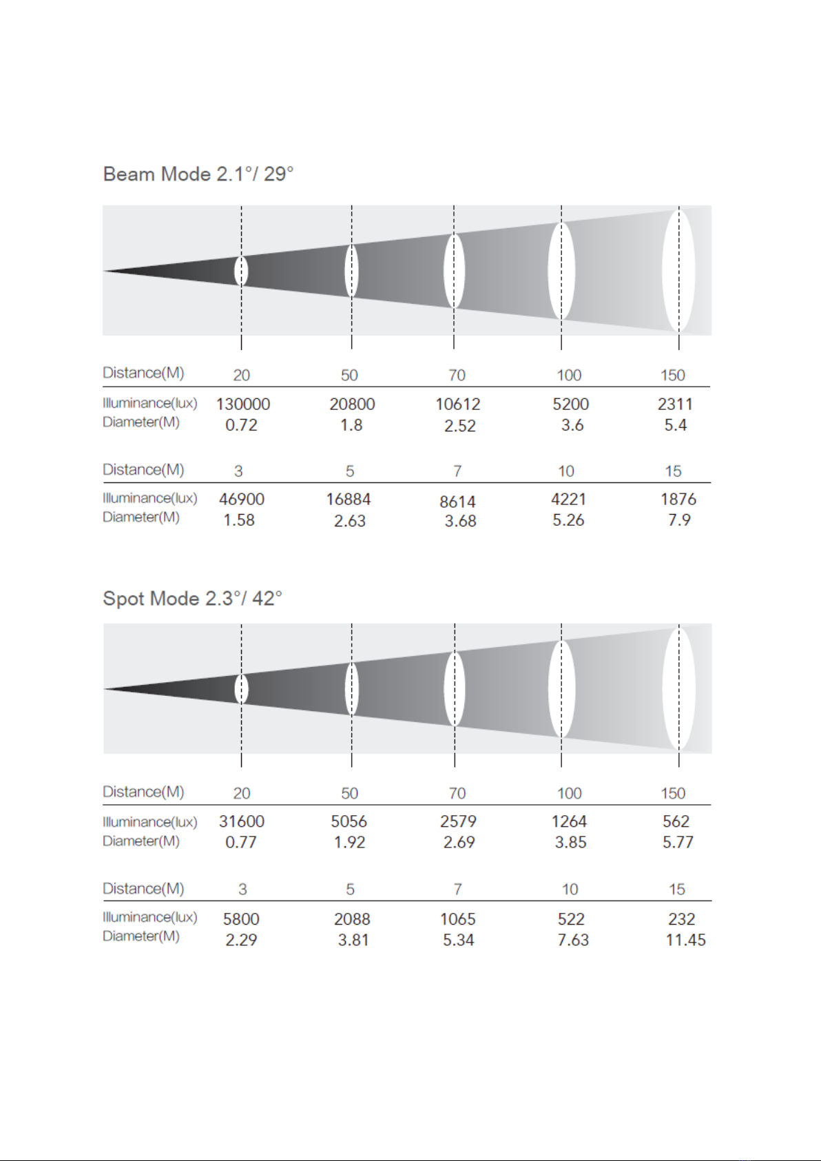
Illuminance: 130k @ 20m
Colour Temperature: 6500K ± 400K
Beam Angle: Beam mode: 2.1°~29° Spot mode: 2.3°~41.5°
Pan: 540° (16 bit)
Tilt: 270° (16 bit)
Colour: CMY + 15 filters
Gobos: 1 static gobo wheel (19 + open)
1 rotating gobo wheel (8 + open)
Animation: 1 animation wheel
Focus: Motorized focus
Frost: 10° frost
Strobe: 0~12Hz
Dimming: 0~100%
Prism: 4-facet and 8-facet bi-directional, indexable rotating
Protocol: DMX512/RDM
DMX Channels: 31CH
Data Connections: XLR In/Out for DMX
Display: TFT Display
Mains: 100~240 VAC, 50/60 Hz
Consumption: 650W/230V
Power Connections: TRUECON In
Materials: Aluminium alloy
Finish: Matte black
Ambient Temp: -10℃~45℃
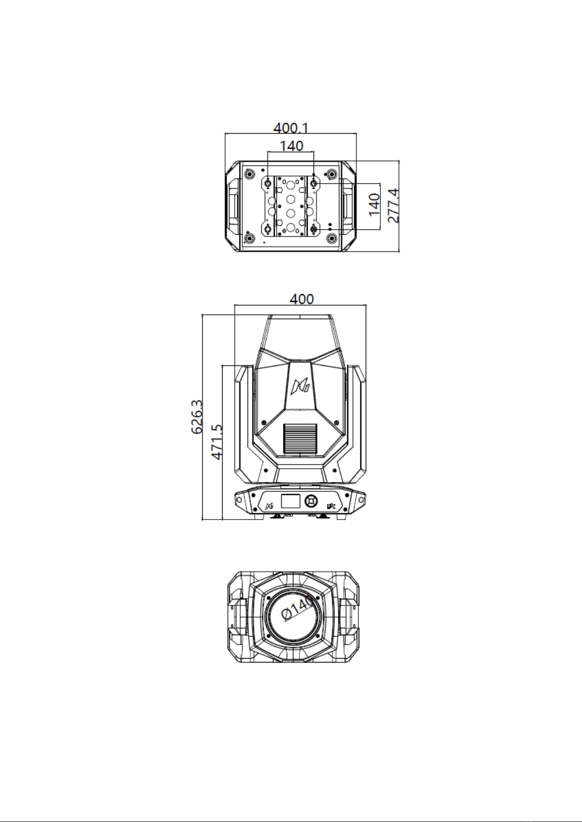
Dimensions: 400.1 x 277.4 x 626.3 mm
Weight: 25kg
6
PHOTOMETRICS

7
COLOUR & GOBOS
Colour
Animation
Rotating Gobos
Static Gobos
8
DIMENSIONS

9
OVERVIEW
Fixture Illustration
1. Control Panel 4. Fuse
2. 3/5 Pin DMX In 5. Power In
3. 3/5 Pin DMX Out 6. Omega Bracket Plate
Control Panel
UP:Increase value or scroll up
DOWN: Decrease value or scroll down
LEFT: Return to previous menu
RIGHT: Move between units, tens, hundreds
OK:Confirm and save setting

10
INSTALLATION
The H1 must be set up on a solid and even surface.
By means of the brackets on the baseplate, the unit can also be mounted upside down to a
cross arm. For mounting, strong, stable clamps are required.
The bolts of the brackets are placed into the openings provided in the base plate and turned
clockwise until they lock.
Always ensure that the unit is firmly fixed to avoid vibration and slipping while operating.
The mounting place must be of sufficient stability and be able to support a weight of 10 times
the unit’s weight.
When carrying out any installation, always comply scrupulously with all the regulations
(particularly regarding safety) currently in force in the country in which the fixture is being
used.
Always additionally secure the fixture with a safety chain. For this purpose, fasten the safety
chain in a suitable position so that the maximum fall of the fixture will be 20 cm.
11
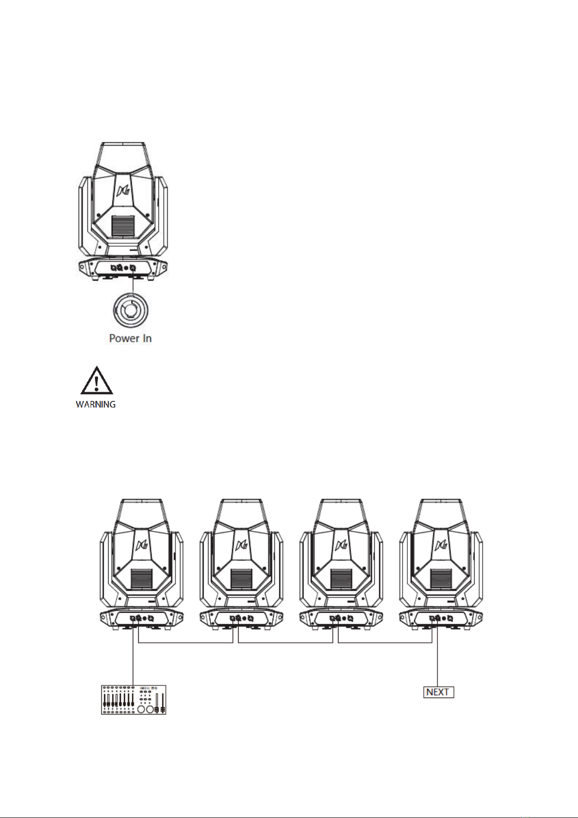
CONNECTION
Power Connection
Using Powercon In.
Attention: due to power rating, one power cable can connect 1 unit
maximum
Do not connect more than 1 units in series with one power cable.
Do not use with damaged power cable.
Power off the fixture when not in use.
DMX Connection

12
•Depending on the length of the DMX cable run, or other factors, it may be advisable
to install a terminator at the last fixture in the run.
•The illustration below shows the correct placement of a 120Ω 0.25W resistor in a
terminator, as well as the standard DMX signal pin connections
DMX Starting Address
•To set the starting address of each fixture:
•Press the ENTER button and use the UP/DOWN buttons to scroll the menu
•Select the CONNECT menu and press ENTER
•Use the UP/DOWN buttons to scroll to the ADDRESS menu
•Press ENTER and use the UP/DOWN buttons to select the DMX address
•Press ENTER to con-rm the chosen DMX address
•Press the MENU button to save changes and exit
Example of DMX Addressing
The below table shows an example of starting addresses for four fixtures assuming a first
fixture with starting address of 001.
MODE
ALLOCATION
ADDRESS
1st Fixture
ADDRESS
2nd Fixture
ADDRESS
3rd Fixture
ADDRESS
4th Fixture
31CH
001 – 031
001
032
063
094
Follow above method for subsequent fixtures, calculating address as indicated.
13
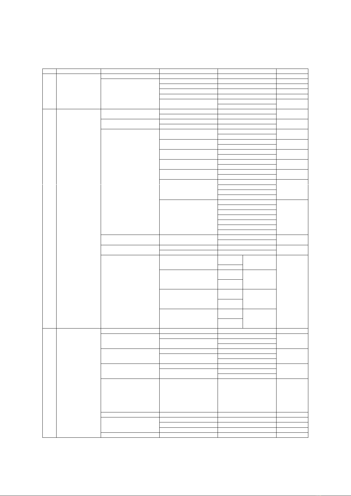
MENU
NO.
Main Menu
Menu Level 1
Menu Level 2
Menu Level 3
Default
1
SETUP
DMX Address
1 – 512
1
Ethernet Interface
Custom IP Address
2.x.x.x
Custom IP Mask
255.0.0.0
Universe
000 – 255
0
Start Channel
1 – 512
1
Ethernet to DMX
No
No
Yes
2
OPTION
Lamp DMX
On
On
Off
Safety Black Out
On
On
Off
Pan/Tilt
Invert Pan
Off
Off
On
Invert Tilt
Off
Off
On
Swap Pan/Tilt
Off
Off
On
Encoder Pan/Tilt
Off
On
On
P/T Homing Mode
Standard
Standard
Sequenced
Pan Home Def Pos
0°
270°
90°
180°
270°
Tilt Home Def Pos
0%
50%
12.5%
25%
50%
75%
87.5%
100%
Shutter
Shutter On Error
On
Off
Off
Display
Off
Off
On
Setting
Default Preset
Reset to
Default
Are you sure?
Yes/No
Go Back
User Preset 1
Load
Preset 1
Are you sure?
Yes/No
Save to
Preset 1
User Preset 2
Load
Preset 2
Are you sure?
Yes/No
Save to
Preset 2
User Preset 3
Load
Preset 3
Are you sure?
Yes/No
Save to
Preset 3
3
INFORMATION
System Errors
Fixture Hours
Total Hours
Partial Hours
Reset
Go Back
Lamp Hours
Total Hours
Partial Hours
Reset
Go Back
Lamp Strikes
Total Strikes
Partial Strikes
Reset
Go Back
System Version
DISP
NET
CTR1 – XY
CTR2 – MOTOR
CTR3 – MOTOR
CTR4 – MOTOR
CTR5 – MOTOR
DMX Monitor
Network Parameters
IP Address
2.x.x.x
IP Mask
255.0.0.0
MAC Address
54–10–EC–5B–B2–32
UID
030F046******

14
NO.
Main Menu
Menu Level 1
Menu Level 2
Menu Level 3
Default
4
MANUAL
CONTROL
Lamp
On
Off
Off
Reset
No
Yes
Channel
1.Cyan
0 – 255
2.Magenta
0 – 255
3.Yellow
0 – 255
4.Colour 1
0 – 255
5.Colour 2
0 – 255
6.Colour 3
0 – 255
7.Strobe
0 – 255
8.Dimmer
0 – 255
9.Dimmer Fine
0 – 255
10.Fixed Gobo
0 – 255
11.Effect
0 – 255
12.REffect
0 – 255
13.Rotating Gobo
0 – 255
14.Gobo Rotation
0 – 255
15.Gobo R Fine
0 – 255
16.4 Prism Insertion
0 – 255
17.4 Prism Rotation
0 – 255
18.8 Prism Insertion
0 – 255
19.8 Prism Rotaton
0 – 255
20.Frost
0 – 255
21.Zoom
0 – 255
22.Focus
0 – 255
23.Focus Fine
0 – 255
24.Beam Mode
0 – 255
25.Pan
0 – 255
26.Pan Fine
0 – 255
27.Tilt
0 – 255
28.Tilt Fine
0 – 255
29.Reset
0 – 255
30.Function
0 – 255
31.Lamp Control
0 – 255
5
TEST
Pan/Tilt
Colour
Beam
Gobo
All
6
ADVANCED
Access Code
(Default: 1234)
Calibration
Pan Offset
0 – 255
Tilt Offset
0 – 255
Dimmer Offset
0 – 255
Cyan Offset
0 – 255
Magenta Offset
0 – 255
Yellow Offset
0 – 255
Gobo1 Offset
0 – 255
RGobo1 Offset
0 – 255
Gobo2 Offset
0 – 255
4 Prism Offset
0 – 255
4 RPrism Offset
0 – 255
8 Prism Offset
0 – 255
8 RPrism Offset
0 – 255
Effect Offset
0 – 255
Focus Offset
0 – 255
Zoom Offset
0 – 255
Frost Offset
0 – 255
Balance Offset
0 – 255
Menu Locking
Unlock Code
xxxx
1234
15
DMX CHART
31CH
Function
Value
Setting
Notes
1
Cyan
0 – 255
Cyan 0% - 100%
Valid when Colour 1 = 0
2
Magenta
0 – 255
Magenta 0% - 100%
Valid when Colour 2 = 0
3
Yellow
0 – 255
Yellow 0% - 100%
Valid when Colour 3 = 0
4
Colour 1
000 – 023
Open
024 – 046
Open + Colour 1
047 – 069
Colour 1
070 – 092
Colour 1 + Colour 2
093 – 115
Colour 2
116 – 139
Colour 2 + Colour 3
140 – 162
Colour 3
163 – 185
Colour 3 + Colour 4
186 – 208
Colour 4
209 – 231
Colour 4 + Colour 5
232 – 255
Colour 5
5
Colour 2
000 – 023
Open
024 – 046
Open + Colour 1
047 – 069
Colour 1
070 – 092
Colour 1 + Colour 2
093 – 115
Colour 2
116 – 139
Colour 2 + Colour 3
140 – 162
Colour 3
163 – 185
Colour 3 + Colour 4
186 – 208
Colour 4
209 – 231
Colour 4 + Colour 5
232 – 255
Colour 5
6
Colour 3
000 – 023
Open
024 – 046
Open + Colour 1
047 – 069
Colour 1
070 – 092
Colour 1 + Colour 2
093 – 115
Colour 2
116 – 139
Colour 2 + Colour 3
140 – 162
Colour 3
163 – 185
Colour 3 + Colour 4
186 – 208
Colour 4
209 – 231
Colour 4 + Colour 5
232 – 255
Colour 5
7
Strobe
000 – 003
Closed
004 – 103
Slow to Fast Strobe
104 – 107
Open
108 – 207
Pulse Slow to Fast
208 – 212
Open
213 – 251
Random Strobe
252 – 255
Open
8
Dimmer
000 – 255
Dimmer 0% - 100%
9
Dimmer Fine
000 – 255
Dimmer Fine
10
Fixed Gobo
000 – 003
Open
004 – 007
Gobo 1
008 – 010
Gobo 2
011 – 014
Gobo 3
015 – 017
Gobo 4
018 – 021
Gobo 5
022 – 024
Gobo 6
025 – 028
Gobo 7
029 – 031
Gobo 8
032 – 035
Gobo 9
036 – 039
Gobo 10
040 – 042
Gobo 11
043 – 046
Gobo 12
047 – 049
Gobo 13
050 – 053
Gobo 14
054 – 056
Gobo 15
057 – 060
Gobo 16
061 – 063
Gobo 17
064 – 067
Gobo 18
068 – 071
Gobo 19
072 – 113
Fast to Slow (Reverse Spin)
114 – 117
Stop (Stop Rotation)
118 – 159
Slow to Fast (Forward Spin)
160 – 165
Gobo 1 Shake Slow to Fast
166 – 170
Gobo 2 Shake Slow to Fast
171 – 175
Gobo 3 Shake Slow to Fast
176 – 180
Gobo 4 Shake Slow to Fast
181 – 185
Gobo 5 Shake Slow to Fast
186 – 190
Gobo 6 Shake Slow to Fast
191 – 195
Gobo 7 Shake Slow to Fast
16
31CH
Function
Value
Setting
Notes
10
Fixed Gobo
196 – 200
Gobo 8 Shake Slow to Fast
201 – 205
Gobo 9 Shake Slow to Fast
206 – 210
Gobo 10 Shake Slow to Fast
211 – 215
Gobo 11 Shake Slow to Fast
216 – 220
Gobo 12 Shake Slow to Fast
221 – 225
Gobo 13 Shake Slow to Fast
226 – 230
Gobo 14 Shake Slow to Fast
231 – 235
Gobo 15 Shake Slow to Fast
236 – 240
Gobo 16 Shake Slow to Fast
241 – 245
Gobo 17 Shake Slow to Fast
246 – 250
Gobo 18 Shake Slow to Fast
251 – 255
Gobo 19 Shake Slow to Fast
11
Effect
000 – 255
Insert Effect Wheel (Linear)
12
R Effect
000 – 003
Stop
004 – 127
Slow to Fast (Forward Spin)
128 – 132
Stop
133 – 255
Fast to Slow (Reverse Spin)
13
Rotating Gobo
000 – 007
Open
008 – 015
Gobo 1
016 – 023
Gobo 2
024 – 031
Gobo 3
032 – 039
Gobo 4
040 – 047
Gobo 5
048 – 055
Gobo 6
056 – 063
Gobo 7
064 – 071
Gobo 8
072 – 113
Fast to Slow (Reverse Spin)
114 – 117
Stop (Stop Rotation)
118 – 159
Slow to Fast (Forward Spin)
160 – 171
Gobo 1 Shake Slow to Fast
172 – 183
Gobo 2 Shake Slow to Fast
184 – 195
Gobo 3 Shake Slow to Fast
196 – 207
Gobo 4 Shake Slow to Fast
208 – 219
Gobo 5 Shake Slow to Fast
220 – 231
Gobo 6 Shake Slow to Fast
232 – 243
Gobo 7 Shake Slow to Fast
244 – 255
Gobo 8 Shake Slow to Fast
14
Gobo Rotation
000 – 127
0° - 540° positioning
128 – 190
Fast to Slow (Forward Spin)
191 – 192
Stop
193 – 255
Slow to Fast (Reverse Spin)
15
Gobo Rotation Fine
000 – 255
Gobo Rotation Fine
16
4 Prism Insertion
000 – 127
4 Prism Out
128 – 255
4 Prism Inserted
17
4 Prism Rotation
000 – 127
0° - 540° positioning
128 – 190
Fast to Slow (Forward Spin)
191 – 192
Stop
193 – 255
Slow to Fast (Reverse Spin)
18
8 Prism Insertion
000 – 127
4 Prism Out
128 – 255
4 Prism Inserted
19
8 Prism Rotation
000 – 127
0° - 540° positioning
128 – 190
Fast to Slow (Forward Spin)
191 – 192
Stop
193 – 255
Slow to Fast (Reverse Spin)
20
Frost
000 – 255
Insert Frost (Linear)
21
Zoom
000 – 255
Wide to Narrow beam
22
Focus
000 – 255
Near to Far
23
Focus Fine
000 – 255
Focus Fine
24
Beam Mode
000 – 127
Spot Mode
128 – 255
Beam Mode
25
Pan
000 – 255
0° - 540°
26
Pan Fine
000 – 255
Pan Fine
27
Tilt
000 – 255
0° - 270°
28
Tilt Fine
000 – 255
Tilt Fine
29
Function
000 – 110
No Function
111 – 120
Pan/Tilt Slow Speed (Hold 3s)
121 – 130
Pan/Tilt Medium Speed (Hold 3s)
131 – 140
Pan/Tilt Fast Speed (Hold 3s)
141 – 255
No Function
30
Reset
000 – 025
No Function
026 – 076
Effects Reset (Hold 5s)
077 – 127
Pan/Tilt Reset (Hold 5s)
128 – 255
Complete Reset (Hold 5s)
31
Lamp Control
000 – 025
No Function
000 – 100
Lamp Off (Hold 3s)
101 – 255
Lamp On (Hold 3s)
17
MAINTENANCE
Maintenance and Cleaning the Unit
- Make sure there are no persons standing below the unit when taking down/setting up.
- Switch off the unit, unplug the main cable and wait till the unit has cooled down.
- All screws used for installing the device and any of its parts should be tightly fastened and
should not be corroded.
- Housings, fixings and installation spots (celling, trusses, suspensions) should be totally free
from any deformation.
- The main cables must be in impeccable condition and should be replaced immediately
when even a small problem is detected.
- It is recommended to clean the front at regular intervals, from impurities caused by dust,
smoke, or other particles to ensure that the light operates at maximum brightness. For
cleaning, disconnect the main plug from the socket. Use a soft, clean cloth moistened with a
mild detergent. Then carefully wipe the parts dry. For cleaning other housing parts use only a
soft, clean cloth. Never use a liquid, it might penetrate the unit and cause damage to it.
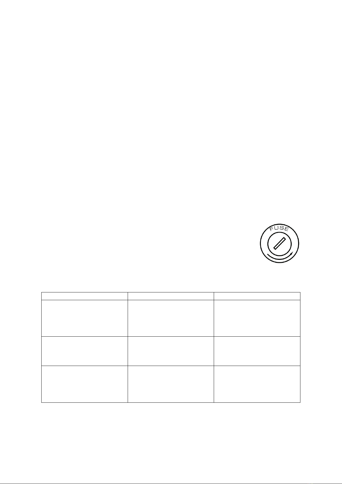
Fuse Replacement
1. Disconnect this product from the power outlet.
2. Using a screwdriver, unscrew the fuse holder cap from the housing.
3. Remove the blown fuse and replace with a good fuse of the same
type and rating (250V/T10A).
4. Screw the fuse holder cap back in place and reconnect power.
TROUBLESHOOTING
Problem
Possible Causes
Checks and Remedies
Fixture does not light up
-No mains supply
-Dimmer fader set to
0
-Faulty Lamp
-Check the power
supply voltage
-Increase value of the
dimmer channels
-Replace the Lamp
General low light intensity
-Dirty lens assembly
-Misaligned lens
assembly
-Clean the fixture
regularly
-Install lens assemble
properly
Fixture does not power up
-No power
-Loose of damaged
power cord
-Faulty internal power
supply
-Check for power on
power outlet
-Check power cord
-Replace internal
power supply
Contact an authorized service centre in case of technical problems, issues not reported in
the above table, or problems that cannot be resolved by the procedure given in the table.
This manual suits for next models
1
Table of contents
Other ShowPro Lighting Equipment manuals

ShowPro
ShowPro UniFog DMX User manual

ShowPro
ShowPro PLUTO 600 PROFILE User manual

ShowPro
ShowPro NITEC photon multi LEDNIT141 User manual

ShowPro
ShowPro Dreampix Driver 1800 IP User manual

ShowPro
ShowPro LED EPAR CW MULTI User manual

ShowPro
ShowPro K65 IP User manual

ShowPro
ShowPro X-Blinder User manual

ShowPro
ShowPro Venue Haze 1200 User manual

ShowPro
ShowPro ProShop LED PAR Hex-7 User manual

ShowPro
ShowPro Truss Mate II User manual


