Shure DFR11EQ Version 5 User manual

Model DFR11EQ Version 5
Quick Reference Guide
©2007 Shure Incorporated
27C8675 (Rev. 5)
Printed in U.S.A.
DFR11EQ Version 5
Digital Equalizer with Feedback Reducer, Limiter, and Delay
Egaliseur graphiquenumérique à réducteur de Larsen, écrêteur, et délai
Digitaler graphischer Equalizer mit Ruckkopplungsreduzier-Stufe, Limiter, und Delay
Ecualizadorgráfico digital con reductor de realimentación, limitador, y retardo
Equalizzatore frafico digitale con attenuatore di retroazione, limitatore, e ritardo
BYPASS
DFR FILTERS
SIGNAL
CLIP
SCE NES
123
HOLD TO
CLEAR
PRESS
TO LOCK
DFR FILTERS
DATA
POWER
DSP •20 BIT•48 KHz
DIGITAL EQ + FEEDBACK REDUCER
*27C8675*

2
TABLE OF CONTENTS
ENGLISH . . . . . . . . . . . . . . . . . . . . . . . . . . . . . . . . . . . . . . . . . . . . . . . . . . . . . . . . . . . . . . . . . . . . . . . . . . . . . . . . . 3
Installing the DFR11EQ Software . . . . . . . . . . . . . . . . . . . . . . . . . . . . . . . . . . . . . . . . . . . . . . . . . . . . . . . . . . . . . . . . . . . . . . . . . . . . . . . . . . 3
DFR11EQ Panels. . . . . . . . . . . . . . . . . . . . . . . . . . . . . . . . . . . . . . . . . . . . . . . . . . . . . . . . . . . . . . . . . . . . . . . . . . . . . . . . . . . . . . . . . . . . . . . 4
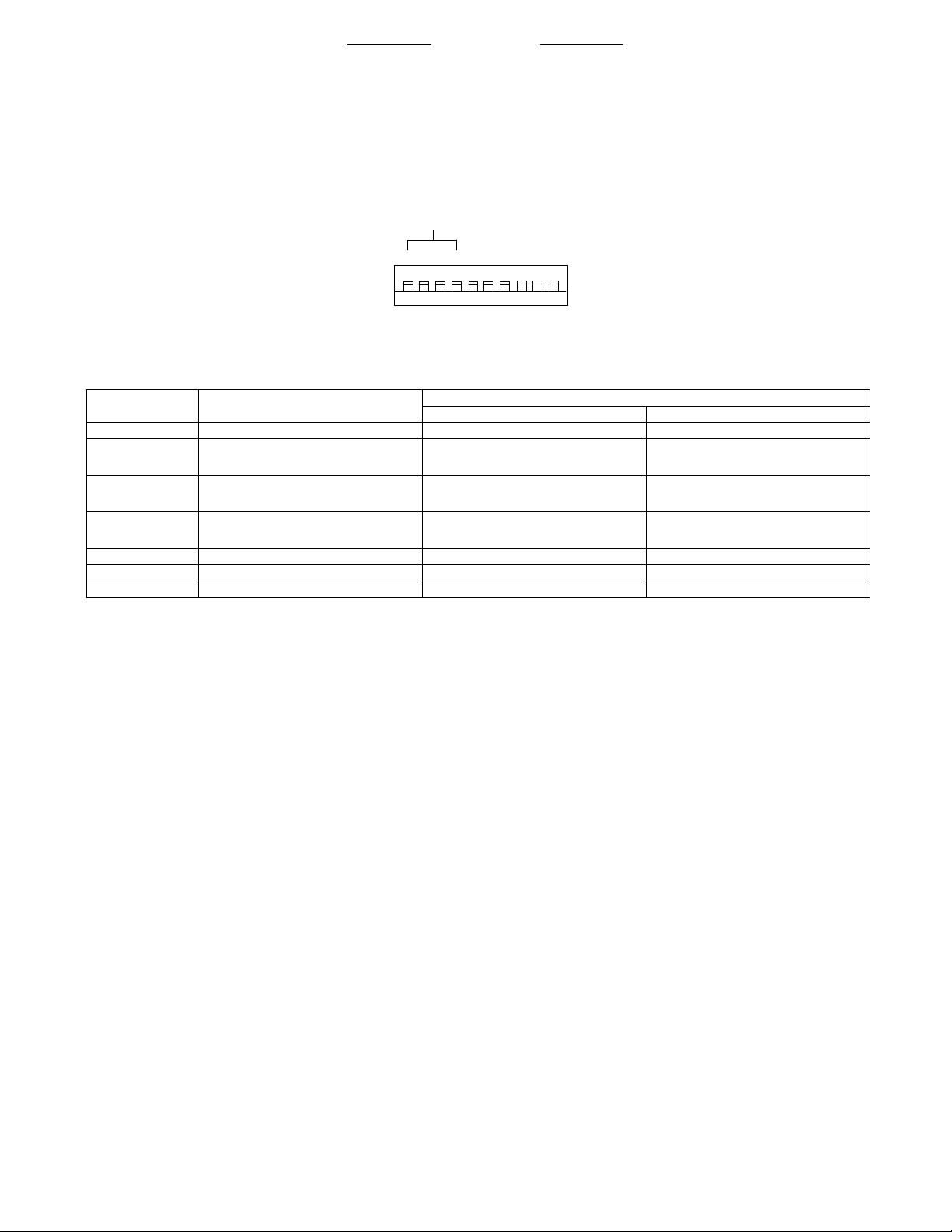
DIP Switches . . . . . . . . . . . . . . . . . . . . . . . . . . . . . . . . . . . . . . . . . . . . . . . . . . . . . . . . . . . . . . . . . . . . . . . . . . . . . . . . . . . . . . . . . . . . . . . . . . 5
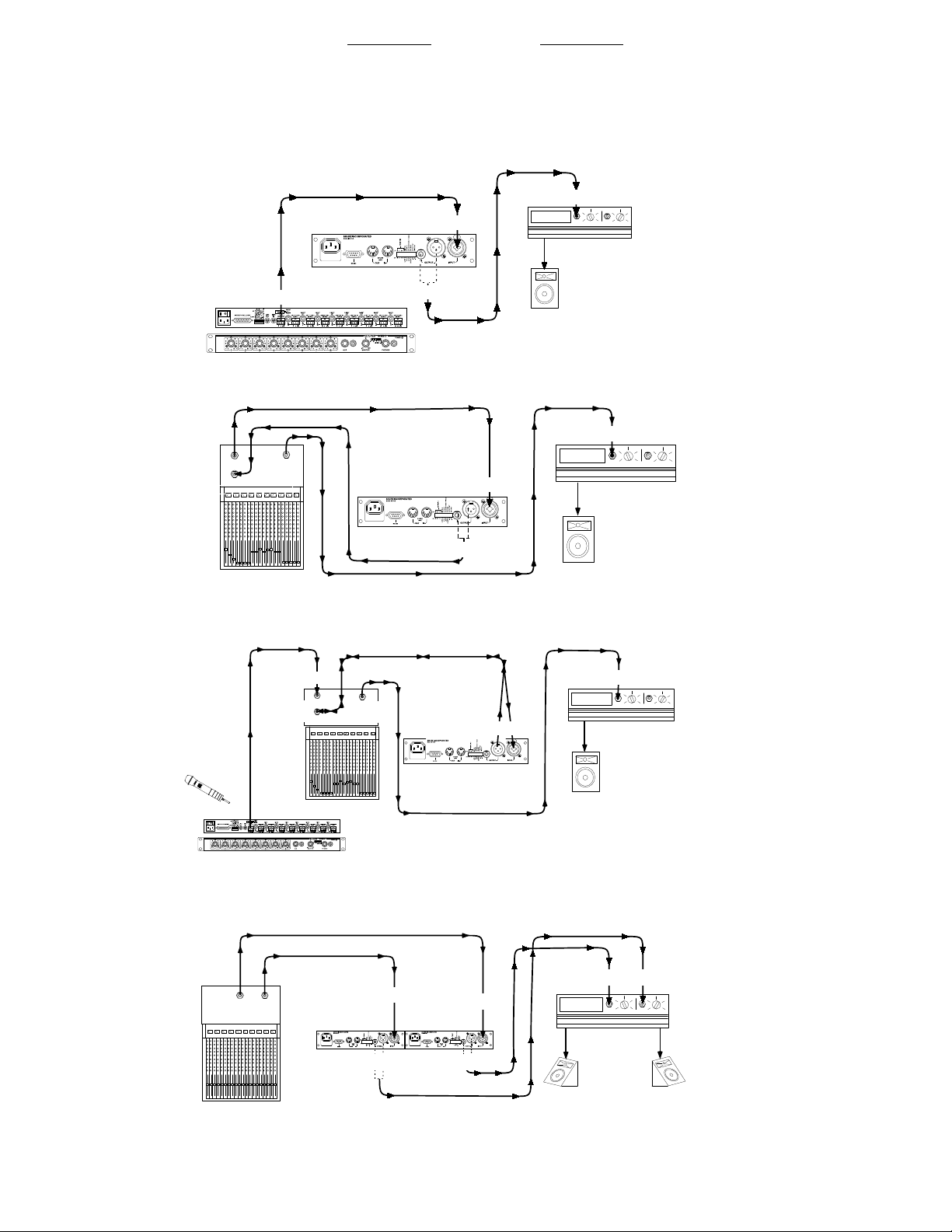
Audio Connections . . . . . . . . . . . . . . . . . . . . . . . . . . . . . . . . . . . . . . . . . . . . . . . . . . . . . . . . . . . . . . . . . . . . . . . . . . . . . . . . . . . . . . . . . . . . . . 6
Using the DFR11EQ as a Stand-alone Feedback Reducer. . . . . . . . . . . . . . . . . . . . . . . . . . . . . . . . . . . . . . . . . . . . . . . . . . . . . . . . . . . . . . . 7
Specifications . . . . . . . . . . . . . . . . . . . . . . . . . . . . . . . . . . . . . . . . . . . . . . . . . . . . . . . . . . . . . . . . . . . . . . . . . . . . . . . . . . . . . . . . . . . . . . . . . . 8
Audio Connectors. . . . . . . . . . . . . . . . . . . . . . . . . . . . . . . . . . . . . . . . . . . . . . . . . . . . . . . . . . . . . . . . . . . . . . . . . . . . . . . . . . . . . . . . . . . . . . . 9
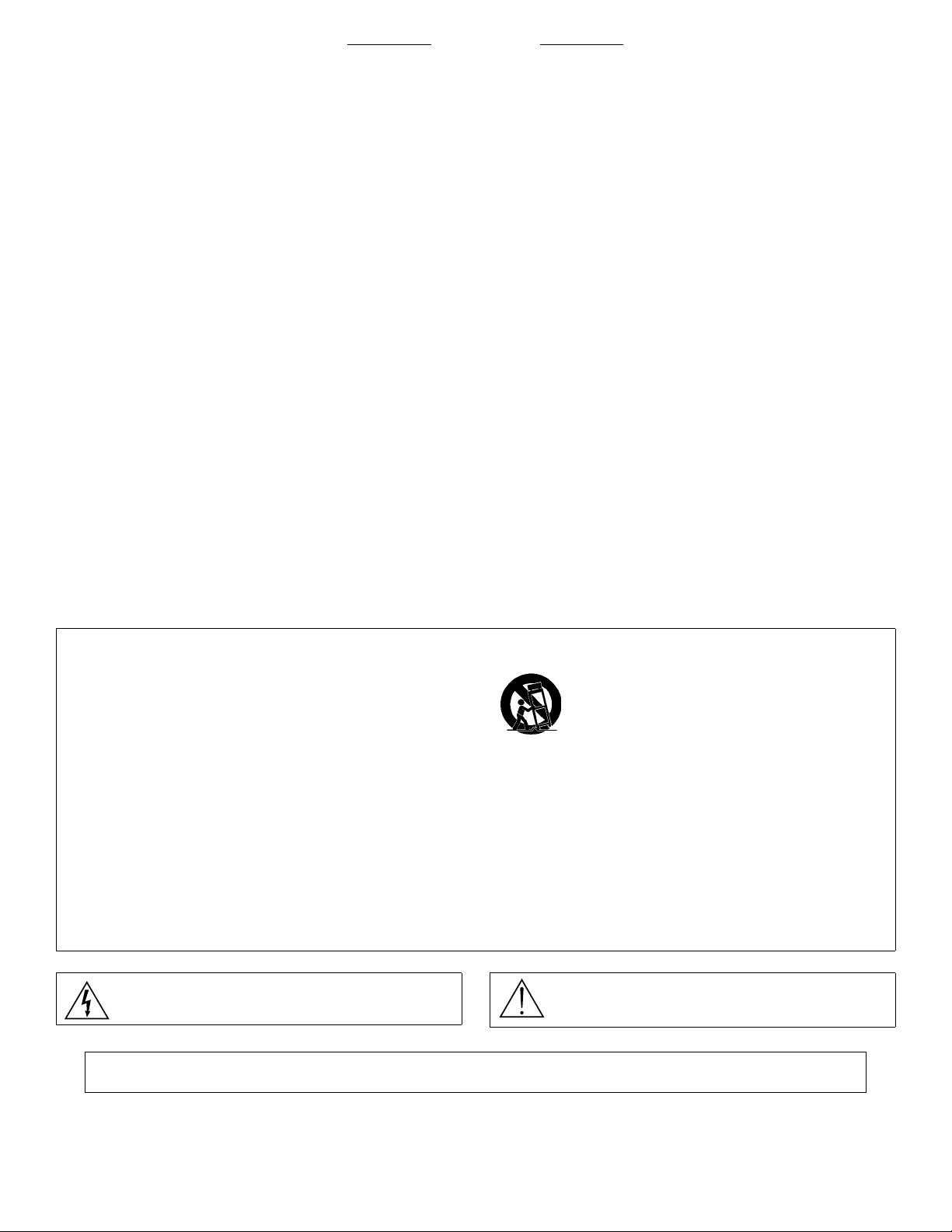
Certifications. . . . . . . . . . . . . . . . . . . . . . . . . . . . . . . . . . . . . . . . . . . . . . . . . . . . . . . . . . . . . . . . . . . . . . . . . . . . . . . . . . . . . . . . . . . . . . . . . . 10
Audio Cables . . . . . . . . . . . . . . . . . . . . . . . . . . . . . . . . . . . . . . . . . . . . . . . . . . . . . . . . . . . . . . . . . . . . . . . . . . . . . . . . . . . . . . . . . . . . . . . . . 11
Digital Connectors and Cables. . . . . . . . . . . . . . . . . . . . . . . . . . . . . . . . . . . . . . . . . . . . . . . . . . . . . . . . . . . . . . . . . . . . . . . . . . . . . . . . . . . . 12
FRANÇAIS. . . . . . . . . . . . . . . . . . . . . . . . . . . . . . . . . . . . . . . . . . . . . . . . . . . . . . . . . . . . . . . . . . . . . . . . . . . . . . . 13
Installation du logiciel. . . . . . . . . . . . . . . . . . . . . . . . . . . . . . . . . . . . . . . . . . . . . . . . . . . . . . . . . . . . . . . . . . . . . . . . . . . . . . . . . . . . . . . . . . . 13
Matériel DFR11EQ. . . . . . . . . . . . . . . . . . . . . . . . . . . . . . . . . . . . . . . . . . . . . . . . . . . . . . . . . . . . . . . . . . . . . . . . . . . . . . . . . . . . . . . . . . . . . 14
Interrupteur à positions multiples . . . . . . . . . . . . . . . . . . . . . . . . . . . . . . . . . . . . . . . . . . . . . . . . . . . . . . . . . . . . . . . . . . . . . . . . . . . . . . . . . . 15
Branchements audio . . . . . . . . . . . . . . . . . . . . . . . . . . . . . . . . . . . . . . . . . . . . . . . . . . . . . . . . . . . . . . . . . . . . . . . . . . . . . . . . . . . . . . . . . . . 16
Utilisation du DFR11EQ en tant que réducteur de larsen autonome . . . . . . . . . . . . . . . . . . . . . . . . . . . . . . . . . . . . . . . . . . . . . . . . . . . . . . . 17
Caractéristiques . . . . . . . . . . . . . . . . . . . . . . . . . . . . . . . . . . . . . . . . . . . . . . . . . . . . . . . . . . . . . . . . . . . . . . . . . . . . . . . . . . . . . . . . . . . . . . . 18
Connecteurs audio . . . . . . . . . . . . . . . . . . . . . . . . . . . . . . . . . . . . . . . . . . . . . . . . . . . . . . . . . . . . . . . . . . . . . . . . . . . . . . . . . . . . . . . . . . . . . 19
Homologations . . . . . . . . . . . . . . . . . . . . . . . . . . . . . . . . . . . . . . . . . . . . . . . . . . . . . . . . . . . . . . . . . . . . . . . . . . . . . . . . . . . . . . . . . . . . . . . . 20
Câbles audio . . . . . . . . . . . . . . . . . . . . . . . . . . . . . . . . . . . . . . . . . . . . . . . . . . . . . . . . . . . . . . . . . . . . . . . . . . . . . . . . . . . . . . . . . . . . . . . . . 21
Connecteurs et câbles numériques . . . . . . . . . . . . . . . . . . . . . . . . . . . . . . . . . . . . . . . . . . . . . . . . . . . . . . . . . . . . . . . . . . . . . . . . . . . . . . . . 22
DEUTSCH . . . . . . . . . . . . . . . . . . . . . . . . . . . . . . . . . . . . . . . . . . . . . . . . . . . . . . . . . . . . . . . . . . . . . . . . . . . . . . . 23
Installation der Software. . . . . . . . . . . . . . . . . . . . . . . . . . . . . . . . . . . . . . . . . . . . . . . . . . . . . . . . . . . . . . . . . . . . . . . . . . . . . . . . . . . . . . . . . 23
DFR11EQ Hardware . . . . . . . . . . . . . . . . . . . . . . . . . . . . . . . . . . . . . . . . . . . . . . . . . . . . . . . . . . . . . . . . . . . . . . . . . . . . . . . . . . . . . . . . . . . 24
Dip-Schalter . . . . . . . . . . . . . . . . . . . . . . . . . . . . . . . . . . . . . . . . . . . . . . . . . . . . . . . . . . . . . . . . . . . . . . . . . . . . . . . . . . . . . . . . . . . . . . . . . . 25
Audio-anschlüsse. . . . . . . . . . . . . . . . . . . . . . . . . . . . . . . . . . . . . . . . . . . . . . . . . . . . . . . . . . . . . . . . . . . . . . . . . . . . . . . . . . . . . . . . . . . . . . 26
Verwendung des DFR11EQ als Unabhängige Rückkopplungsreduzier-stufe . . . . . . . . . . . . . . . . . . . . . . . . . . . . . . . . . . . . . . . . . . . . . . . . 27
Technische Daten . . . . . . . . . . . . . . . . . . . . . . . . . . . . . . . . . . . . . . . . . . . . . . . . . . . . . . . . . . . . . . . . . . . . . . . . . . . . . . . . . . . . . . . . . . . . . 28
Audio-Steckverbindungen . . . . . . . . . . . . . . . . . . . . . . . . . . . . . . . . . . . . . . . . . . . . . . . . . . . . . . . . . . . . . . . . . . . . . . . . . . . . . . . . . . . . . . . 29
Zertifizierungen. . . . . . . . . . . . . . . . . . . . . . . . . . . . . . . . . . . . . . . . . . . . . . . . . . . . . . . . . . . . . . . . . . . . . . . . . . . . . . . . . . . . . . . . . . . . . . . . 30
Audio-Kabel . . . . . . . . . . . . . . . . . . . . . . . . . . . . . . . . . . . . . . . . . . . . . . . . . . . . . . . . . . . . . . . . . . . . . . . . . . . . . . . . . . . . . . . . . . . . . . . . . . 31
Digitale Steckverbinder und Kabel . . . . . . . . . . . . . . . . . . . . . . . . . . . . . . . . . . . . . . . . . . . . . . . . . . . . . . . . . . . . . . . . . . . . . . . . . . . . . . . . . 32
ESPAÑOL . . . . . . . . . . . . . . . . . . . . . . . . . . . . . . . . . . . . . . . . . . . . . . . . . . . . . . . . . . . . . . . . . . . . . . . . . . . . . . . 33
Instalacion del software . . . . . . . . . . . . . . . . . . . . . . . . . . . . . . . . . . . . . . . . . . . . . . . . . . . . . . . . . . . . . . . . . . . . . . . . . . . . . . . . . . . . . . . . . 33
Hardware del DFR11EQ . . . . . . . . . . . . . . . . . . . . . . . . . . . . . . . . . . . . . . . . . . . . . . . . . . . . . . . . . . . . . . . . . . . . . . . . . . . . . . . . . . . . . . . . 34
Interruptores dip. . . . . . . . . . . . . . . . . . . . . . . . . . . . . . . . . . . . . . . . . . . . . . . . . . . . . . . . . . . . . . . . . . . . . . . . . . . . . . . . . . . . . . . . . . . . . . . 35
Conexiones de audio . . . . . . . . . . . . . . . . . . . . . . . . . . . . . . . . . . . . . . . . . . . . . . . . . . . . . . . . . . . . . . . . . . . . . . . . . . . . . . . . . . . . . . . . . . . 36
Uso del DFR11EQ como reductor de realimentacion independiente. . . . . . . . . . . . . . . . . . . . . . . . . . . . . . . . . . . . . . . . . . . . . . . . . . . . . . . 37
Especificaciones. . . . . . . . . . . . . . . . . . . . . . . . . . . . . . . . . . . . . . . . . . . . . . . . . . . . . . . . . . . . . . . . . . . . . . . . . . . . . . . . . . . . . . . . . . . . . . . 38
Conectores de audio . . . . . . . . . . . . . . . . . . . . . . . . . . . . . . . . . . . . . . . . . . . . . . . . . . . . . . . . . . . . . . . . . . . . . . . . . . . . . . . . . . . . . . . . . . . 39
Certificaciones . . . . . . . . . . . . . . . . . . . . . . . . . . . . . . . . . . . . . . . . . . . . . . . . . . . . . . . . . . . . . . . . . . . . . . . . . . . . . . . . . . . . . . . . . . . . . . . . 40
Cables de audio . . . . . . . . . . . . . . . . . . . . . . . . . . . . . . . . . . . . . . . . . . . . . . . . . . . . . . . . . . . . . . . . . . . . . . . . . . . . . . . . . . . . . . . . . . . . . . . 41
Conectores y cables para señales digitales. . . . . . . . . . . . . . . . . . . . . . . . . . . . . . . . . . . . . . . . . . . . . . . . . . . . . . . . . . . . . . . . . . . . . . . . . . 42
ITALIANO. . . . . . . . . . . . . . . . . . . . . . . . . . . . . . . . . . . . . . . . . . . . . . . . . . . . . . . . . . . . . . . . . . . . . . . . . . . . . . . . 43
Installazione del software. . . . . . . . . . . . . . . . . . . . . . . . . . . . . . . . . . . . . . . . . . . . . . . . . . . . . . . . . . . . . . . . . . . . . . . . . . . . . . . . . . . . . . . . 43
Hardware del DFR11EQ . . . . . . . . . . . . . . . . . . . . . . . . . . . . . . . . . . . . . . . . . . . . . . . . . . . . . . . . . . . . . . . . . . . . . . . . . . . . . . . . . . . . . . . . 44
Interruttori dip. . . . . . . . . . . . . . . . . . . . . . . . . . . . . . . . . . . . . . . . . . . . . . . . . . . . . . . . . . . . . . . . . . . . . . . . . . . . . . . . . . . . . . . . . . . . . . . . . 45
Collegamenti audio. . . . . . . . . . . . . . . . . . . . . . . . . . . . . . . . . . . . . . . . . . . . . . . . . . . . . . . . . . . . . . . . . . . . . . . . . . . . . . . . . . . . . . . . . . . . . 46
Uso del DFR11EQ come attenuatore di retroazione autonomo. . . . . . . . . . . . . . . . . . . . . . . . . . . . . . . . . . . . . . . . . . . . . . . . . . . . . . . . . . . 47
Dati tecnici . . . . . . . . . . . . . . . . . . . . . . . . . . . . . . . . . . . . . . . . . . . . . . . . . . . . . . . . . . . . . . . . . . . . . . . . . . . . . . . . . . . . . . . . . . . . . . . . . . . 48
Connettori audio. . . . . . . . . . . . . . . . . . . . . . . . . . . . . . . . . . . . . . . . . . . . . . . . . . . . . . . . . . . . . . . . . . . . . . . . . . . . . . . . . . . . . . . . . . . . . . . 49
Omologazioni . . . . . . . . . . . . . . . . . . . . . . . . . . . . . . . . . . . . . . . . . . . . . . . . . . . . . . . . . . . . . . . . . . . . . . . . . . . . . . . . . . . . . . . . . . . . . . . . . 50
Cavi audio . . . . . . . . . . . . . . . . . . . . . . . . . . . . . . . . . . . . . . . . . . . . . . . . . . . . . . . . . . . . . . . . . . . . . . . . . . . . . . . . . . . . . . . . . . . . . . . . . . . 51
Connettori e cavi digitali . . . . . . . . . . . . . . . . . . . . . . . . . . . . . . . . . . . . . . . . . . . . . . . . . . . . . . . . . . . . . . . . . . . . . . . . . . . . . . . . . . . . . . . . . 52
日本語. . . . . . . . . . . . . . . . . . . . . . . . . . . . . . . . . . . . . . . . . . . . . . . . . . . . . . . . . . . . . . . . . . . . . . . . . . . . . . . . . . . 53
DFR11EQ のパネル . . . . . . . . . . . . . . . . . . . . . . . . . . . . . . . . . . . . . . . . . . . . . . . . . . . . . . . . . . . . . . . . . . . . . . . . . . . . . . . . . . . . . . . . . . . . 54
ディップ・スイッチ. . . . . . . . . . . . . . . . . . . . . . . . . . . . . . . . . . . . . . . . . . . . . . . . . . . . . . . . . . . . . . . . . . . . . . . . . . . . . . . . . . . . . . . . . . . . 55
オーディオ接続 . . . . . . . . . . . . . . . . . . . . . . . . . . . . . . . . . . . . . . . . . . . . . . . . . . . . . . . . . . . . . . . . . . . . . . . . . . . . . . . . . . . . . . . . . . . . . . . 56
DFR11EQ を単独でフィードバック・リデューサーとして使用する . . . . . . . . . . . . . . . . . . . . . . . . . . . . . . . . . . . . . . . . . . . . . . . . . . . . . . 57
仕様. . . . . . . . . . . . . . . . . . . . . . . . . . . . . . . . . . . . . . . . . . . . . . . . . . . . . . . . . . . . . . . . . . . . . . . . . . . . . . . . . . . . . . . . . . . . . . . . . . . . . . . . 58
オーディオ・コネクター . . . . . . . . . . . . . . . . . . . . . . . . . . . . . . . . . . . . . . . . . . . . . . . . . . . . . . . . . . . . . . . . . . . . . . . . . . . . . . . . . . . . . . . . 59
認定 . . . . . . . . . . . . . . . . . . . . . . . . . . . . . . . . . . . . . . . . . . . . . . . . . . . . . . . . . . . . . . . . . . . . . . . . . . . . . . . . . . . . . . . . . . . . . . . . . . . . . . . . 60
オーディオ・ケーブル . . . . . . . . . . . . . . . . . . . . . . . . . . . . . . . . . . . . . . . . . . . . . . . . . . . . . . . . . . . . . . . . . . . . . . . . . . . . . . . . . . . . . . . . . . 61
デジタル・コネクターとケーブル . . . . . . . . . . . . . . . . . . . . . . . . . . . . . . . . . . . . . . . . . . . . . . . . . . . . . . . . . . . . . . . . . . . . . . . . . . . . . . . . . 62

3
ENGLISH
DFR11EQ VERSION 5 QUICK REFERENCE GUIDE
The Shure DFR11EQ Version 5 offers the user a wide variety of digital sound processing capabilities. The DFR11EQ is most commonly controlled
through its software interface; however, the system can be used effectively as a stand-alone product.
This quick reference guide provides all necessary information for the installation of the operating software, as well as for use of the DFR11EQ
without the computer interface. Additional information on the advanced characteristics of the software is offered in the complete user guide included
on the furnished CD-Rom. The user guide can be used on line or printed. In addition, the system software includes searchable online help.
For information on the following topics, please see the full version of the DFR11EQ Version 5 user guide on the furnished CD-Rom.
• Characteristics of the hardware and the software
• Using the Shure Link system
• Full operation of the DFR11EQ Version 5 software
• Feedback reduction software
• Graphic and parametric equalizers
• Digital delay software
• Clipping reduction software
INSTALLING THE DFR11EQ SOFTWARE
MINIMUM COMPUTER REQUIREMENTS
The following are the minimum requirements to install and run the DFR11EQ Version 5 software.
• One 486DX 50 MHz IBM*-compatible computer (math
coprocessor required)
• 2 MB hard drive space
•4MBRAM
• CD-ROM drive
• Windows version 3.1x, 95, 98 or NT
• 1 available RS-232 serial (COM) port
• One RS-232 cable (9-pin to 9-pin)
CONNECTING THE DFR11EQ TO A COMPUTER VIA THE RS-232 (COM) PORT
1. Connect a 9-pin plug (male) of the cable to the RS-232 port of the
DFR11EQ. 2. Connect the other end of the cable to the RS-232 port of the com-
puter.
SOFTWARE INSTALLATION
1. Insert the supplied CD-ROM into the CD-ROM drive of your computer.
(After initial installation, the CD-ROM is not necessary to run the soft
ware.)
2. When the installation menu appears, click on DFR11EQ Software.
You will be led through the installation process. Note: if you are using
Windows 3.1X, go to File/Run and run d:\SETUP16.EXE.
3. Shure Setup will suggest a destination on your hard disk for the
DFR11EQ files and will check the computer hardware to ensure that a
coprocessor is present. It will also prompt you for your name and
organizational information.
NOTE: Remember to register your software by filling out and mailing the enclosed registration card, or online via the Shure World Wide
Web site ("http://www.shure.com"). This will ensure that you receive information about software updates with additional features as they
become available.
ACCESSING THE ONLINE USER GUIDE
1. Insert the CD-Rom in your computer’s CD-Rom drive. (Users of Win-
dows 3.1x: double-click on the "Setup 16" icon in the file of the CD-
Rom.)
2. An installation menu appears. Double-click on View User Guides, then
choose your preferred language.
3. The user guide is in PDF format. Acrobat Reader is necessary to view
PDF documents. Acrobat Reader is included on the CD-Rom, and
should be installed if necessary.
4. The full guide, or required sections of the guide, may be viewed online
or printed.
TO COMPUTER
RS-232 CONNECTOR
TO DFR11EQ RS-232
CONNECTOR (9-PIN MALE)

4
ENGLISH
DFR11EQ PANELS
FRONT PANEL
BYPASS DFR FILTERS Button and LED. Press this button to suspend feedback reducer operation and remove feedback filters from
the audio path. The bypass does not affect the equalizer, delay or limiter. When the LED illuminates, the feedback reducer is bypassed.
SIGNAL LED. Illuminates when input signal is present. Intensity varies with input signal level.
CLIP LED. Illuminates when the input signal is within 6 dB of clipping.
SCENE Selection Buttons and LEDs. Press one of these three buttons to select a pre-set scene. When a scene is selected, the cor-
responding LED will light.
LOCK/CLEAR Filters Button and LED. Press and release this button to lock the filters you have set. Hold down the button for three
seconds, and the filters will clear. The LED indicates that the filters are locked.
DFR FILTER LEDs (10). Indicate when individual feedback filters are active. When a filter changes or is added, the LED flashes, then
stays on.
DATA LED. Flashes in unison with the feedback filter LEDs when the detector is deploying a new feedback filter or changing an existing
one, and also blinks whenever the unit is communicating with a connected computer.
POWER LED. LED illuminates when unit is attached to a power supply.
BACK PANEL
Power Connector with Integral Fuse. Connects to AC power. The fuse is located in the drawer below the connector.
9-Pin RS-232 Port. Connects the unit to a computer. For use with DFR11EQ software and for DSP firmware upgrades. (Compatible with
AMX and Crestron systems.
Shure Link Interface. Allows linking of up to 16 Shure Link devices (DFR11EQs, DP11EQs, and UA888s), which may be accessed by
computer.
DIP Switches. Switches 1 through 4 are used to select the device ID. Switches 5 through 10 change other available options. See DIP
Switches.
Separate ¼” and XLR audio output jacks.
Combined ¼” and XLR audio output jacks.

5
ENGLISH
DIP SWITCHES
There are ten DIP Switches located on the back of the DFR11EQ. The following table describes the function of each switch. See the DFR11EQ
User’s Guide on the Software CD ROM for instructions on how to set the Device ID.
*NOTE: See the Set Up instructions in the Using the DFR11EQ as a Stand-Alone Feedback Reducer section of this Quick Reference
Guide for instructions and warnings regarding use of the Input and Output Sensitivity DIP switches.
HOLD/UPDATE
UPDATE position... When the HOLD/UPDATE DIP switch is in the UPDATE position (default), the DFR11EQ saves the feedback filters every
time the unit is powered off. When the DFR11EQ is powered on again, the feedback filters will be at exactly the same settings as when the unit was
powered down.
HOLD position... When the HOLD/UPDATE DIP switch is changed to the HOLD position, the DFR11EQ immediately saves the feedback filters
at the current settings. When the DFR11EQ is powered off, any changes made to the feedback filters after the switch was set will be forgotten. When
powered on again, the feedback filter settings will be exactly the same as when the HOLD/UPDATE DIP switch was changed to the HOLD position.
This feature is useful for storing the best filter settings for a sound system.
To store filter settings in the HOLD memory:
1. Set the Hold/Update DIP switch to the Update position;
2. Ring out the room until all fixed filters are set;
3. Set the Hold/Update DIP switch to the Hold position;
4. During the performance, the DFR11EQ will change dynamic filters and deepen fixed ones;
5. After the performance, turn the power off and back on; the DFR filters are restored to the state they were in before the performance.
DIP SWITCH FUNCTION POSITION
UP DOWN
1-4 Shure Link Device ID (see CD-Rom user guide)
5 Feedback Filter Bandwidth Select
Determines the Q of the feedback filter. High Q
1/10–octave Feedback Filters remain narrow as
they deepen
Low Q
1/10–octave Feedback Filters widen as they
deepen
6 Feedback Filter Memory Mode Update
Stores changed feedback filter settings on
power down
Hold
Discards changed feedback filter settings on
power down, but holds original settings
7 Front Panel Lockout Unlock Front Panel
Front panel buttons operational Lock
Front panel buttons inactive (except the power
switch).
8 unused - -
9* Output Sensitivity +4 dBu Output –10 dBV Output
10* Input Sensitivity +4 dBu Input –10 dBV Input
UP 1
1
2
2
3
3
4
4
HIGH QLOW Q
UPDATEHOLD
LOCK UNLOCK FRONT PANEL
UNUSED UNUSED
-10 +4 OUTPUT
-10 +4 INPUT
DN
DEVICE ID

6
ENGLISH
AUDIO CONNECTIONS
NOTE: All cables must be shielded.
Between the Mixer Main Output and the Power Amplifier The DFR11EQ is most commonly placed between the main output of a mixer and the
input of a power amplifier. At the main output, the unit will affect all input channels. This setup is ideal for using the DFR11EQ as a feedback reducer
and as an equalizer.
At a Subgroup Insert When using a multiple bus mixer, the DFR11EQ can be connected to a single subgroup insert. The unit will affect only the
channels associated with that subgroup: the other channels will remain unaffected.
Inserted in an Input Channel If only a single microphone is creating feedback problems, the DFR11EQ can be inserted on that channel alone.
This is especially useful for wireless microphones, because the constant movement of a performer may bring the microphone too close to the sound
reinforcement loudspeakers.
Inserted Between Mixer and Monitor Since monitor loudspeakers and microphones are usually in close proximity, the DFR11EQ can be con-
nected to stabilize a monitor system. Place a DFR11EQ on the monitor output which goes to the monitor loudspeaker. For multiple monitor mixes, a
DFR11EQ should be placed at the output of each monitor send.
DFR11EQ
LINE OUT
MIXER
LOUDSPEAKER
LINE IN
POWER AMPLIFIER
LINE OUT
LINE IN
Ñ
Ñ
Ñ
Ñ
Ñ
Ñ
Ñ
Ñ
Ñ
DFR11EQ
LINE OUT
MIXER LOUDSPEAKER
LINE IN
POWER AMPLIFIER
SUB RETURN LINE IN
SUB SEND LINE
OUT
MAIN
Ñ
Ñ
DFR11EQ
LINE OUT
MIXER LOUDSPEAKER
LINE IN
POWER AMPLIFIER
CHANNEL 1 IN
LINE IN
CHANNEL 1
INSERT
LINE OUT
WIRELESS RECEIVER
LINE OUT
MAIN
DFR11EQ
Ñ
Ñ
ÑÑ
Ñ
Ñ
Ñ
Ñ
Ñ
Ñ
Ñ
Ñ
Ñ
Ñ
DFR11EQ
MIXER
MONITOR
LOUDSPEAKER
LINE IN
MONITOR
POWER AMPLIFIER
LINE OUT LINE OUT
LINE IN
AUX 1
OUT AUX 2
OUT
LINE IN LINE IN

7
ENGLISH
USING THE DFR11EQ AS A STAND-ALONE FEEDBACK REDUCER
SETUP FOR FEEDBACK CONTROL
There are two basic ways in which to set–up the DFR11EQ as a stand–alone feedback reducer: The “Ring Out” method and the “Insurance Policy”
method. Each is valid for different situations.
The “Ring Out” method is a preemptive measure in which the system gain is raised beyond the normal setting to deliberately make the system
feed back. The DFR11EQ will then set its filters, and the system gain is then reduced slightly, and the system is stable and usable. This set–up method
is primarily used for systems which are operated near the feedback point and need an extra margin of stability.
For the “Insurance Policy” method, the DFR11EQ is simply installed in the sound system, but filters are not set prior to use. The DFR11EQ adds
extra insurance against feedback: the system is not expected to feedback, but if it does, the DFR11EQ is there to catch it. This set–up method is used
for systems which already have sufficient gain–before–feedback, but need protection from the occasional stray feedback which can occur due to non–
stationary microphones or user–adjustable gain controls.
SETUP
1. Connect the DFR11EQ in the desired signal path location. See Audio
Connections. 2. Set the input and output level DIP switches to the appropriate settings
for the sensitivities of the connected equipment.
3. Set the system gain to minimum, and power up all of the equipment.
4. Slowly raise the gain of the system, and set the gain of each micro-
phone to achieve the desired level.
5. The red CLIP LED should illuminate only on the highest signal peaks.
If it illuminates more frequently, check to see that the input level
switch is set properly. If it is, lower the level of the signal going into the
DFR11EQ.
6. At this point it is highly recommended to equalize the sound system
with the DFR11EQ’s built-in equalizer (see Computer Interface) or an
external equalizer. The DFR11EQ’s feedback reducer is more effec-
tive on a well-equalized sound system.
RINGING OUT THE SYSTEM (“RING OUT” METHOD ONLY)
1. If necessary, clear any notch filters in the DFR11EQ by pressing the
CLEAR button. Turn off the BYPASS and LOCK LEDs if they are not
already off.
2. Slowly raise the gain of the signal going through the DFR11EQ. When
feedback occurs, the DFR11EQ will insert a filter deep enough to stop
the feedback.
3. Repeat step 2 until all fixed filters are set. (There are 5 fixed filters,
unless changed by the user via the computer interface.)
4. Lower the gain by 3 to 6 dB to stabilize the sound system.
NOTE: If you are using an auto mixer, lock on all inputs during ring-out phase.
SCENE SELECTION
There are three SCENE SELECTION buttons and LEDs on the front panel of the DFR11EQ. These allow easy access of scenes (preset EQ, DFR
filter and delay settings) without a computer. This allows access to scenes created using the DFR11EQ Version 5 software after disconnecting the
computer from the DFR11EQ. Alternatively, DFR–only scenes may be created without a computer as follows:
1. Select scene one, two or three on the front panel.
2. Ring out the system (see Ringing Out the System). The filters created during the ringing out phase will now be recalled whenever the
selected scene is chosen.
NOTE: The three Scene buttons on the front panel are factory preset to provide a flat response until specific scenes are created by the
user.
WARNING: Other equipment may potentially be damaged after the DFR11EQ is powered off if the
DFR11EQ input is set to +4 and the output is set to -10. It is recommended that you avoid using this setting.
SCENES
1
2
3

8
ENGLISH
SPECIFICATIONS
Frequency Response
20 to 20k Hz ±1.0 dB re 1 kHz
Dynamic Range
104 dB minimum, A-weighted, 20 Hz to 20 kHz
Sampling Rate
48 kHz
Digital–to–Analog, Analog–to–Digital Conversion
20 bit resolution
Voltage Gain
–1 dB ±1dB (power off)
0 dB ±2 dB (equal input and output sensitivities)
12 dB ±2 dB (input –10 dBV, output +4 dBu)
–12 dB ±2 dB (input +4 dBu, output –10 dBv)
Impedance
Input: 47 kΩ±20% actual
Output: 120 Ω±20% actual
Input Clipping Level
+18 dBu minimum (at +4 dBu setting)
+6 dBu minimum (at –10 dBV setting)
Output Clipping Level
+18 dBu minimum (at +4 dBu setting)
+6 dBu minimum (at –10 dBV setting)
Total Harmonic Distortion
< 0.05% at 1 kHz, +4 dBu, 20 to 20 kHz
LED Signal Indicators
Clip: 6 dB down from input clipping
Propagation Delay from Input to Output
< 1.0 ms, all filters set to Flat (0 ms delay setting)
Polarity
Input to output: non-inverting
XLR: pin 2 positive with respect to pin 3
1/4in. TRS: tip positive with respect to ring
Operating Voltage
DFR11EQ: 120 Vac, 50/60 Hz, 75 mA max
DFR11EQJ: 100 Vac, 50/60 Hz, 75 mA max
DFR11EQE: 230-240 Vac, 50/60 Hz, 38 mA max
Temperature Range
Operating: –7° to 49° C (20° to 140° F)
Dimensions
219 mm x 137 mm x 44.5 mm (8 5/8in x 5 3/8in x 1 3/4in)
Weight
930 g (2.05 lbs)
Fuse
DFR11EQ:120 Vac. Fuse: 100 mA, 250V time delay
DFR11EQJ: 100 Vac.Fuse: 100 mA, 250V time delay
DFR11EQE: 230-240 Vac. Fuse: 50 mA, 250 V time delay
In order to change a blown fuse, remove the power cord and pry open
the drawer with a flathead screwdriver.
FEEDBACK FILTERS
Ten (10) 1/10 octave adaptive notch filters from 60 Hz to 20 kHz
Deployed to 1 Hz resolution of feedback frequency
Deployed in depths of 3 dB, 6 dB, 9 dB, 12 dB, and 18 dB (12.5
Low Q in graphic EQ mode) attenuation
Filter shape variable between HI Q and LOW Q (see High Q vs.
Low Q Filters).
GRAPHIC EQUALIZER
Frequency Bands
30 bands on ISO, 1/3octave centers
Filter Type
1/3octave, constant Q
Maximum Boost
6 dB per band
Maximum Cut
12dB per band, high- and low-pass filters, 12dB/octave nominal
PARAMETRIC EQUALIZER
Frequency Bands
10 bands, variable frequency, variable Q
Boost/Cut Range
+6 dB to –18 dB per band
Q Range
1/40 octave to 2 octave
Shelf/Rolloff Filters
Shelf, +6 to –18 dB per filter
Rolloff, 6dB, 12dB, 18dB, or 24dB per octave nominal
DELAY
Up to 1300 ms
LIMITER
Threshold: –60 dBFs to –0.5 dBFs, 0.5 dB resolution
Attack: 1 ms to 200 ms
Decay: 50 ms to 1000 ms
Ratio: ∞ to 1
FUSE

9
ENGLISH
AUDIO CONNECTORS
DFR11EQ AUDIO INPUT DFR11EQ AUDIO OUTPUT
FURNISHED ACCESSORIES
Power Cable (DFR11EQ/DFR11EQJ)*............. 95A8389
Power Cable (DFR11EQE)* ............................. 95A8247
Power Cable Clamp.........................................*95A8712
5 pin DIN Shure Link Cable.............................. 95A8676
Single Mount Rack Bracket.............................. 53A8484
Dual Mount Rack Bracket................................. 53B8484
Straddle Bars.................................................... 53A8443
DFR11EQ Version 5
Software/User’s Guide CD-ROM....................95A8830A
*NOTE: The power cord and power cable clamp is supplied assembled. If a replacement power cord is needed, a power cord clamp is also
required. If not assembled, the power cord clamp should be clamped as close to the female end of the power cord as possible.
RACK MOUNTING
SINGLE UNIT
DUAL–MOUNTED UNITS
Connector:
(XLR and 1/4 inch
combined)
XLR (female) 1/4 inch
phone plug
(female)
Configuration: active balanced active balanced
Actual
Impedance: 47 kΩ47 kΩ
Nominal
Input Level: +4 dBu
(+4 input level)
–10 dBV
(–10 input level)
+4 dBu
(+4 input level)
–10 dBV
(–10 input level)
Maximum
Input Level: +18 dBu
(+4 input level)
+6 dBV
(–10 input level)
+18 dBu
(+4 input level)
+6 dBV
(–10 input level)
Pin
Assignments: Pin 1 = ground
Pin 2 = hot
Pin 3 = cold
Tip = hot
ring = cold
sleeve = ground
Voltage /
Current/
Phantom Power
Protection?
yes yes
Connector:
(XLR and 1/4 inch
separate)
XLR (male) 1/4 inch
phone plug
(female)
Configuration: active balanced
cross coupled active balanced
cross coupled
Actual
Impedance: 120 Ω120 Ω
Nominal
Output Level: +4 dBu
(+4 output level)
–10 dBV
(–10 output level)
+4 dBu
(+4 output level)
–10 dBV
(–10 output level)
Maximum
Output Level: +18 dBu
(+4 output level)
+6 dBV
(–10 output level)
+18 dBu
(+4 output level)
+6 dBV
(–10 output level)
Pin
Assignments: Pin 1 = ground
Pin 2 = hot
Pin 3 = cold
Tip = hot
ring = cold
sleeve = ground
Voltage /
Current/
Phantom Power
Protection?
yes yes
Ñ
ÑÑ ÑÑÑÑ
Ñ
Ñ
Ñ
Ñ
Ñ
Ñ
Ñ
Ñ
Ñ
Ñ
ÑÑÑ
ÑÑÑ
ÑÑÑÑ
ÑÑÑÑÑ
Ñ
ÑÑÑ
Ñ
ÑÑÑ
ÑÑ
ÑÑ
Ñ
ÑÑÑ
Ñ
Ñ
ÑÑ
ÑÑ
ÑÑ
Ñ
ÑÑ
ÑÑÑ
Ñ
ÑÑ
ÑÑÑ
Ñ
ÑÑÑ
Ñ
Ñ
ÑÑ
ÑÑ
ÑÑ
ÑÑ
ÑÑ
Ñ
Ñ
Ñ
ÑÑÑ
ÑÑ
ÑÑ
Ñ
ÑÑÑ
Ñ
ÑÑ
ÑÑ
ÑÑ
ÑÑÑÑÑ
Ñ
ÑÑÑÑ
Ñ
Ñ
ÑÑ
ÑÑ

10
ENGLISH
CERTIFICATIONS
DFR11EQ (VERSION 5)
UL Listed and cUL Listed to UL 6500 and CSA E65. Approved under the Verification provision of FCC part 15 as a Class B Digital Device.
DFR11EQE (VERSION 5)
Eligible to bear CE marking. Conforms to European Union Low Voltage Directive 2006/95/EC; VDE GS-Certified to EN 60065.
Conforms to European EMC Directive 89/336/EEC. Meets applicable tests and performance criteria in European Standard EN55103 (1996) Parts
1 and 2, for residential (E1) and light industrial (E2) environments.
NOTE:
*EMC conformance testing is based on the use of supplied and recommended cable types. The use of other cable types may degrade
EMC performance.
*Under extremely abnormal conditions of electrical fast transients on the power line, communication may be interrupted between the
DFR11EQ and the controlling PC. The unit will not be damaged; normal operation will resume after the CONNECT button or command is
used to restore the connection
*This Class B digital apparatus complies with Canadian ICES-003
INFORMATION TO USER
Changes or modifications not expressly approved by Shure Incorporated could void your authority to operate this equipment.
This equipment has been tested and found to comply with the limits for a Class B digital device, pursuant to Part 15 of the FCC Rules. These limits
are designed to provide reasonable protection against harmful interference in a residential installation. This equipment generates, uses and can radi-
ate radio frequency energy and, if not installed and used in accordance with the instructions, may cause harmful interference to radio communications.
However, there is no guarantee that interference will not occur in a particular installation. If this equipment does cause harmful interference to radio
or television reception, which can be determined by turning the equipment off and on, the user is encouraged to try to correct the interference by one
or more of the following measures:
• Reorient or relocate the receiving antenna.
• Increase the separation between the equipment and receiver.
• Connect the equipment into an outlet on a circuit different from that to which the receiver is connected.
• Consult the dealer or an experienced radio/TV technician for help
! IMPORTANT SAFETY INSTRUCTIONS !
1. READ these instructions.
2. KEEP these instructions.
3. HEED all warnings.
4. FOLLOW all instructions.
5. DO NOT use this apparatus near water.
6. CLEAN ONLY with dry cloth.
7. DO NOT block any ventilation openings. Install in accordance with the manu-
facturer's instructions.
8. DO NOT install near any heat sources such as radiators, heat registers, stoves,
or other apparatus (including amplifiers) that produce heat.
9. DO NOT defeat the safety purpose of the polarized or grounding-type plug. A
polarized plug has two blades with one wider than the other. A grounding type
plug has two blades and a third grounding prong. The wider blade or the third
prong are provided for your safety. If the provided plug does not fit into your out-
let, consult an electrician for replacement of the obsolete outlet.
10. PROTECT the power cord from being walked on or pinched, particularly at plugs,
convenience receptacles, and the point where they exit from the apparatus.
11. ONLY USE attachments/accessories specified by the manufacturer.
12.
13. UNPLUG this apparatus during lightning storms or when unused for long periods of
time.
14. REFER all servicing to qualified service personnel. Servicing is required when the
apparatus has been damaged in any way, such as power-supply cord or plug is dam-
aged, liquid has been spilled or objects have fallen into the apparatus, the apparatus
has been exposed to rain or moisture, does not operate normally, or has been
dropped.
15. DO NOT expose the apparatus to dripping and splashing. DO NOT put objects filled
with liquids, such as vases, on the apparatus.
16. The MAINS plug or an appliance coupler shall remain readily operable.
17. The airborne noise of the apparatus does not exceed 70dB (A).
18. Apparatus with CLASS I construction shall be connected to a MAINS socket outlet
with a protective earthing connection.
19. To reduce the risk of fire or electric shock, do not expose this apparatus to rain or
moisture.
20. Do not attempt to modify this product. Doing so could result in personal injury
and/or product failure.
USE only with acart, stand, tripod, bracket,or table
specified by the manufacturer, or sold with the
apparatus. When a cart is used, use caution when
moving the cart/apparatus combination to avoid
injury from tip-over.
This symbol indicates that dangerous voltage constituting a
risk of electric shock is present within this unit.
This symbol indicates that there are important operating and
maintenance instructions in the literature accompanying this unit.
WARNING:
Voltages in this equipment are hazardous to life. No user-serviceable parts inside. Refer all servicing to qualified service personnel. The
safety certifications do not apply when the operating voltage is changed from the factory setting.

11
ENGLISH
AUDIO CABLES
The variety of connectors on audio equipment sometimes leads to confusion in cabling. The diagrams below provide cabling recommendations for
most common cabling situations. The following is not a complete list, only a sample of some of the more commonly used cables and applications.
Some of the equipment in a given sound system may have different pinouts than the given examples. Consult the documentation for that equipment.
NOTE: All audio cables must be shielded. Except for the Shure Link cable, none of the cables shown is supplied with the DFR11EQ
Version 5.
• Mixer Line Out to DFR11EQ Input
• DFR11EQ Output to Amplifier Input
• DFR11EQ Output to Mixer Sub Return
• Mixer Send to DFR11EQ Input
• Mixer Sub Send to DFR11EQ Input
XLR (MALE) TO XLR (FEMALE) ¼ IN. TO ¼ IN. BALANCED
¼ IN. TO ¼ IN. UNBALANCED ¼ IN. BALANCED TO ¼ IN. UNBALANCED
XLR (MALE) TO ¼ IN. BALANCED XLR (FEMALE) TO ¼ IN. BALANCED
XLR (FEMALE) TO ¼ IN. UNBALANCED RCA TO ¼ IN. UNBALANCED
• DFR11EQ output to amplifier input
Y-ADAPTER CABLE, ¼ IN. BALANCED TO ¼ IN. UNBALANCED
• Mixer send/return (insert) to DFR11EQ input and output
PIN 2 + PIN 1
PIN 3 -
PIN 3 -
PIN 1 PIN 2 +
SLEEVE
SLEEVE RING -
TIP +
RING -
TIP +
SLEEVE
TIP +
SLEEVE
TIP +
SLEEVE
SLEEVE RING -
TIP +
TIP +
SLEEVE RING -
TIP +
PIN 3 -
PIN 2 + PIN 1
SLEEVE RING -
TIP +
PIN 3 -
PIN 2 +
PIN 1
SLEEVE
TIP +
PIN 3 -
PIN 2 +
PIN 1
SLEEVE
TIP + SLEEVE
TIP +
SLEEVE
TIP +
RING -

12
ENGLISH
DIGITAL CONNECTORS AND CABLES
BRETELLE ¼ PO SYMÉTRIQUE À ¼ PO ASYMÉTRIQUE
NOTE: All digital connectors and cables must be shielded.
COMPUTER INTERFACE: 9-PIN TO 9-PIN RS-232 CABLE
SHURE LINK CABLE: 5-PIN DIN CABLE (MIDI-COMPATIBLE CABLE)
54321
9
8
7
6
9
8
7
6
5
4
3
2
1
9
8
7
6
5
4
3
2
1
9
8
7
6
5
4
3
2
1
FUNCTION PIN #
-1
RX 2
TX 3
DTR 4
GND 5
DSR 6
RTS 7
CTS 8
-9
9-PIN FEMALE
TO COMPUTER
9-PIN MALE
TO DFR11EQ
COMPUTER 9-PIN RS-232
MALE CONNECTOR
DFR11EQ RS-232
FEMALE CONNECTOR
3
5
2
4
1
3
5
2
4
1
3
5
2
4
1
3
5
2
4
1
FUNCTION PIN #
-1
DATA 4
SHIELD 2
DATA 5
-3
SHURE LINK OUT
SHURE LINK IN

www.shure.com
United States:
Shure Incorporated
5800 West Touhy Avenue
Niles, IL 60714-4608 USA
Phone: 847-600-2000
Fax: 847-600-1212
Email: [email protected]
©2007 Shure Incorporated
Europe, Middle East, Africa:
Shure Europe GmbH
Wannenäckestr. 28,
74078 Heilbronn, Germany
Phone: 49-7131-72140
Fax: 49-7131-721414
Email: [email protected]
Asia, Pacific:
Shure Asia Limited
Unit 301, 3rd Floor
Citicorp Centre
18, Whitfield Road
Causeway Bay, Hong Kong
Phone: 852-2893-4290
Fax: 852-2893-4055
Email: [email protected]
Canada, Latin America,
Caribbean:
Shure Incorporated
5800 West Touhy Avenue
Niles, IL 60714-4608 USA
Phone: 847-600-2000
Fax: 847-600-6446
Email: [email protected]
Other manuals for DFR11EQ Version 5
5
Table of contents
Other Shure Recording Equipment manuals

Shure
Shure PSM 900 User manual

Shure
Shure M97xE User manual

Shure
Shure P3RA User manual

Shure
Shure ANIUSB-Matrix User manual

Shure
Shure AMS880 User manual

Shure
Shure PSM 600 User manual

Shure
Shure ANIUSB-Matrix User manual

Shure
Shure ANI22 User manual

Shure
Shure ANI22 User manual

Shure
Shure PSM 900 Programming manual