Shuttle MB47N User manual

MB47N
Pentium 4/Celeron, 478-Pin Processor
Based MAIN BOARD
User's Manual

Shuttle®
MB47N
Pentium 4/Celeron,478-pin processor based Mainboard
Manual Version 1.1
Copyright
Copyright©
2002 by Shuttle®
Inc. All Rights Reserved.
No part of this publication may be reproduced, transcribed, stored in a retrieval system,
translated into any language, or transmitted in any form or by any means, electronic,
mechanical, magnetic, optical, chemical, photocopying, manual, or other ise, ithout
prior ritten permission from Shuttle®
Inc.
isclaimer
Shuttle®
Inc. shall not be liable for any incidental or consequential damages resulting
from the performance or use of this product.
This company makes no representations or arranties regarding the contents of this
manual. Information in this manual has been carefully checked for reliability; ho ever,
no guarantee is given as to the correctness of the contents. In the interest of continued
product improvement, this company reserves the right to revise the manual or include
changes in the specifications of the product described ithin it at any time ithout notice
and ithout obligation to notify any person of such revision or changes. The information
contained in this manual is provided for general use by the customers.
Trademarks
Shuttle is a registered trademark of Shuttle Inc.
Intel, Pentium is a registered trademarks of Intel Corporation.
PS/2 is a registered trademark of IBM Corporation.
AWARD is a registered trademark of A ard Soft are Inc.
Microsoft and Windo s are registered trademarks of Microsoft Corporation.
General Notice: Other brand and product names used herein are for identification
purposes only and may be trademarks of their respective o ners.
M584

- 1 -
1 INTRODUCTION ................................................................................. 4
1.1 ITEM CHECKLIST ........................................................................................4
2 FEATURES.......................................................................................... 5
2.1 SPECIFICATIONS ........................................................................................5
3 HARDWARE INSTALLATION ............................................................. 8
3.1 STEP BY STEP INSTALLATION.................................................................. 8
Accessories of MB47N ............................................................................ 8
STEP 1 Install the CPU ............................................................................. 9
STEP 2 Set umpers .............................................................................. 11
STEP 3 Install DDR SDRAM System Memory ........................................ 11
STEP 4 Install Peripherals in System Case ............................................ 12
STEP 5 Mount the Mainboard on the Computer Chassis ....................... 13
STEP 6 Connect Front Panel Switches/LEDs/Speaker/USB/AUDIO1 ... 14
STEP 7 Connect IDE and Floppy Disk Drives ......................................... 16
STEP 8 Connect Other Internal Peripherals ........................................... 16
STEP 9 Connect the Power Supply ........................................................ 17
STEP 10 Install Add-on Cards in Expansion Slots .................................. 17
STEP 11 Connect External Peripherals to Back Panel ........................... 18
STEP 12 Install Drivers & Software Components ................................... 19
3.2 JUMPER SETTINGS .................................................................................. 20
UMPERS & CONNECTORS GUIDE .................................................... 21
Jumpers
Clear CMOS Setting ( P1) .................................................................... 24
BIOS Flash Protecion Setting ( P3)............................................................... 24
LAN Select on Board Setting( P4) ................................................................ 25
Core Voltage Select umper Setting(VID4~VID0)........................................ 25
TABLE OF CONTENTS

- 2 -
Back-Panel Connectors
PS/2 Keyboard & PS/2 Mouse Connectors ............................................ 27
LAN Port Connector ............................................................................... 27
USB0/USB1 Port Connectors .................................................................27
COM Port Connector .............................................................................. 27
VGA Port Connector ....................................................................................... 28
Parallel Port Connector...........................................................................28
Line-Out Port Connector ......................................................................... 28
Line-In Port Connector ............................................................................ 28
Mic-In Port Connector ............................................................................. 28
GAME/MIDI Port Connector .................................................................... 28
Front-Panel Connectors
Speaker Connector (SPEAKER) ............................................................ 30
Panel1 Connector ............................................................................................ 30
Audio1 Connector ............................................................................................ 31
Extend USB Header (USB2/USB3) ............................................................... 31
Internal Peripherals Connectors
Enhanced IDE and Floppy Connector .................................................... 32
Other Connectors
ATX Power Supply Connector (ATX1 and ATX12V) ................................ 33
CPU, Power, CAS Fan connectors ............................................................... 34
IR Header ...............................................................................................34
Wake-on Modem Connector (WOM1) ........................................................... 35
Wake-on LAN Connector (WOL1) ................................................................ 35
Audio CD-IN1/2 Connector ..................................................................... 35
3.3 SYSTEM MEMORY CONFIGURATION ...................................................... 36
1. INSTALL MEMORY............................................................................. 36

- 3 -
2. UPGRADE MEMORY ......................................................................... 36
4 SOFTWARE UTILITY .......................................................................37
4.1 Ma nboard CD Overv ew ........................................................................... 37
4.2 The ma nboard Software Dr ver ...............................................................38
4.3 Install INTEL INF Dr ver .............................................................................39
4.4 Install IDE Dr ver .......................................................................................40
4.5 Install VGA Dr ver......................................................................................41
4.6 Install Aud o Dev ce Dr ver .......................................................................42
4.7 Install LAN Dr ver ....................................................................................... 43
4.8 V ew the User's Manual.............................................................................49
5 BIOS SETUP .....................................................................................50
5.1 ENTER BIOS ..............................................................................................50
5.2 THE MAIN MENU .......................................................................................51
STANDARD CMOS FEATURES ................................................................ 53
ADVANCED BIOS FEATURES .................................................................. 55
ADVANCED CHIPSET FEATURES ........................................................... 58
INTEGRATED PERIPHERALS ................................................................... 61
POWER MANAGEMENT SETUP .............................................................. 66
PNP/PCI CONFIGURATION ....................................................................... 70
PC HEALTH STATUS ................................................................................. 72
FREQUENCY/VOLTAGE CONTROL .......................................................... 74
LOAD FAIL-SAFE DEFAULTS ................................................................... 75
LOAD OPTIMIZED DEFAULTS .................................................................. 75
SET SUPERVISOR/USER PASSWORD ................................................... 76
SAVE & EXIT SETUP ................................................................................. 78
EXIT WITHOUT SAVING ............................................................................. 78

- 4 -
1.1 Item Checklist:
Check all items with you MB47N mainboard to make sure nothing is miss-
ing. The complete package should include:
!One piece of Shuttle MB47N Mainboard
!One piece of ATA 100 /66/33100 /66/33
100 /66/33100 /66/33
100 /66/33 Ribbon Cable
!One piece of Floppy Ribbon Cable
!One piece of twin ports USB Cable (optional)(optional)
(optional)(optional)
(optional)
!MB47N User's Manual
!I/OShielding
!One piece of Bundled CD-ROM with containing:
"MB47N user's manual saved in PDF format
"IntelChipset System Driver
"Onboard Audio controller driver
"IDEdriver
"USB2.0Driver
"VGA driver
"AwardFlashing Utility
1 INTRODUCTION
1
RTL8100B
2103OS1
2031TAIWAN
RMC
S
E
C
RET
FW
8
2
80
1DB
L204TB4Q
QC97ES
INTEL
Q
1
C
G
14
69
4
9
7TD
2
0
4 K
O
REA
e
C
Ph
oe
nixBi
os
TM
D688BIDS
PH
O
ENIX1
998
071776060
KTS14.3E2j
IR
IR
U
1
0
1
0
PCN
E
T
Ht20010203
PS KBM1
A
TX1
CNRI
PC I3
PC I2
PC I1
WOM1WOL1
IR1
USB2
U
SB
3
FDD1
JP3
C
AS
FA
N1
LSJ1
S
j1
ID E2
ID E1
C
P
U
FAN1DIMM2
DIMM2

- 5 -
MB47N mainboard is carefully designed for the demanding PC user who wants high
performance and maximum intelligent features in a compact package.
2.1 Specifications
!!
!!
! CPU Suppo t
IntelPentium 4/Celeron,478-pinprocessors with400 MHz FSB.
!!
!!
! Chipset
FeaturesIntel 845-GL(GMCH)and Intel82801DB(ICH4).
!!
!!
! Onboa d 10/100M LAN
The Realtek RTL8100B is incorporated in the chipset providing the
mainboardwith integratedFastEthernet capabilities.
!!
!!
! Jumpe less CPU Configu ation
Supports 400MHz (FSB) and data bandwidths up to 3.2GB/s.
!!
!!
! AC'97 Link fo 4-Channel Audio and Telephony CODEC
AC'97 audio codec is compliant with the AC'97 2.3 specification, and
supports 18-bit ADC ( Analog Digital Converter) and DAC (Digital Analog
Converter)resolution aswellas 18-bit stereofull-duplex codec withindepen-
dent and variable sampling rates.
!!
!!
! Ve satile Memo y Suppo t
The mainboard can accommodate 2.5V unbuffered DDR SDRAM. It accom-
modates two 184 pin slots with a total maximum capacity of 2GB.
!!
!!
! Expansion Slots
Provides three 32-bit PCI card slots and on CNR slot.
!!
!!
! USB2.0 Inte face Onboa d
"2 USBports onback-paneland twoUSBheader (4ports) for extendedUSB
cable and front-panel.
2 FEATURES

- 6 -
!!
!!
! I/O Inte face
Providesa varietyofI/O interfaces:
"2PS/2 ports for mouse and keyboard
"1Parallelport
"1Serialport
"1VGA port
"1MIDI/GAMEport.
"1LAN port
"2USBports
"1Mic-inport
"1Line-inport
"1Line-outport
!!
!!
! PCI Bus Maste IDE Cont olle Onboa d
Two Ultra DMA 100/66/33 Bus Master Dual-channel IDE ports support to a
maximum of four IDE devices (one Master and one Slave per channel).
The IDE Bus implements data transfer speeds of up to 100 MB/sec and also
supports Enhanced PIO Modes.
80-pin Cable Backward Compatible Legacy ATAPI Devices, ATAPI IDE CD-
ROM, CD-R, CD-RW, and LS-120 Supports.
!!
!!
! ATX Powe Supply Connecto
ATX power supply unit can connected to the onboard 20-pin Pentium 4
standard ATX power connectors, supporting Suspend and Soft-On/Off by
dual-functionpower button.
The Pentium 4 ATX power include two connectors.
!!
!!
! Advanced Configu ation and Powe Inte face
Features four power saving modes: S1 (Snoop), S3 (Suspend to RAM), S4
(Suspendto DISK),andS5 (Soft-Off).ACPIprovides moreefficient Energy
SavingFeatures controlledby youroperating systemthat supportsOS Direct
PowerManagement (OSPM) functionality.
!!
!!
! System BIOS
Provides licensed Award BIOS V6.0 PG on Intel Firmware Hub 2Mb Flash
coreand supportsGreen PC,Desktop Management Interface(DMI).

- 7 -
!!
!!
! Fo m Facto
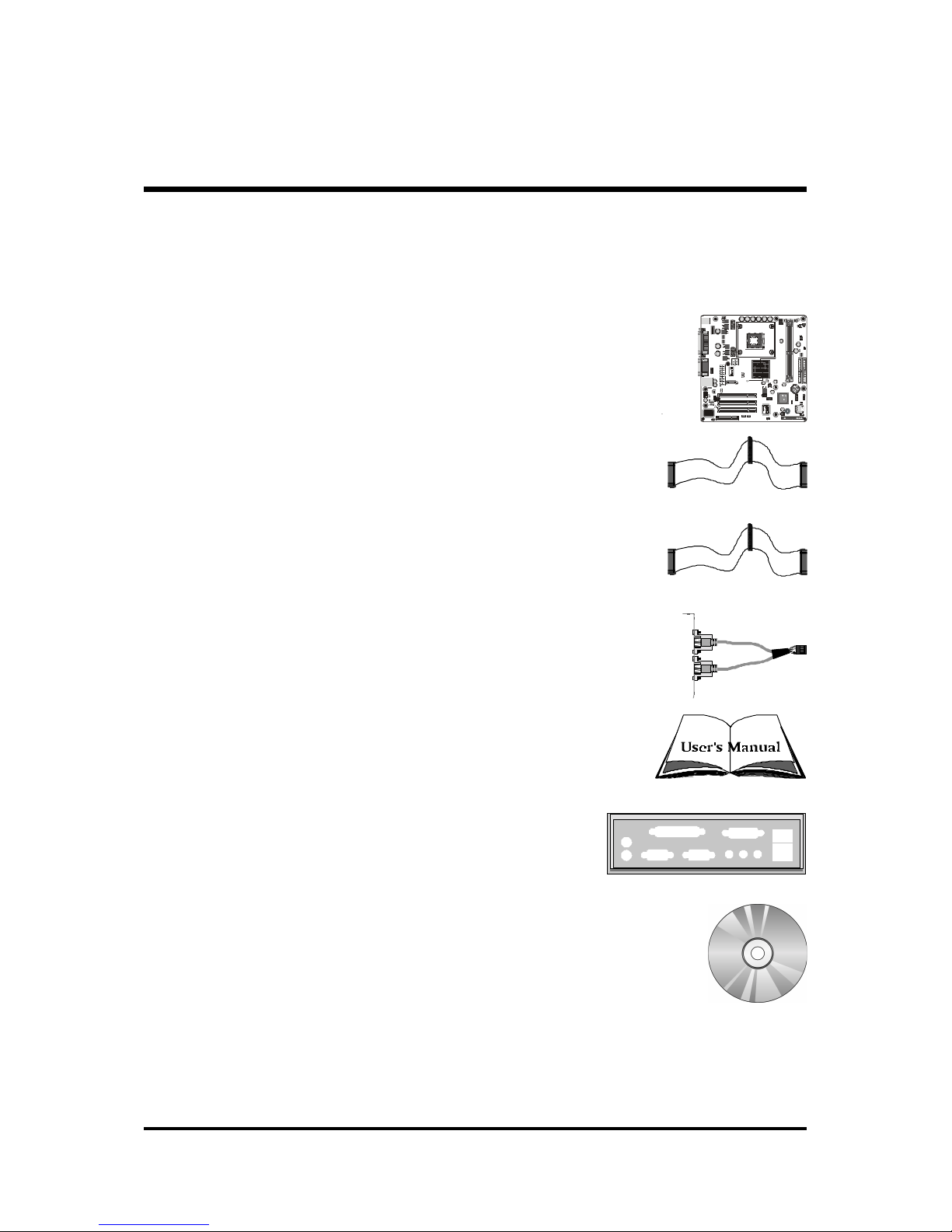
System board conforms to Micro ATX specification.
Board dimension: 244mm x 244mm.
!!
!!
! Advanced Featu es
"Low EMI -Low EMI -
Low EMI -Low EMI -
Low EMI - Built in spread spectrum and automatic clock shut-off of
unused PCI/SDRAM slots to reduce EMI.
"Dual Function Power Button -Dual Function Power Button -
Dual Function Power Button -Dual Function Power Button -
Dual Function Power Button - The system can be in one of two states,
one is Suspend mode and the other is Soft-Off mode. Pushing the power
button for less than 4 seconds places the system into Suspend mode.
When the power button is pressed for longer than 4 seconds, the system
entersSoft-Offmode.
"Modem Ring Power-On -Modem Ring Power-On -
Modem Ring Power-On -Modem Ring Power-On -
Modem Ring Power-On - The system can be powered on automatically
by theactivation ofmodem ringing.
"CPU Clock SettingCPU Clock Setting
CPU Clock SettingCPU Clock Setting
CPU Clock Setting - This item allows users to adjust CPU Host Clock in
BIOS.
"CPU Multiplier SettingCPU Multiplier Setting
CPU Multiplier SettingCPU Multiplier Setting
CPU Multiplier Setting - This item allows users to adjust CPU Multiplier
in BIOS.
"CPU Vcore SettingCPU Vcore Setting
CPU Vcore SettingCPU Vcore Setting
CPU Vcore Setting - This item allows users to select the CPU Vcore by
jumper.
!!
!!
! Intelligent Featu es
"Voltage Monitoring -Voltage Monitoring -
Voltage Monitoring -Voltage Monitoring -
Voltage Monitoring - Monitors various voltages of key elements, such as
theCPU, andother criticalsystem voltagelevels toensure stablecurrent
passing through mainboard components.
"Fan Status MonitoringFan Status Monitoring
Fan Status MonitoringFan Status Monitoring
Fan Status Monitoring --
--
- To prevent CPU from overheating, the CPU fan is
monitored for RPM and failure. (CPU Cooling FAN with RPM sensor is
required.)
"Temperature Monitoring -Temperature Monitoring -
Temperature Monitoring -Temperature Monitoring -
Temperature Monitoring -This item allows users to make sure whether the
CPUor systemruns ina suitable temperature.

- 8 -
Before removing or installing any of these devices including CPU, DIMMs, Add-OnBefore removing or installing any of these devices including CPU, DIMMs, Add-On
Before removing or installing any of these devices including CPU, DIMMs, Add-On
Cards, Cables, please make sure to unplug the onboard power connector.Cards, Cables, please make sure to unplug the onboard power connector.
Cards, Cables, please make sure to unplug the onboard power connector.
Thissection outlineshow toinstall andconfigure yourmainboard. Referto thefollowing
mainboard layout to help you to identify various jumpers, connectors, slots, and ports.
Then follow these steps designed to guide you through a quick and correct installation of
yoursystem.
3.1 Step-by-Step Installation
3 HARDWARE INSTALLATION
Accesso ies Of MB47N
1
RTL8100B
21 03OS1
20 31 TAIWA N
RMC
SECRET
FW82801DB
L204TB4Q
QC97ES
INTEL Q1
+
G1469497TD
204 KOREA
e
+
PhoenixBios
TM
D688 BI DS
PHOE NIX 1998
071776060
K
TS14.3 E2j
IR
IRU1010
PCNET
Ht20010203
PSKBM1
ATX1
CNRI
PCI3
PCI2
PCI1
WOM1 WOL1 I R 1
USB 2
USB3
FDD1
JP 3
CASFAN1
LSJ1
Sj1
IDE2
IDE1
CPU FAN1
DIMM2DIMM2
Three PCI Slots
SOCKET 478
ATX 12V
Select onboard
LAN - JP 4 CNR1
IR1
Wake On Ring
- WOM1
CPUFAN4
USB & LAN Connectors
Wake On LAN
- WOL1
Parallel Connector
Serial Port
Connector
VGA Port
CDIN 2
CDIN 1
Line-Out/Line-In
/Mic-In/Game/MIDI
Connectors
PS/2 Keyboard and
PS/2 Mouse Connectors
ATX 1
Audio 1
Two DIMM Slots
VID4- VID0
PWR FAN 1
PANEL1
BIOSflash
protectjumber-Jp3
CASFAN1Intel82801DB
SPEAKER1
Clear CMOS Jumper - JP 1
Floppy Connector
TwoIDEConnectors
Intel845-GChipset

- 9 -
Step 1
CPU Installat on:
This mainboard supports Intel Pentium 4/Celeron , Socket 478 series CPU.
Pleasefollow thestepas belowtofinish CPUinstallation.
Be careful of CPU orientation when you plug it into CPU socket.
1. Pull up the CPU socket level and up to 90-degree angle.
2. Locate Pin 1 in the socket and look for a black dot or cut edge on the CPU
upper interface. Match Pin 1 and cut edge, then insert the CPU into the
socket. CPU pin 1 and cut edge
CPU socket level up to
90 degree

- 10 -
3. Press down the CPU socket level and finish CPU installation.
Note:Note:
Note:Note:
Note: Ifyou do not match the CPU socket Pin 1 and CPU cut
edge well, it may damage the CPU.

- 11 -
Step 2.
Set Jumpers
The default jumper settings have been set for the common usage standard of
this mainboard. Therefore, you do not need to reset the jumpers unless you
requirespecial adjustmentsas anyof thefollowing cases:
1. Clear CMOS
2. BIOSProtect
3. LAN Select
4. CPU Core Voltage Select
Forfirst-time DIYsystem builders,we recommendthat youdo not change the
defaultjumper settingsifyou arenottotally familiarwith the mainboard
configurationprocedures. The factory-setdefaultsettings aretuned for opti-
mum system performance. For the advanced users who wish to customize
their system, section 3.2 Jumper Settings3.2 Jumper Settings
3.2 Jumper Settings3.2 Jumper Settings
3.2 Jumper Settings will provide detail information on
how to configure your mainboard manually.
Step 3
Install DDR SDRAM System Memory
Toinstall memory,insert DDRSDRAM memorymodule(s) in anyone ortwo
DIMMbanks. Notethat DDRSDRAM modulesare directionaland willnot
go in the DIMM banks if they are not properly oriented. After the module is
fullyinserted intotheDIMM bank,liftthe clipsof both sidesof the DIMM
bank to lock the module in place.

- 12 -
Step 4
Install Internal Per pherals n System Case
Before you install and connect the mainboard into your system case, we
recommendthat youfirst assemble allthe internalperipheraldevices intothe
computerhousing, includingbut not limitedto theharddisk drive(IDE/
HDD),floppy diskdrive(FDD), CD-ROMdrive,and ATXpowersupply unit.
Thiswill greatlyfacilitatein connectingto the mainboarddescribed below.
Toinstall IDE&FDD drives,followthis procedure:
1. Set the required jumpers on each device according to the instructions
provided by the manufacturer. (IDE devices, HDD, and CD-ROM have to
set jumpers to Master or Slave mode depending on whether you install
more than one device of each kind.)
2. Connect IDE cable and FDD cable on the back-panel of the internal
peripheral devices to the corresponding headers on board. Note that the
cable should be oriented with its colored stripe (usually red or magenta)
connected to pin#1 both on the mainboard IDE or FDD connector and on
the device as well.
3. Connect an available power cable from your system power supply unit
to the back-panel of each peripheral device. Note that the power cable is
directionaland cannotfit inif notproperly positioned.

- 13 -
Step 5
Mount the Ma nboard on the Computer Chass s
1. You may find that there are a lot of different mounting hole positions
both on your computer chassis and on the mainboard. To choose
correct mounting holes, the key point is to keep the back-panel of the
mainboard in a close fit with your system case, as shown below.
2. After deciding on the proper mounting holes, position the studsbetween
the frame of the chassis and the mainboard. The studs are used to fix the
mainboard and to keep a certain distance between the system chassis and
the mainboard, in order to avoid any electrical shorts between the board
and the metal frame of the chassis.
(If your computer case is already equipped with mounting studs, you will
need to tighten screws to attach the (mainboard.)
Note:Note:
Note:Note:
Note:In most computer housings, you will be able to find 4 or more attach-
ment points to install mounting studs and then fix the mainboard. If
there aren't enough matching holes, then make sure to install at least
4 mounting studs to ensure proper attachment of the mainboard.

- 14 -
Step 6
Connect Front Panel Sw tches/LEDs/Speaker/USB/AUDIO1
You can find there are several different cables already existing in the system
caseand originatingfromthe computersfront-panel devices (HDDLED,
Power LED, Reset Switch, PC Speaker, or USB devices etc.) These cables
serve to connect the front-panel switches, LEDs, and USB connectors to the
mainboard’ front-panel connectors group ( PANEL1, USB2/3, SPEAKER1,
AUDIO1),as shown below.
1.HDD LED
2. Green LED Indicator
3. Reset Switch
4.Power ON/OFF
5. VCC
6. USBP4 -
7. USBP4+
8.GROUND
9. KEY
10. USBPWR 1
11. USBP5 -
12. USBP5+
13.GROUND
14. NC
1
USB 2
1
USB 3
1
HDD LED
Green
LED
Power
ON/OFF Reset
Switch
N/CEmpty
PANEL 1
USB 2
#%
$
&
!
'
"
VCC
USBP4-
USBD4+
GROUND
KEY
USBPWR1
USBP5-
USBP5+
GROUND
NC
1
Empty
Green
LED
Power
Switch
HDD LED
Reset
Switch
N/C
1
!
"
PANEL1

- 15 -
15. VCC
16. USBP2 -
17. USBP2+
18.GROUND
19. KEY
20. USBPWR1
21. USBP3 -
22. USBP3+
23.GROUND
24. NC
SPEAKER1
1. SIGNAL
2. KEY
3. Ground
4. VCC
AUDIO 1
1. MICIN
2. AGND
3. MICBIAS
4. 5V
5. SPKOUTR
6. XSPKOUTR
7. KEY
8. EMPTY
9. SPKOUTL
10.XSPKOUTL
1
SPEAKER 1
4 3 2 1
AUDIO1
1
1
3
5
7
9
2
4
6
8
10
1
USB3
#
%
$
&
!
'
"
VCC
USBP2-
USBD2+
GROUND
KEY
USBPWR1
USBP3-
USBP3+
GROUND
NC

- 16 -
CD-IN 1
CD-IN 2
Step 7
Connect IDE and Floppy D sk Dr ves
1. IDE cable connector
2. Floppy cable connector
Step 8
Connect Other Internal Per pherals
1.CD-IN1/CD-IN2connectors
1
FDDI
IDE1IDE2
1
11

- 17 -
Step 9
Connect the Power Supply
1. System power connector
Step 10
Install Add-on Cards n Expans on Slots
1. PCI Card
2. CNR Card
ATX12V
ATX 1

- 18 -
Step 11
Connect External Per pherals to Back-Panel
You are now ready to put the computer case back together and get on to the
external peripherals connections to your system back-panel.
1. PS/2 Mouse and PS/2 Keyboard
2. ParallelPort
3. COM Port
4. VGA Port
5. MIDI/GAMEPort
6. AudioLine-Out /Mic-In / Line-InPorts
7. LANPort
8. USB Ports0 /1
foxconn
!"
%
$
&
#
Table of contents
Other Shuttle Motherboard manuals

Shuttle
Shuttle HOT-683 User manual

Shuttle
Shuttle ME21 User manual

Shuttle
Shuttle AK35GT User manual

Shuttle
Shuttle HOT-433 User manual

Shuttle
Shuttle AK37GT User manual

Shuttle
Shuttle HOT-559 User manual

Shuttle
Shuttle AN35 Ultra User manual

Shuttle
Shuttle ME21 User manual

Shuttle
Shuttle MV43VN User manual

Shuttle
Shuttle AB61 User manual

Shuttle
Shuttle Spacewalker AB40 User manual

Shuttle
Shuttle HOT-675 User manual

Shuttle
Shuttle Spacewalker MS51 User manual

Shuttle
Shuttle FB52 User manual

Shuttle
Shuttle AV18 User manual

Shuttle
Shuttle MT63 User manual

Shuttle
Shuttle FB77 User manual

Shuttle
Shuttle AK32A User manual

Shuttle
Shuttle AB52P User manual

Shuttle
Shuttle FS56 User manual