Shuttle HOT-675 User manual

HOT-675
Pentium™II processor
Based AGP MAIN BOARD
User's Manual

- 2 -
FCC Notice:
This equipment has been tested and found to comply with the limits for a Class B digital device, pursuant to Part 15 of FCC
Rules. These limits are designed to provide reasonable protection against harmful interference in a residential installation.
This equipment generates, uses and can radiate radio frequency energy. If not installed and used properly, in strict accor-
dance with the manufacturer’s instructions, may cause harmful interference to radio communications. However, there is no
guarantee that interference will not occur in a particular installation. If this equipment does cause interference to radio or
television reception, which can be determined by turning the equipment off and on, the user is encouraged to try to correct
the interference by one or more of the following measures :
Reorient or relocate the receiving antenna.
Increase the separation between the equipment and receiver.
Connect the equipment into an outlet on a circuit different from that to which the receiver is connected.
Consult the dealer or an experienced radio/television technician for help and for additional suggestions.
The user may find the following booklet prepared by the Federal Communications Commission helpful “How to Identify
and Resolve Radio-TV Interference Problems.” This booklet is available from the U.S. Government Printing Office.
Washington, DC 20402, Stock 004-000-00345-4
FCC Warning
The user is cautioned that changes or modifications not expressly approved by the manufacturer could void the user’s
authority to operate this equipment.
Note : In order for an installation of this product to maintain compliance with the limits for a Class B device, shielded
cables and power cord must be used.
CE Notice:
Following standards were applied to this product, in order to achieve compliance with the electromagnetic
compatibility :
- Immunity in accordance with EN 50082-1: 1992
- Emissions in accordance with EN 55022: 1987 Class B.
NOTICE
Copyright 1998.
All Right Reserved
Manual Ver 2.0
All information, documentation, and specifications contained in this manual are subject to change without prior
notification by the manufacturer.
The author assumes no responsibility for any errors or omissions which may appear in this document nor does
it make a commitment to update the information contained herein.
TRADEMARKS
Intel is a registered trademark of Intel Corporation
PentiumII Processor is a registered trademark of Intel Corporation
PC/AT is a registered trademark of International Business Machine Corporation.
PS/2 is a registered trademark of IBM Corporation.
All other brand and product names referred to in this manual are trademarks or registered trademarks of their
respective holders.

- 3 -
TABLEOFCONTENTS
T
T
PREFACE .............................................................................................................. 4
CHAPTER 1 INTRODUCTION....................................................................................... 5
Specification................................................................................................................................ 5
Accessories of HOT-675 ............................................................................................................. 7
CHAPTER 2 HARDWARE CONFIGURATION .................................................................... 8
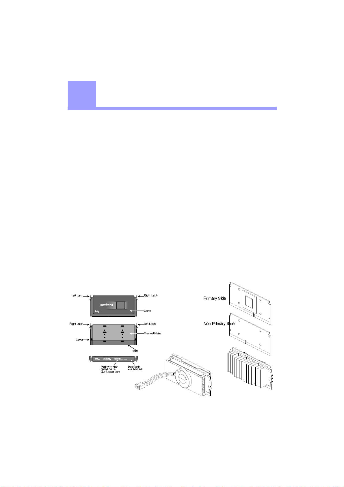
The Pentium II Processor ............................................................................................................ 8
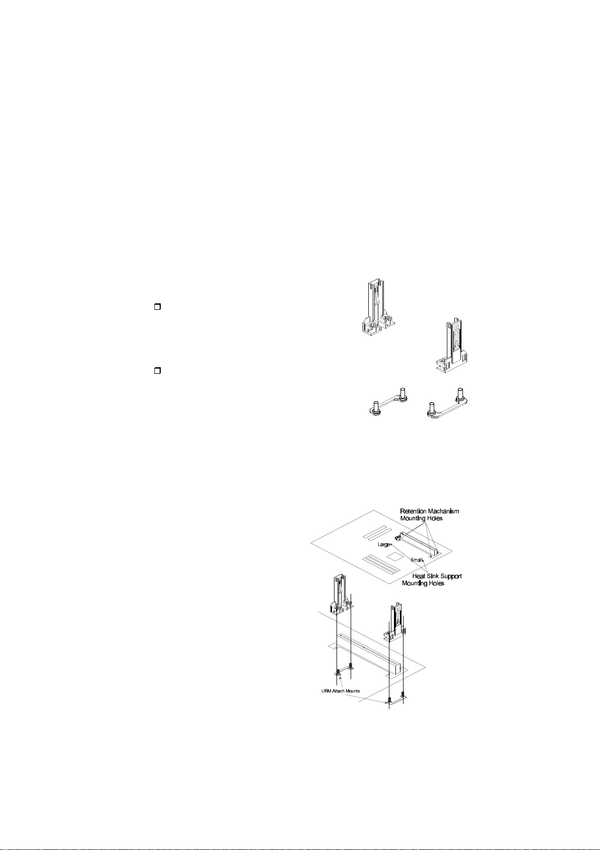
What does the URM (Universal Retention Mechanism) consist of .............................................. 9
Install the Universal Retention Mechanism ................................................................................. 9
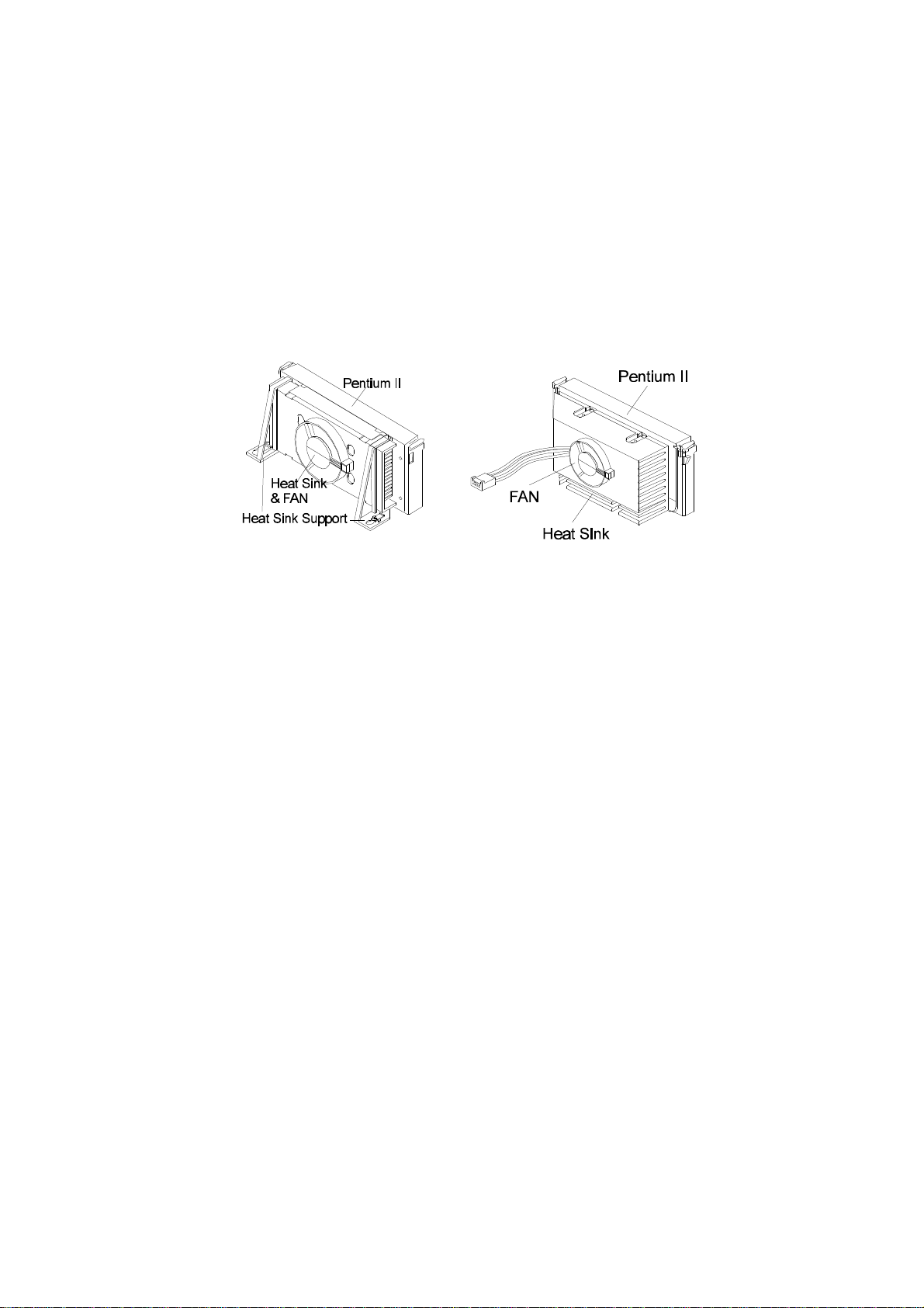
Install Pentium II Processor....................................................................................................... 11
Celeron Processor S.E.P.P only RM Assembly Procedure ......................................................... 12
Install Celeron Processor ........................................................................................................... 13
Install S.E.C.C.2 Processor ........................................................................................................ 14
Jumpers ..................................................................................................................................... 15
CPU Clock Speed Selection - JP1 and JP10 .............................................................................. 15
Clear CMOS - JP8 ..................................................................................................................... 18
Flash EEPROM Vpp - JP7......................................................................................................... 18
Keyboard & PS/2 Mouse Power-on Setting - JP2 ...................................................................... 18
On Board Audio Controller Setting - JP12 ................................................................................ 19
Connectors ................................................................................................................................ 19
CHAPTER 3 MEMORY CONFIGURATION ..................................................................... 22
CHAPTER 4 FLASH UTILITY .................................................................................... 23
CHAPTER 5 AWARD BIOS SETUP .......................................................................... 25
The Main Menu ......................................................................................................................... 26
Standard CMOS Setup............................................................................................................... 28
BIOS Features Setup ................................................................................................................. 30
Chipset Features Setup .............................................................................................................. 33
Power Management Setup ......................................................................................................... 36
PCI Configuration Setup ........................................................................................................... 39
Integrated Peripherals ................................................................................................................ 41
Password Setting ....................................................................................................................... 44
CHAPTER 6 ONBOARD AUDIO CONTROLLER ............................................................ 45
Introduction ............................................................................................................................... 45
General Specifications ............................................................................................................... 46
Connecting Audio Devices to 675 ............................................................................................. 47
Auto-installing Applications and Drivers .................................................................................. 49

- 4 -
PREFACE
P
P
HOT-675 is a highly integrated IBM PC/ATX compatible system board designed to
meet the industry's most demanding desktop applications.
Based on the Intel 82440BX AGPset chipset which support up to 500MHz PentiumTM II
processor with MMX technology.
HOT-675 is equipped with an Accelerated Graphics Port (A.G.P.), a high-performance
interconnect for graphic-intensive application, such as 3D applications. The A.G.P. is
independent of the PCI bus and is designed to exclusively use with graphical-display
devices. The HOT-675 supports 3.3 V A.G.P. devices with data transfer rates up to 133
MHz, allowing data throughput of 500 MB/sec.
The Intel's 82440BX AGPset chipset provides an integrated Bus Mastering IDE control-
ler with two high performance IDE interfaces which allows up to four IDE devices
connection and up to 33 MB/sec of data transfer rates.
The on-board I/O controller provides standard PC I/O functions:
floppy drive interface, two FIFO serial ports, an IrDA device port and a SPP/EPP/ECP
capable parallel port.
HOT-675 is built with two PCI local bus slots providing a high bandwidth data path for
data-movement intensive functions such as graphics, and with two ISA slots.
HOT-675 provides the foundation for cost effective, high performance and highly
expandable platforms, which delivers the latest in the Intel PentiumTM II processor and
new advanced chipset technology.

- 5 -
INTRODUCTION
The HOT-675 Mainboard is carefully designed for the demanding PC user who wants high perfor-
mance and many intelligent features in a compact package:
Intel Chipset:
Features Intel's 440BX AGPset with I/O subsystems.
CPUSupport:
Intel Pentium II processor 233/66 ~ 333/66 MHz and 350/100 ~ 500/100 MHz.
Celeron processor 266/66 ~ 333/66 MHz.
VersatileMemorySupports:
Supports three banks of normal or PC/100 SDRAM maximum memory size up to 768MB.
Configurable support for ECC (Error Checking and Correcting)
PCIand ISA Expansion Slots:
Provides two 32-bit PCI slots and two 16-bit ISA slot.
AGPSlot:
Supports Accelerated Graphics Port cards for high performance, component level interconnect
targeted at 3D graphical display applications.
Onboard I/O:
Provides one Floppy port; one PS/2 mouse connector; two high-speed UART compatible serial
ports and one parallel port with ECP and EPP capabilities. Serial Port 2 can also be directed from
COM2 to the Infrared Module for wireless connections.
OnboardPCIBus Master IDE Controller:
Two Ultra DMA/33 Bus Master IDE Ports supports four IDE devices up to 33 MB/sec IDE trans-
fers and supports Enhanced PIO Modes 3 and 4 and Bus Master IDE DMA Mode 2 devices.
Onboard20-pin ATX Power Supply:
Provides ATX power connector onboard supports soft-on/off function.
System BIOS:
Provides licensed Award V4.51PG BIOS on Flash EEPROM.
Supports Green PC, DMI and Bundled with NCR SCSI BIOS.
ACPI:
Support ACPI (Advanced Configuration and Power Interface) function. ACPI provide more
Energy Saving Features for the future operating system supporting OS Direct Power Management
(OSPM) functionality.
11
11

- 6 -
OnBoard Audio Controller:
Creative ES1371 AC97 digital controller
Advanced 64 polyphonic wavetable synthesis with additional DOS support
Full-Duples Record/Playback at up to 48KHz
Supports Microsoft DirectSound 3D
Digital effects engine for reverb, chorus, tone control
Board Size:
MicroATX form factor 244mm x 170mm.
Advanced Features:
CPU Plug & Play -- HOT-675 featuring CPU Plug & Play function, the user needn't to adjust
onboard system clock and CPU multiplier. When the system first power-on, BIOS will set CPU
clock speed to 233 MHz or 350 MHz (depend on CPU external frequency) automatically. If your
CPU speed higher than 233 MHz or 350 MHz, one thing you only have to do is entry BIOS to set
CPU speed to the higher one.
Low EMI -- Spread Spectrum built in - ±1.5% modulation and automatic clock shut-off of unused
PCI/SDRAMS slots to reduce the EMI.
Dual Function Power Button -- The system can be one of two states, one is Suspend mode and
the other is the Soft-off mode. Pushing the power button for less than 4 seconds will place the
system into Suspend mode. When push the power button for more than 4 seconds, the system
enters the Soft-off mode.
Wake-On-LAN -- The system will power-on automatically by activating of LAN.
(This function support Intel LAN card only).
Modem Ring Power-on -- The system will power-on automatically by activating of modem ring.
PS/2 Keyboard & Mouse Power-on -- The system will power-on automatically by stroke key-
board or double click PS/2 mouse.
MoreAdvancedFeatures (optional):
Voltages Monitoring -- System voltages levels are monitored to ensure stable current to main
board components.
System voltages include VCORE and VL2 for CPU, and +5V, +12V, -5V, -12V for system.
FAN Status Monitoring -- To prevent CPU overheat, CPU fans is monitored for RPM and failure.
(CPU Cooling FAN with RPM sensor is required)

- 7 -
ACCESSORIESOF HOT-675

- 8 -
HARDWARECONFIGURATION
22
22
The Pentium™ II Processor
Figure 2-1
Figure 2-2 Figure 2-3
The Pentium™ II and Celeron™ processor is the next member of the P6 processor family.
It combines the architectural advances in the Pentium Pro processor with the instruction set
extensions of MMX technology. It is fully compatible with the huge base of Intel architec-
ture-based PC software. Additional, the Pentium™ II processor delivers new levels of
performance for advance media and communications software including powerful, realistic
graphics and imaging capabilities, video conference, and the ability to run full-screen, full-
motion video. The combination of these advanced technologies makes the Pentium™ II
processor the ideal choice foe executing modem 32-bit compute-intensive and multimedia-
enhanced application work loads using advanced 32-bit operating systems.
The Pentium™ II and Celeron processor both have a separate, 32KB, on-chip, non-blocking
L1 cache which run at the processor frequency, Pentium™ II processor also has a 512KB or
256KB on-board L2 non-blocking cache runs at half the processor speed.
The Pentium™ II processor using Single Edge Contact Cartridge (S.E.C.C.) and S.E.C.C.2
packaging technology which enables high volume availability, improved handling protec-
tion.
The Celeron™ processor using Single Edge Processor Package. ( S.E.P.P.)
Figure 2-1 shows the front, rear and top views of Pentium™ II processor (without heat sink
mounted).
Figure 2-2 shows the S.E.C.C.2 package of Pentium™ II processor.
Figure 2-3 shows the primary and non-primary side of Celeron™ processor without heat
sink mounted and with heat sink mounted.

- 9 -
What does the URM (Universal Retention Mechanism) consist of
Pentium II processor requires the Retention Mechanism (RM) and optional Heat Sink
Support (HSS) to hold the base processor in the S.E.C. cartridge.(or SECC 2)
Following installation procedure will display how to install these mechanism.
Retention Mechanism package consists of 2 separate parts and optional Heat Sink Support
consists of 3 separate parts.
Normally, depend on the type of heat sink, Heat Sink Support is not always available. For
some heat sink attached on pentium II processor might not fit to install the Heat Sink
Support. The introduction of Heat Sink Support installation on this manual only for your
reference.
Universal Retention Mechanism (URM) -
Plastic Guide with captive nuts that hold the
S.E.C. Cartridge in the Slot1 connector.
(Refer to Figure 2-4)
URM Attach Mount (URMAM) -
Bolt/Bridge assemblies inserted up through
the bottom of the mainboard. Then secures the
URM to URMAM (two URMAM required per URM).
(Refer to Figure 2-5)
Figure 2-4
Figure 2-5
Install the Universal Retention Mechanism
Place the mainboard on a workbench (not in a chassis). Be sure that the mainboard is bare
(that is, no DIMMs, cables, or cards are installed).
Install the Retention Mechanism :
1. Finds out the Universal Retention
Mechanism (URM) Mounting Holes
of Slot1 on HOT-675 main board.
(Refer to Figure 2-6)
2. Install two Universal Retention
Mechanism Attach Mounts (URMAM)
with Bolt/Bridge assemblies inserted
up through the bottom of the
mainboard. (Notice the URMAM's
bridge orientation as Figure 2-7)
Figure 2-7
Figure 2-6

- 10 -
Figure 2-8 Figure 2-9
Install the Heat Sink Support: (optional)
If your Heat Sink comes with the Heat Sink suport then install it according to the instruction
comes with your Heat Sink.
Figure 2-8 and Figure 2-9 shows some Heat Sink examples.

- 11 -
Install Pentium II Processor
Figure 2-10
Figure 2-11
Push the latches on the processor toward the center of the processor until they click into place.
Hold the processor so that the fan shroud is facing toward the Heat Sink Support Base bar on
the mainboard. Slide the processor into the Universal Retention Mechanism. Ensure that the
alignment notch in the processor fits over the plug in Slot 1. Push the processor down firmly,
with even pressure on both sides of the top, until it is seated.
Push the latches on the processor outward until they click into place in the Universal Retention
Mechanism. The latches must be secured for proper electrical connection of the processor.
Attach the end of the power cable to the three-pin connector on the mainboard or to the CPU
fan connector on the HOT-675.

- 12 -
Celeron™ Processor S.E.P.P. Only Retention Mechanism Assembly
Procedures
These procedures have been included to help assemble the S.E.P.P. (Single
Edge Processor Package) only Retention Mechanism.
Please follow them exactly:
Required Components
SEPP (Figure 2-12)
Heatsink (Figure 2-13)
Heatsink Retention Clip (Figure 2-14)
Primary Side
Figure 2-13
Figure 2-14
Procedures
Assemble all parts on a static free bench using
proper operator grounding and an ESD mat.
Carefully insert all four heatsink clip legs into
SEPP. (Figure 2-15)
Clip base must be located on the non-primary
side.(Figure 2-16) FYI - The side of the clip plate
which touches the substrate is covered with a
mylar insulator. This insulator prevents the clip
from shorting lines on the substrate.
Before you fully engage two legs of the clip into
the heatsink (Figure 2-17), make sure you remove
the blue film covering the thermal interface. The
blue film protects the thermal interface from
damage during shipping.
Grasp the heatsink clip assembly between the clip
base and the heatsink. Do not bend or apply
pressure directly to SEPP.
Using a nonmetallic stock or screw driver, push
the remaining two clip legs into the heatsink.
Caution: Take care not to contact passively or
scratch SEPP when using screw driver or bar
stock.
Verify that all the feet on the clip are fully en-
gaged and seated on the heatsink. (Figure 2-18)
Non-primary Side
Non-primary Side
Primary Side
Figure 2-18
Figure 2-17
Figure 2-16
Figure 2-15
Figure 2-12

- 13 -
Install Celeron™ Processor
Hold the processor unit so that the Heat sink faces toward the DIMM sockets on the mainboard.
Insert the processor into the Universal Retention Mechanism. Press the processor down firmly
with even pressure on both sides of the top until it is seated.
(Refer to Figure 2-19 and Figure 2-20)
Figure 2-19
Figure 2-20

- 14 -
Install S.E.C.C.2™ Processor
Hold the processor unit so that the Heat sink faces toward the DIMM sockets on the mainboard.
Insert the processor into the Universal Retention Mechanism. Press the processor down firmly
with even pressure on both sides of the top until it is seated.
(Refer to Figure 2-21 and Figure 2-22)
Figure 2-21
Figure 2-22

- 15 -
Jumpers
Several hardware settings are made through the use of jumper caps to connect jumper pins on
the main board. The jumper's pin 1 on main board will be on the top or on the left when hold-
ing the main board with the keyboard connector away from yourself.
Jumpers with two pins will be shown as for Close (On) and for Open (Off).
To connect the pins, simply place a plastic jumper cap over the two pins.
HOT-675 featuring CPU Plug & Play function, the user needn't to adjust onboard system clock
and CPU multiplier. When the system power-on first time, BIOS will set CPU clock
speed to 233 MHz or 350 MHz (depend on CPU external frequency) automatically. If
your CPU speed higher than 233 MHz or 350 MHz, you only have to entry BIOS to set CPU
speed to the higher one.
HOT-675 mainboard features a clock generator to provide adjustable system clock frequency.
JP1 is a 6-pin jumpers which determine the system clock frequency 66 MHz to 133 MHz.
CPU Plug & Play function is supported by 66MHz / 100MHz.
HOT-675 mainboard provides Jumper group of JP10 to figure the CPU core clock multiplier.
By inserting mini jumpers on MANUAL group, the user can figure the Host Bus Clock/CPU
Core Clock ratio (multiplier) manually.
CPU Plug & Play function is supported when an Jumper Pack inserted on
AUTOgroup.
Listed diagrams on right side show the sample position on jumper group of JP10:
1) Setting CPU Clock from BIOS
- jumper pack on AUTO.
(Factory default)
2) Adjust multiplier manually from hardware
- jumper pack on MANUAL, multiplier set to 5X manually.
Figure 2-23 shows the position of JP1 and JP10 on the mainboard.
Figure 2-23
CPU Clock Speed Selection - JP1 and JP10

- 16 -
CPU Clock Configuration Table (Table 2-1) shows the Celeron 266MHz ~ 333MHz and Pentium
II 233MHz ~ 500MHz quick setting on the mainboard.
Table 2-2 shows the adjustable CPU Host Clock on jumper JP1.
Table 2-3 shows the adjustable CPU Clock Ratio on jumper group JP10.
CPUConfigurationTable
Pentium II
/Celeron
Processor
System
Clock Multiplier
233 MHz 66 MHz 3.5
266 MHz 66 MHz 4
300 MHz 66 MHz 4.5
333 MHz 66 MHz 5
CPUHost Clock Configuration Table
CPU
HostClock
JP1
66MHzbased
processor
JP1
100MHzbased
processor
66 MHz
75 MHz
83 MHz
100 MHz
(Default)
103 MHz
112 MHz
124 MHz
133 MHz
N/A
N/A
N/A
PentiumII
ProcessorSystem
Clock Multiplier
350 MHz100 MHz3.5
400 MHz100 MHz4
450 MHz100 MHz4.5
500 MHz100 MHz5
Table 2-1
N/A
N/A Table 2-2

- 17 -
HOT-675 mainboard provides a Jumper group JP10 to set CPU Speed configure by BIOS or by
hardware jumper.
By inserting jumper pack on Row B-C group, the user can Soft-Configure the CPU Host Clock and
CPU Clock Ratio from BIOS.
By removeing jumper pack from Row B-C group and inserting mini jumpers on Row A-B group
properly, the user can configure the CPU Clock Ration (multiplier) manually.
Note: 73, 83 MHz are for 66 MHz based and 103 ~ 133 MHz are for 100 MHz based processor over-
clock usage, it is not a recommended general practice.
CPUClock
RatioJP10 CPUClock
RatioJP10
BIOSSetup
2x ~5x
(Default)
3.5x
(233 /66 )
(350 /100 )
4x
(266 /66 )
(400 /100 )
2x
(133 /66 )
(200 /100 )
4.5x
(300 /66 )
(450 /100 )
2.5x
(166 /66 )
(250 /100 )
5x
(333 /66 )
(500 /100 )
3x
(200 /66 )
(300 /100 )
CPUClock Ratio Table
Table 2-3
Special Tip for User's Reference Only
HOT-675 mainboard provides a special Jumper J19
to overspeed your 66 MHz based Pentium II processor
to 100 MHz.
Normally, CPU Host Clock 100 ~ 133 MHz are not
available for 66 MHz based processor no matter Soft-
Configure or Hard-Configure.
But, when pull out mini jumper from J19 (let it open),
the user can Hard-Configure your 66 MHz based
processor to 100 MHz based. For example, overspeed
your 266 MHz (66 MHz x 4) Celeron to
300 MHz (100 x 3) or more.
Figure 2-24

- 18 -
HOT-675 mainboard supports two types
of Flash EEPROM: 5 volt and 12 volt.
By setting up jumper JP7, the main
board can use both 5V or 12V flash
EEPROM with new system BIOS files
as they come available.
JP7 Pin 1-2 Close
for 5V Flash EEPROM
JP7 Pin 2-3 Close
for 12V Flash EEPROM
Clear CMOS - JP8
Flash EEPROM Vpp - JP7
HOT-675 mainboard supports jumper JP8 for discharging mainboard's CMOS memory.
This jumper can clear the CMOS data stored in the Giga I/O chip. To clear the CMOS data
please follow listed steps:
1) Turn off the PC,
2) Remove mini jumper from JP8 pin 1-2,
3) Insert mini jumper to JP8 pin 2-3 for a brief while,
4) Remove mini jumper from JP8 in 2-3,
5) Reinsert mini jumper to JP8 pin 1-2,
6) Turn on the PC.
Figure 2-25
Keyboard & PS/2 Mouse Power-On Setting - JP2
HOT-675 mainboard provides an optional power-on function by stroke any key (or hot-key)
on keyboard or double click on PS/2 mouse.
Note: Power-on by serial mouse is not supported
JP2 is the jumper used to set the functions of keyboard & PS/2 mouse power-on Enabled or
Disabled.
When you enabled K/B & PS/2 Mouse Power-ON function, you also have to set the proper
item on POWER ON function category of Integrated Peripherals of BIOS setup.
K/B&PS/2Mouse Power-OnJP2
Keyboard&
PS/2Mouse
Power-On
Disabled
PS/2Mouse
Power-On
Enabled
Keyboard&
PS/2Mouse
Power-On
Enabled
Table 2-4

- 19 -
On Board Audio Controller Setting - JP12
HOT-675 mainboard provides on-board PnP 64 voices
wavetable sound chip which based on Creative ES1371
AC97 PnP 3D integrated audio controller chip. Jumper
JP12 is used to enabled or disabled it.
On-board Audio Controller
Disabled
On-board Audio Controller
Enabled
Figure 2-26
Connectors
Front Panel Connectors
ATX Power On/Off Switch Connector
- S2
Attach a 2-pin momentary type switch to this connector
for turning on or off your ATX power supply.
HDD LED Connector - S3
Attach a 2-pin IDE drive LED cable to this connector.
The LED lights when an IDE device is active.
Hardware Reset Connector - J15
Attach 2-pin hardware reset switch to it. Closing the
reset switch restarts the system.
Speaker Connector - JP6
PC speaker connector may attach a 4-pin PC speaker cable from the case to this connector.
EPMI Connector - JP11(1-2)
Hardware System Management Interface connector may attach a 2-pin momentary switch to it. When
push it will force system get into power saving mode, and the system will resume when switch is
pushed again.
GLED Connector - JP11(3-4)
Attach a 2-pin Green LED cable to it. The Green LED lights when the system get intopower saving
mode.
Figure 2-27

- 20 -
Back Panel Connectors
Figure 2-29
Figure 2-28
Figure 2-30
COM1/COM2 Connectors
Attach COM1/COM2 device cables to these connectors.
PS/2 Keyboard & PS/2 Mouse Connector
Two 6-pin female PS/2 keyboard & Mouse Connectors is located at the rear of the main board.
PS/2 Mouse on top of connector and PS/2 Keyboard on the bottom of connector. Plug the PS/2
keyboard and mouse jack into this connector.
Parallel Port Connector
A 25-pin female connector is located at the rear of the main board. Plug the parallel port device
cable into this connector.
USB1/USB2 Port Connectors
Two female connectors are located at the rear of the board.
Plug the USB devices jack into this connector.
OtherConnectors
ATX Power Supply Connector - J4
It is a twenty-pin male header connector. Plug the connector
from the power directly onto the board connector while the
plug of the power supply will only insert in one orientation.
Fine the proper orientation and push down firmly making
sure that the pins are aligned.
IR Connector - J3
Infrared device connector may attach a 5-pin infrared
device cable to this connector for enabling the infrared
transfer function. This mainboard meets the specification
of ASKIR and HPSIR. Figure 2-30 shows J3's
pin assignment.
Table of contents
Other Shuttle Motherboard manuals

Shuttle
Shuttle SH610R4 Series User manual

Shuttle
Shuttle MV43 User manual

Shuttle
Shuttle HOT-617 User manual

Shuttle
Shuttle av61 User manual

Shuttle
Shuttle FN25 User manual

Shuttle
Shuttle AV18 User manual

Shuttle
Shuttle AB52 User manual

Shuttle
Shuttle HOT-687V User manual

Shuttle
Shuttle AV49V User manual

Shuttle
Shuttle AK12 User manual

Shuttle
Shuttle MZ11 User manual

Shuttle
Shuttle HOT-641/P User manual

Shuttle
Shuttle FB52 User manual

Shuttle
Shuttle HOT-559 User manual

Shuttle
Shuttle MV21 User manual

Shuttle
Shuttle AK32A User manual

Shuttle
Shuttle HOT-595 User manual

Shuttle
Shuttle HOT-649A User manual

Shuttle
Shuttle FX43G User manual

Shuttle
Shuttle AE25 User manual