SIBELL IPOD-SB2IRE User manual

2 Megapixel Network Camera
User Manual
Please read this manual carefully before use of the products and preserve for reference
purposes. Specifications are subject to change without notice*

Notes on Safety
■Please use the specified power supply to connect.
■Do not attempt to disassemble the camera; in order to prevent electric shock, do not
remove screws or covers.
■There are no user-serviceable parts inside. Please contact the nearest service center as
soon as possible if there is any failure.
■Avoid shock, vibration, and heavy pressure which can cause damage to the product.
■Do not use corrosive detergent to clean the main body of the camera. If necessary, use a
soft dry cloth to wipe dirt; for hard contamination, use neutral detergent. Any cleanser for
high-grade furniture is applicable.
■Avoid aiming the camera directly towards extremely bright objects, such as the sun, as
this may damage the image sensor.
■Please follow the instructions to install the camera. Do not reverse the camera or the
reversing image will be received.
■Do not operate if temperature, humidity and power supply are beyond the limited
stipulations.
■Keep away from heat sources such as radiators, heat registers, stove, etc.
■Do not expose the product to the direct airflow from an air conditioner.
■This is a product manual NOT a warranty. We may reserve the rights of amending the
typographical errors, inconsistencies with the latest version, software upgrades and
product improvements, interpretation, and modification. These changes will be published
in the latest version without special notification.
■When this product is in use, the relevant contents of Microsoft,Apple and Google will be
involved in. The pictures and screenshots in this manual are only used to explain the
usage of our product. The ownerships of trademarks, logos and other intellectual
properties related to Microsoft, Apple and Google belong to the above-mentioned
companies.
■This manual is suitable for IR waterproof network camera. All pictures and examples
used in the manual are for reference only.

Table of Contents
1Introduction ...................................................................................................................1
2IE Remote Access...........................................................................................................2
2.1 LAN...................................................................................................................2
2.1.1 Access through IP-Tool ............................................................................2
2.1.2 Directly Access through IE.......................................................................3
2.2 WAN..................................................................................................................5
3Remote Preview .............................................................................................................7
3.1 The Remote Preview Interface...........................................................................7
4Remote Live Surveillance..............................................................................................8
4.1 System Configuration ........................................................................................8
4.1.1 Basic Information .....................................................................................8
4.1.2 Date & Time.............................................................................................8
4.1.3 Local Configuration..................................................................................9
4.2 Image Configuration..........................................................................................9
4.2.1 Display Configuration ..............................................................................9
4.2.2 Video Stream..........................................................................................10
4.2.3 OSD Configuration.................................................................................11
4.2.4 Video Mask ............................................................................................11
4.2.5 ROI Configuration..................................................................................12
4.3 Alarm Configuration........................................................................................13
4.3.1 Motion Detection....................................................................................13
4.3.2 Alarm Server ..........................................................................................15
4.4 Network Configuration....................................................................................15
4.4.1 TCP/IPv4................................................................................................15
4.4.2 Port .........................................................................................................16
4.4.3 Central Server.........................................................................................16
4.4.4 DDNS Configuration..............................................................................17
4.4.5 SNMP.....................................................................................................18
4.4.6 RTSP.......................................................................................................19
4.4.7 UPNP......................................................................................................20
4.4.8 Mail configuration..................................................................................20
4.4.9 FTP Setting.............................................................................................21
4.5 Security Configuration.....................................................................................22
4.5.1 User Configuration .................................................................................22
4.5.2 Online Video User ..................................................................................24
4.5.3 Block and Allow List..............................................................................24
4.6 Maintenance.....................................................................................................24
4.6.1 Backup & Restore...................................................................................24
4.6.2 Reboot Device ........................................................................................25
4.6.3 Upgrade ..................................................................................................25
4.6.4 Log .........................................................................................................26

Network Camera User Manual
5Search ...........................................................................................................................27
Appendix................................................................................................................................28
Appendix 1 Q & A ..............................................................................................................28
Appendix 2 Specifications..................................................................................................29
1
Network Camera User Manual
1Introduction
This IP-CAMERA (short for IP-CAM) is designed for high performance CCTV solutions. It
adopts state of the art video processing chips. It utilizes most advanced technologies, such as
video encoding and decoding technology, complies with the TCP/IP protocol, SoC, etc to
ensure this system more stable and reliable.
This product is widely used in banks, telecommunication systems, electricity power
departments, law systems, factories, storehouses, uptowns, etc. In addition, it is also an ideal
choice for surveillance sites with middle or high risks.
Main Features
ICR auto switch, true day/night
3D DNR, digital WDR
ROI coding
Support smart phone, iPad, remote monitoring
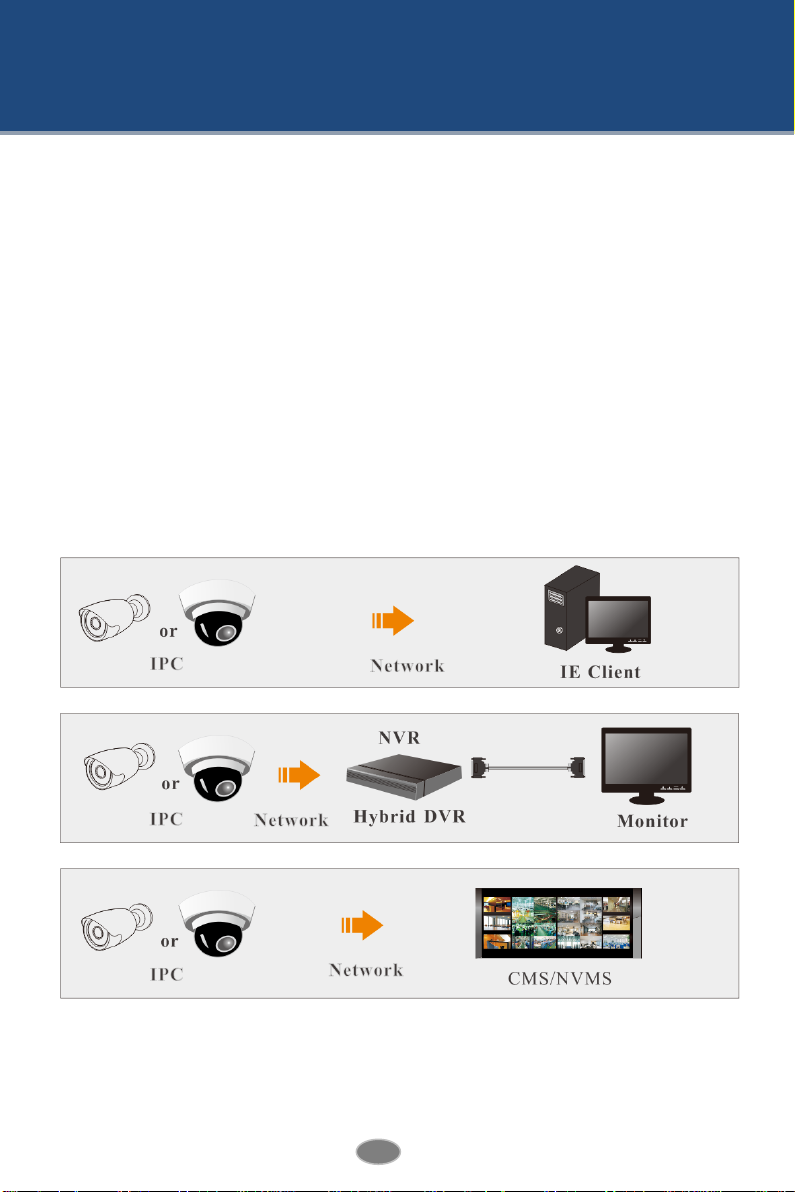
Surveillance Application
2
Network Camera User Manual
2IE Remote Access
You may connect IP-Cam via LAN or WAN. Here only take IE browser (6.0) for example. The
details are as follows:
2.1 LAN
In LAN, there are two ways to access IP-Cam: 1. access through IP-Tool; 2. directly access
through IE browser.
2.1.1 Access through IP-Tool
Network connection:
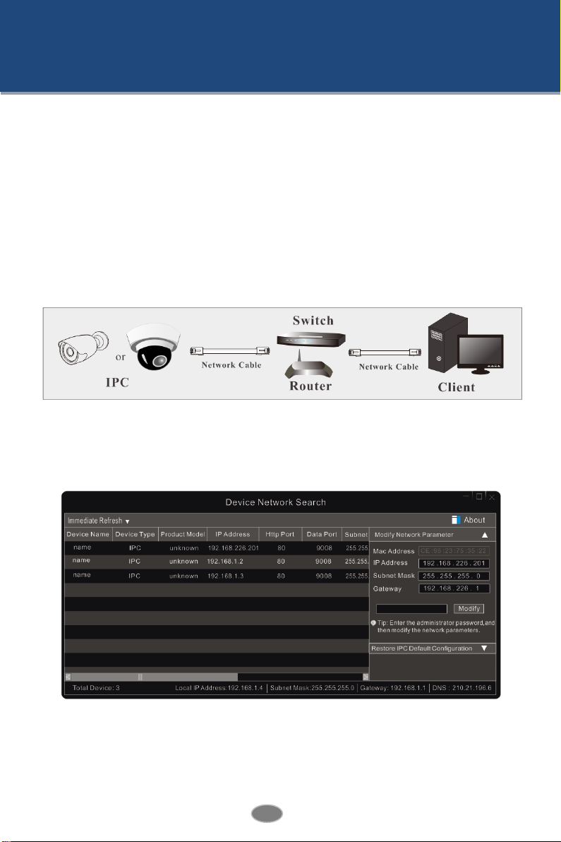
①Make sure the PC and IP-Cam are connected to the LAN and the IP-Tool is installed in the
PC from the CD.
②Double click the IP-Tool icon on the desktop to run this software as shown below:
③Modify the IP address. The default IP address of this camera is 192.168.226.201. Click the
information of the camera listed in the above table to show the network information on the
right hand. Modify the IP address and gateway of the camera and make sure its network
address is in the same local network segment as the computer’s. Please modify the IP address
3
Network Camera User Manual
of your device according to the practical situation.
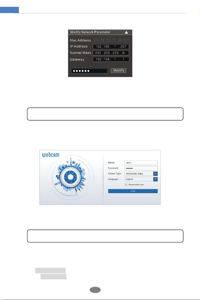
For example, the IP address of your computer is 192.168.1.4. So the IP address of the camera
shall be changed to 192.168.1.X. After modification, please input the password of the
administrator and click “Modify” button to modify the setting.
④Double click the IP address and then the system will pop up the IE browser to connect
IP-CAM. IE browser will auto download the Active X control. After downloading, a login
window will pop up as shown below.
Input the username and password to log in. If you input the wrong password for the first time,
you shall wait for 10 seconds and then input the right password.
2.1.2 DirectlyAccess through IE
The default network settings are as shown below:
IP address: 192.168.226.201
Subnet Mask: 255.255.255.0
The default password of the administrator is “123456”.
The default username is “admin”; the default password is “123456”.
4
Network Camera User Manual
Gateway: 192.168.226.1
HTTP: 80
Data port: 9008
You may use the above default settings when you log in the camera for the first time. You may
directly connect the camera to the computer through network cable.
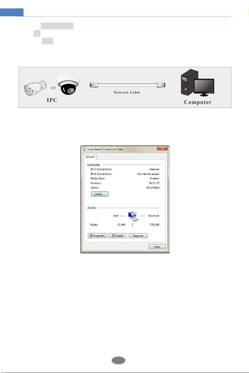
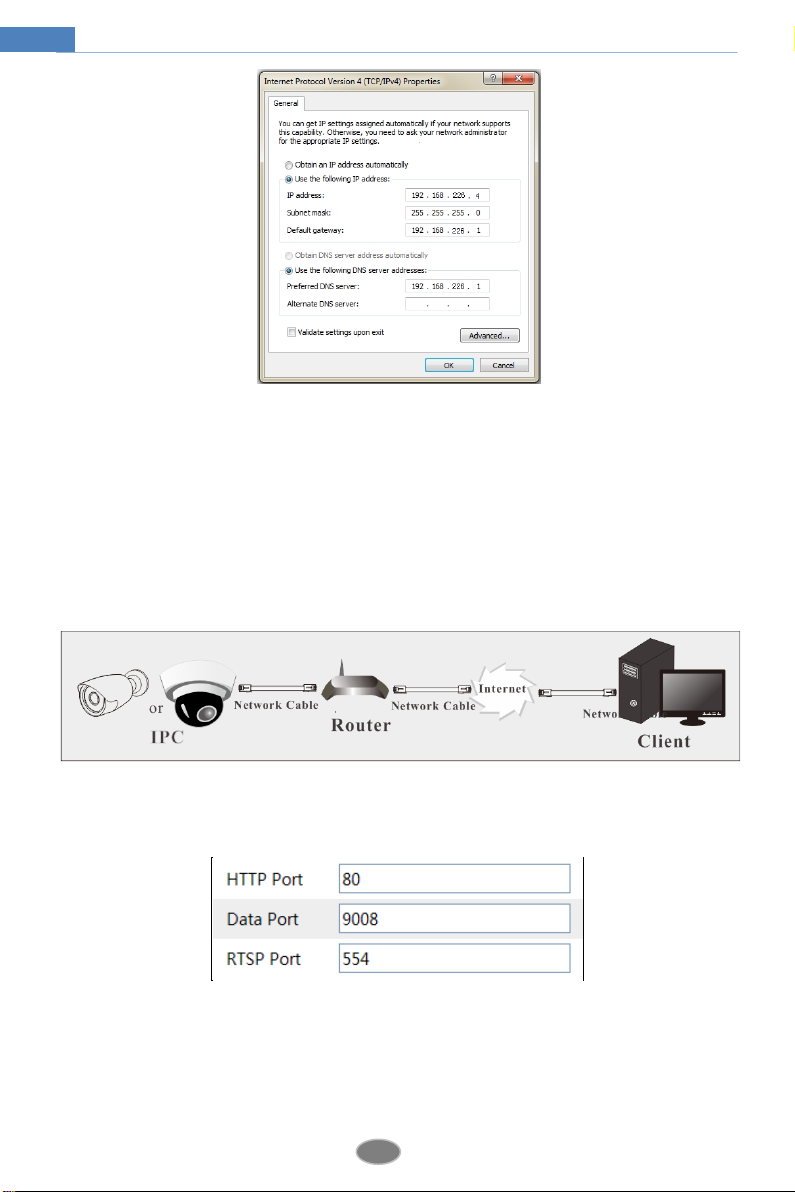
①Manually set the IP address of the PC and the network segment should be as the same as
the default settings of the IP camera. Open the network and share center. Click “Local Area
Connection” to pop up the following window.
Select “Properties” and then select internet protocol according to the actual situation (for
example: IPv4). Next, click “Properties” button to set the network of the PC.
5
Network Camera User Manual
②Open the IE browser and input the default address of IP-CAM and confirm. The IE
browser will download Active X control automatically.
③After downloading Active X control, the login dialog box will pop up.
④Input the default username and password and then enter to view.
2.2 WAN
Access through the router or virtual server
①Make sure the camera is well connected via LAN and then log in the camera via LAN. Go
to ConfigNetwork Port menu to set the port number.
②Go to Config Network TCP/IPv4 menu to modify the IP address.
6
Network Camera User Manual
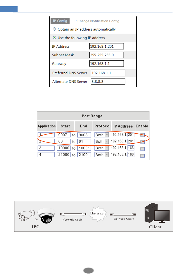
③Go to the router’s management interface through IE browser to forward the IP address and
port of the camera in the “Virtual Server”.
Router Setup
④Open the IE browser and input its WAN IP and http port to access.
Access through static IP
Network connection
The setting steps are as follow:
①Go to ConfigNetwork ConfigPort menu to set the port number.
②Go to Config Network ConfigIP Address menu to set the IP address. Check “Use the
following IP address” and then input the static IP address and other parameters.
③Open the IE browser and input its WAN IP and http port to access.

7
Network Camera User Manual
3Remote Preview
3.1 The Remote Preview Interface
After you log in, you will see the following window.
The following table is the instructions of the icons on the remote preview interface.
Icon
Description
Icon
Description
Motion alarm indicator
icon
Start/stop live view
Original size
Snap
Appropriate size
Start/stop record
Auto
Zoom in
Full screen
Zoom out
When motion detection alarm is triggered, the people icon will turn red.
In full screen mode, right click to exit.
8
Network Camera User Manual
4Remote Live Surveillance
4.1 System Configuration
The “System Configuration” includes three submenus: Basic Information, Date & Time and
Local Configuration.
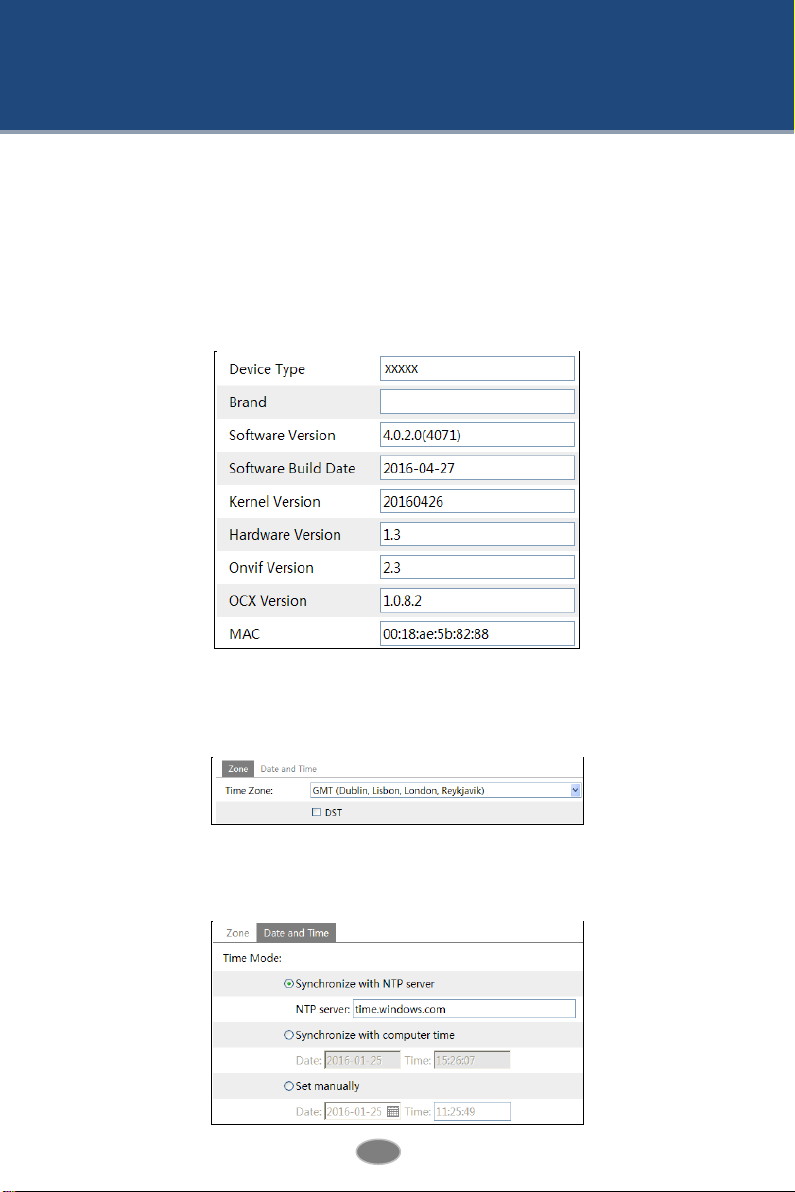
4.1.1 Basic Information
In the Basic Information interface, you can check the relative information of the device.
4.1.2 Date & Time
Go to ConfigSystemDate and Time. Please refer to the following interface.
You can select the time zone and DST as required.
Click “Date and Time” to set the time mode .
9
Network Camera User Manual
4.1.3 Local Configuration
Go to ConfigSystemLocal Config. You can set the storage path of the captured pictures
and video records.
4.2 Image Configuration
Image Configuration includes five submenus: Display, Video/Audio, OSD, Video Mask and
ROI Config.
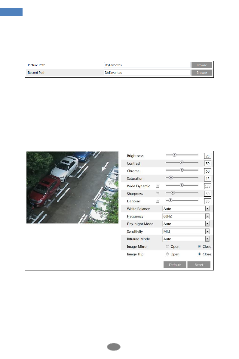
4.2.1 Display Configuration
Many parameters of the camera can be set in display configuration interface such as brightness,
contrast, chroma, saturation wide dynamic, etc.
Brightness: Set the brightness level of the camera’s image.
Contrast: Set the color difference between the brightest and darkest parts.
Chroma: Set the total color degree of the image.
Saturation: Set the degree of color purity. The purer the color is, the brighter the image is.
Wide Dynamic: It helps the camera provide clear images even under back light
circumstances. When there are both very bright and very dark areas simultaneously in the
field of view, WDR balances the brightness level of the whole image and provide clear images
with details.
10
Network Camera User Manual
Sharpness: Set the resolution level of the image plane and the sharpness level of the image
edge.
Denoise: Decrease the noise and make the image more thorough. Increasing the value will
make the noise reduction effect better but it will reduce the image resolution.
White Balance: Adjust the color temperature according to the environment automatically.
Frequency: 50HZ and 60HZ can be optional.
Day-night Mode: Please choose the mode as needed.
Sensitivity: High, middle and low can be selected.
Infrared Mode: You may choose “ ON”, “OFF” and “Auto” as required.
Image Mirror: Reverse the current video image right and left.
Image Flip: Turn the current video image upside down.
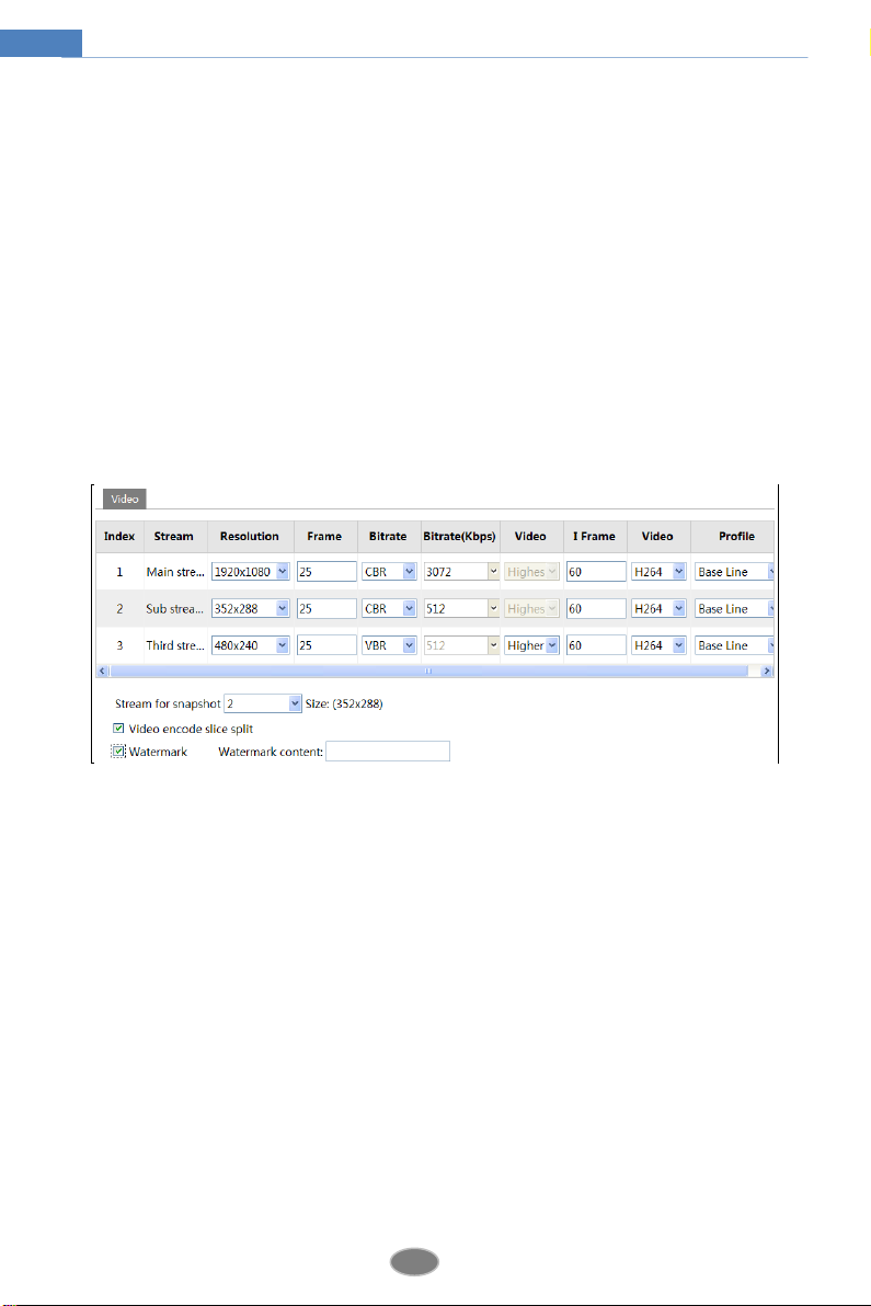
4.2.2 Video Stream
The following interface will be displayed by clicking ConfigImageVideo/Audio.
In this interface, you can set the resolution, frame rate, bitrate type, video quality and so on
subject to the actual network condition.
Three video streams can be adjustable.
Resolution: The higher the resolution is, the clearer the image is.
Frame rate: The higher the frame rate is, the more fluency the video is. However, more storage
room will be taken up.
Bitrate type: Including CBR and VBR. CBR means that no matter how changeable the video
resources are, the compression bitrate keeps constant. This will not only facilitate the image
quality better in a constant bitrate but also help to calculate the capacity of the recording. VBR
means that the compression bitrate can be adjustable according to the change of the video
resources. This will help to optimize the network bandwidth.
Video Quality: When VBR is selected, you need to choose image quality. The higher the image
quality you choose, the more bitrate will be required.
Bitrate: Please choose it according to the actual network situation.
I Frame interval: It is recommended to use the default value. If the value is over high, the
read speed of the group of pictures will be slow resulting in the quality loss of the video.
Video encoding profile: Baseline and main profile are optional. Baseline profile is mainly
11
Network Camera User Manual
used in interactive application with low complexity and delay. Main profile is mainly used for
higher coding requirement.
Stream of snapping photos: Please select it according to the actual situation.
Video encode slice split: If enabled, you may get more fluency image even though using the
low-performance PC.
Watermark: If selected, you can input the watermark theme. You may check the watermark
when playing back the local record in the search interface, lest the record files is tampered.
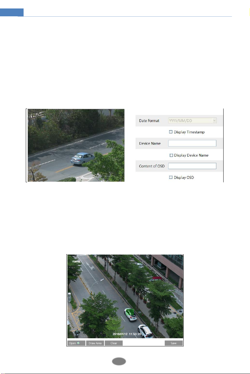
4.2.3 OSD Configuration
Go to ConfigImageOSD menu to display the interface as shown below:
You may set time stamp, device name and OSD here. After enabling the corresponding display
and entering the content, drag them to change their position. Then press the “Save” button to
save the settings.
4.2.4 Video Mask
Go to ConfigImageVideo Mask menu to display the interface as shown below. You can
set 4 mask areas at most.
12
Network Camera User Manual
To set up video mask
1. Open video mask.
2. Click “Draw Area” button and then drag the mouse to draw the video mask area.
3. Click “Save” button to save the settings.
4. Return to the live to see the following picture.
Clear the video mask:
Go to video mask menu and then click “Clear” button to delete the current video mask area.
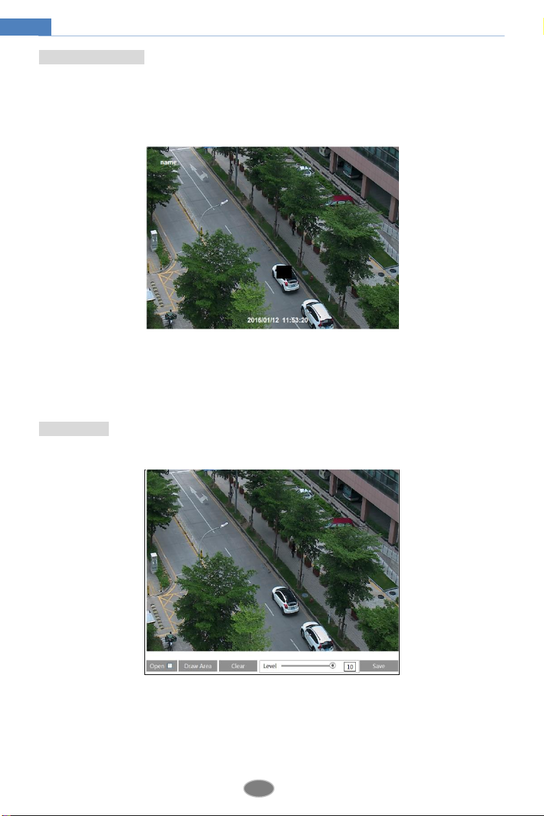
4.2.5 ROI Configuration
To set up ROI
1. Go to Video ConfigROI Config menu.
2. Check “Open” and then click “Draw Area” button.
3. Drag the mouse to set the ROI area.
4. Set the level.
5. Click “Save” button to save the settings.
Now, you will see the selected ROI area is clearer than other areas especially in low bitrate

13
Network Camera User Manual
condition.
4.3 Alarm Configuration
Alarm configuration includes two submenus: Motion Detection and Alarm Server.
4.3.1 Motion Detection
To set motion detection:
1. Go to ConfigAlarmMotion Detection to set motion detection alarm.
Check “Enable Alarm” check box to activate motion based alarm, choose alarm holding time
and set alarm trigger options.
Trigger Email: If the email and attach picture checkbox is checked (Email address shall be set
first in the Mail config interface), the triggered snap pictures and event will be sent into those
addresses.
Trigger FTP: If “Uploading picture” is checked, the triggered snap pictures will be sent into
FTP server address. Please refer to FTP configuration chapter for more details.
2. Set motion detection area and sensitivity. Click “Area and Sensitivity” tab to see the
following sub-menu.

14
Network Camera User Manual
Move the “Sensitivity” scroll bar to set the sensitivity.
Check “Add” and click “Draw” button and move mouse to select the motion detection area;
Select “Erase” and move the mouse to clear motion detection area.
After that, click “Save” to save the settings.
3. Set the schedule of the motion detection. Click “Schedule” tab to set the schedule of the
motion detection.
Week schedule

15
Network Camera User Manual
Set the alarm time from Monday to Sunday for alarm everyday in one week. The lengthwise
means one day of a week; the rank means 24 hours of a day. Green means selected area. Blank
means unselected area.
“Add”: Add the schedule for a special day.
“Erase”: Delete holiday schedule.
Day schedule
Set alarm time for alarm in some time of a special day, such as holiday.
Select a date at the “Date” pull down list, press “Add” button to add that date to the list box on
the right side and then move the scroll bar to set the schedule of that day.
Select a date in the list box on the right side, and press “Delete” to remove the schedule on that
day.
Press the “Save” button to save the settings.
Note: Holiday schedule is prior to Week schedule.
4.3.2 Alarm Server
Go to “Alarm configuration”“Alarm Server” interface as shown below.
You may input the alarm server address and port. When the alarm happens, the camera will
automatically transfer the alarm event to the alarm server. If the alarm server is not used, there
is no need for you to configure here.
4.4 Network Configuration
4.4.1 TCP/IPv4
Go to ConfigNetworkTCP/IPv4. There are two ways for network connection.
16
Network Camera User Manual
Use IP address. There are two options for IP setup: obtain an IP address auto by DHCP
protocol and use the following IP address. Please choose one of options for your requirements.
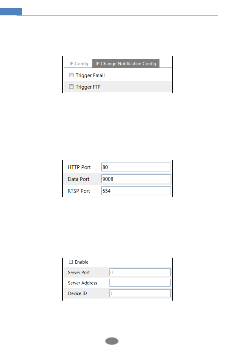
If you check “Obtain an IP address automatically”, the IP address may be changed frequently .
Ten you can use the function of IP change notification.
Trigger Email: when the IP address of the device is changed, a new IP address will be sent to the
appointed mailbox automatically
Trigger FTP: when the IP address of the device is changed, a new IP address will be sent to FTP
server.
4.4.2 Port
Go to ConfigNetworkPort. HTTP port, Data port and RTSP port can be set.
HTTP Port: The default HTTP port is 80. It can be changed to any port which is not occupied.
Data Port: The default data port is 9008. Please change it as required.
RTSP Port: The default port is 554. Please change it as required.
4.4.3 Central Server
This function is mainly used for connecting network video management system.
1. Check “Enable”.
2. Check the IP address and port of the transfer media server in the ECMS/NVMS. Then enable
the auto report in the ECMS/NVMS when adding a new device. Next, input the remaining
Table of contents
Other SIBELL Security Camera manuals

SIBELL
SIBELL IPOB-SB4IRZA User manual

SIBELL
SIBELL Vandal proofDom43e Network Camera User manual

SIBELL
SIBELL IPOB-SB2IR User manual

SIBELL
SIBELL IPPTZ-SB3IR20X User manual

SIBELL
SIBELL HDVD-SB2IRZW User manual

SIBELL
SIBELL IPOB-SB4IRZA User manual

SIBELL
SIBELL IPOD-SB4IR28 User manual

SIBELL
SIBELL SB3IREV User manual

SIBELL
SIBELL IPVD-SB4IRZA User manual

SIBELL
SIBELL IPVD-SB5IRVA User manual


