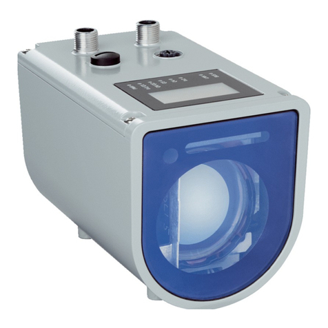
SICK DT1000 User manual

OPERATING INSTRUCTIONS
DT1000 and DL1000
Distance sensor

Described product
DT1000/DL1000
Manufacturer
SICK AG
Erwin-Sick-Str. 1
79183 Waldkirch
Germany
Legal information
This work is protected by copyright. Any rights derived from the copyright shall be
reserved for SICK AG. Reproduction of this document or parts of this document is only
permissible within the limits of the legal determination of Copyright Law. Any modifica‐
tion, abridgment or translation of this document is prohibited without the express writ‐
ten permission of SICK AG.
The trademarks stated in this document are the property of their respective owner.
© SICK AG. All rights reserved.
Original document
This document is an original document of SICK AG.
2O P E R A T I N G I N S T R U C T I O N S | DT1000 and DL1000 8019329/2016-08-05 | SICK
Subject to change without notice

Contents
1 About this document........................................................................ 7
1.1 Information on the operating instructions.............................................. 7
1.2 Explanation of symbols............................................................................ 7
1.3 Scope of delivery...................................................................................... 7
1.4 Customer service...................................................................................... 8
2 Safety information............................................................................ 9
2.1 Intended use............................................................................................. 9
2.2 Incorrect use............................................................................................. 9
2.3 Limitation of liability................................................................................. 9
2.4 Modifications and conversions................................................................ 9
2.5 Requirements for skilled persons and operating personnel................. 9
2.6 Operational safety and particular hazards............................................. 10
2.6.1 Laser radiation......................................................................... 10
2.6.2 Hot surface............................................................................... 11
2.7 Warning signs on the device.................................................................... 11
2.8 UL conformity............................................................................................ 11
2.9 Environmental protection......................................................................... 12
3 Product description........................................................................... 13
3.1 Product characteristics............................................................................. 13
3.2 Design........................................................................................................ 14
3.3 Product ID.................................................................................................. 14
3.4 Switching functions.................................................................................. 15
3.5 Interfaces.................................................................................................. 16
3.5.1 Signal inputs/outputs.............................................................. 16
3.5.2 SSI (synchronous serial interface).......................................... 16
3.5.3 RS-422 interface..................................................................... 18
4 Transport and storage....................................................................... 24
4.1 Transport................................................................................................... 24
4.2 Unpacking.................................................................................................. 24
4.3 Transport inspection................................................................................. 24
4.4 Storage...................................................................................................... 24
5 Mounting............................................................................................. 26
5.1 Mounting procedure................................................................................. 26
5.2 Mounting instructions.............................................................................. 26
5.3 Select and mount the reflector (DL1000 only)....................................... 28
5.4 Placement of multiple distance sensors................................................. 29
5.5 Mounting the alignment bracket and distance sensor.......................... 30
5.6 Aligning distance sensor.......................................................................... 32
6 Electrical installation........................................................................ 34
6.1 Safety......................................................................................................... 34
CONTENTS
8019329/2016-08-05 | SICK O P E R A T I N G I N S T R U C T I O N S | DT1000 and DL1000 3
Subject to change without notice

6.2 Wiring notes.............................................................................................. 34
6.2.1 Technical data for electrical installation................................ 34
6.2.2 Digital outputs.......................................................................... 35
6.2.3 Analog output........................................................................... 36
6.3 Connecting the device electrically........................................................... 37
6.3.1 Pin assignment........................................................................ 38
7 Operation............................................................................................ 39
7.1 Operating concept.................................................................................... 39
7.1.1 Main display level.................................................................... 39
7.1.2 Menu groups............................................................................ 39
7.1.3 Menu items.............................................................................. 40
7.1.4 Parameter input....................................................................... 40
7.1.5 Selection lists........................................................................... 41
7.2 Standard buttons...................................................................................... 41
7.3 Measured value displays.......................................................................... 42
7.3.1 Distance display....................................................................... 42
7.3.2 Signal level display.................................................................. 42
7.3.3 Temperature display................................................................ 42
7.3.4 Operating time display............................................................. 43
7.3.5 Speed display........................................................................... 43
7.4 Overview of parameters........................................................................... 43
7.4.1 Measuring behavior................................................................. 43
7.4.2 IO interfaces............................................................................. 43
7.4.3 Device information................................................................... 44
8 Reference........................................................................................... 45
8.1 Measurement menu group: Defaults...................................................... 45
8.1.1 Measuring mode...................................................................... 45
8.1.2 Defining the measurement cycle time................................... 46
8.1.3 Defining the distance offset................................................... 46
8.1.4 Defining the measuring direction........................................... 47
8.1.5 Configuring the rain and snow filter....................................... 47
8.1.6 Activating/deactivating the fog filter...................................... 48
8.2 Measurement menu group: Advanced settings...................................... 48
8.2.1 Configuring the distance averaging filter............................... 48
8.2.2 Activating/deactivating the Kalman filter.............................. 49
8.2.3 Configuring the speed filter..................................................... 49
8.2.4 Defining the echo selection.................................................... 49
8.2.5 Configuring the distance range.............................................. 50
8.2.6 Configuring the signal level range.......................................... 50
8.2.7 Detecting delay time for "No echo"......................................... 51
8.2.8 Defining substitute values for "No echo"............................... 52
8.2.9 Configuring user-defined substitute values........................... 52
8.2.10 Behaviour on error................................................................... 53
8.3 Interface menu group............................................................................... 53
CONTENTS
4O P E R A T I N G I N S T R U C T I O N S | DT1000 and DL1000 8019329/2016-08-05 | SICK
Subject to change without notice

8.3.1 Defining the switching point for distance value (distance to
object)....................................................................................... 53
8.3.2 Defining the switching hysteresis for the distance value...... 54
8.3.3 Defining the switching point active status for the distance
value......................................................................................... 54
8.3.4 Defining the switching window for the distance value.......... 55
8.3.5 Defining the switching hysteresis for the distance value...... 55
8.3.6 Defining the switching window active status for the dis‐
tance value............................................................................... 56
8.3.7 Defining the switching point for the object speed value....... 56
8.3.8 Defining the switching point hysteresis for the object
speed value.............................................................................. 57
8.3.9 Defining the monitoring direction for the object speed
value......................................................................................... 57
8.3.10 Defining the switching point active status for the object
speed value.............................................................................. 58
8.3.11 Assigning a switching event to the service functions............ 58
8.3.12 Defining the active status for service functions.................... 59
8.3.13 Configuring the QA analog output.......................................... 60
8.3.14 Configuring the switching input.............................................. 60
8.3.15 Defining the active status for digital input............................. 61
8.4 Device menu group................................................................................... 61
8.4.1 Switching the laser on and off................................................ 61
8.4.2 Configuring the heater............................................................. 61
8.4.3 Defining the language............................................................. 62
8.4.4 Defining units of measure....................................................... 62
8.4.5 Adjusting the display contrast................................................. 62
8.4.6 Adjusting the display brightness............................................. 63
8.4.7 Defining the display orientation.............................................. 63
8.5 Communication menu group................................................................... 63
8.5.1 Configuring the serial interface.............................................. 63
8.5.2 Defining the RS-422 data transmission rate......................... 64
8.5.3 Defining the RS-422 data format........................................... 64
8.5.4 Setting the continuous RS-422 output.................................. 65
8.5.5 Defining the RS-422 output cycle time.................................. 66
8.5.6 Defining the RS-422 data protocol......................................... 66
8.5.7 Defining the distance value resolution for the RS-422 data
transfer..................................................................................... 67
8.5.8 Defining the speed value resolution for the RS-422 data
transfer..................................................................................... 67
8.5.9 Defining SSI coding................................................................. 67
8.5.10 Defining the distance value resolution for the SSI data
transfer..................................................................................... 68
8.5.11 Defining the IP addressing mode........................................... 68
8.5.12 Entering an IP address............................................................ 69
8.5.13 Entering a subnet mask.......................................................... 69
8.5.14 Entering a gateway address.................................................... 69
CONTENTS
8019329/2016-08-05 | SICK O P E R A T I N G I N S T R U C T I O N S | DT1000 and DL1000 5
Subject to change without notice
8.5.15 Displaying a MAC address....................................................... 70
8.5.16 Activating DHCP and displaying information.......................... 70
8.6 Info menu group....................................................................................... 70
8.6.1 Retrieving firmware information............................................. 70
8.6.2 Retrieving hardware information............................................ 70
8.6.3 Retrieving the counter readings of switching events............ 71
8.6.4 Deleting the counter readings of switching events............... 71
8.7 Menu tree overview.................................................................................. 71
8.7.1 Main menu............................................................................... 72
8.7.2 Measurement menu group: Defaults..................................... 72
8.7.3 Measurement menu group: Advanced settings..................... 73
8.7.4 IO interface menu group: Digital input In1............................. 74
8.7.5 IO interface menu group: Digital output Q1........................... 75
8.7.6 IO interface menu group: Digital output Q2........................... 76
8.7.7 IO interface menu group: Analog output QA.......................... 77
8.7.8 IO interface menu group: Digital output Q3........................... 78
8.7.9 IO interface menu group: Digital output Q4........................... 79
8.7.10 IO interface menu group: Digital input In2............................. 80
8.7.11 Device menu group.................................................................. 81
8.7.12 Communication menu group.................................................. 82
8.7.13 Info menu group...................................................................... 83
9 Maintenance...................................................................................... 84
9.1 Cleaning..................................................................................................... 84
9.2 Maintenance............................................................................................. 84
10 Troubleshooting................................................................................. 85
10.1 Information for the service case.............................................................. 87
10.2 Returns...................................................................................................... 87
10.3 Repairs...................................................................................................... 87
10.4 Disposal..................................................................................................... 87
11 Technical data.................................................................................... 88
11.1 Performance............................................................................................. 88
11.1.1 .................................................................................................. 89
11.1.2 .................................................................................................. 90
11.2 Interfaces.................................................................................................. 94
11.3 Mechanics/electronics............................................................................. 95
11.4 Ambient data............................................................................................. 95
11.5 Classifications........................................................................................... 95
11.6 Dimensional drawings.............................................................................. 96
11.7 EU declaration of conformity.................................................................... 98
12 Accessories........................................................................................ 99
12.1 Accessories............................................................................................... 99
CONTENTS
6O P E R A T I N G I N S T R U C T I O N S | DT1000 and DL1000 8019329/2016-08-05 | SICK
Subject to change without notice

1 About this document
1.1 Information on the operating instructions
These operating instructions provide important information on how to handle the
Dx1000 product from SICK AG. Adherence to all the specified safety notes and guide‐
lines is a prerequisite for working safely. You must also comply with any local work
safety regulations and general safety specifications applicable to the use of the prod‐
uct.
Ensure that you read through these operating instructions carefully before starting any
work. They constitute an integral part of the product and should be stored in the direct
vicinity of the product so they remain accessible to personnel at all times. If the product
is passed on to a third party, these operating instructions should be handed over with
it.
These operating instructions do not provide information on operating the machine in
which the product is integrated. For information about this, refer to the operating
instructions of the particular machine.
1.2 Explanation of symbols
Warnings in these operating instructions are indicated by symbols. The warnings are
introduced by signal words that indicate the extent of the danger. These warnings must
be observed at all times and care must be taken to avoid accidents, personal injury,
and material damage.
DANGER
… indicates a situation of imminent danger, which will lead to a fatality or serious inju‐
ries if not prevented.
WARNING
… indicates a potentially dangerous situation, which may lead to a fatality or serious
injuries if not prevented.
CAUTION
… indicates a potentially dangerous situation, which may lead to minor/slight injuries if
not prevented.
NOTICE
… indicates a potentially harmful situation, which may lead to material damage if not
prevented.
NOTE
… highlights useful tips and recommendations as well as information for efficient and
trouble-free operation.
1.3 Scope of delivery
Included with delivery:
■Distance sensor
■Optional: Accessories
Supplied documentation:
ABOUT THIS DOCUMENT 1
8019329/2016-08-05 | SICK O P E R A T I N G I N S T R U C T I O N S | DT1000 and DL1000 7
Subject to change without notice

■SafetyNotes
NOTE
All available documentation can be found online at
bwww.sick.com/Dx1000
1.4 Customer service
If you require any technical information, our customer service department will be happy
to help. To find your agency, see the final page of this document.
NOTE
Before calling, make a note of all type label data such as type code, serial number, etc.
to ensure faster processing.
1 ABOUT THIS DOCUMENT
8O P E R A T I N G I N S T R U C T I O N S | DT1000 and DL1000 8019329/2016-08-05 | SICK
Subject to change without notice

2 Safety information
2.1 Intended use
The distance sensor Dx1000 is a photoelectric measuring device and is used for opti‐
cal, non-contact distance measurement of objects.
The distance sensor is used for the non-contact detection of distances between the dis‐
tance sensor and an object (DT1000 product variant) or a suitable reflector (DL1000
product variant). The required optical properties the object or reflector that will be
detected are specified in the technical data section of this document.
SICK AG assumes no liability for losses or damage arising from the use of the product,
either directly or indirectly. This applies in particular to use of the product that does not
conform to its intended purpose and is not described in this documentation.
2.2 Incorrect use
The Dx1000 distance sensors do not constitute safety components according to the EC
Machinery Directive (2006/42/EC). The distance sensors must not be used in explo‐
sion-hazardous areas. Any other use that is not described as a correct use is prohibited.
Any use of accessories not specifically approved by SICK AG is done at your own risk.
WARNING
Danger due to improper use!
Any incorrect use can result in dangerous situations.
Therefore, take note of the following information:
■Dx1000 Use only in accordance with the intended use.
■All information in these operating instructions must be strictly complied with.
2.3 Limitation of liability
Applicable standards and regulations, the latest state of technological development
and many years of knowledge and experience have all been taken into account when
assembling the data and information contained in these operating instructions. The
manufacturer accepts no liability for damage caused by:
■Failing to observe the operating instructions
■Incorrect use
■Use by untrained personnel
■Unauthorized conversions
■Technical modifications
■Use of unauthorized spare parts, consumables and accessories
With special variants, where optional extras have been ordered, or owing to the latest
technical changes, the actual scope of delivery may vary from the features and illustra‐
tions shown here.
2.4 Modifications and conversions
Modifications and conversions to the product and/or the installation may result in
unforeseeable dangers. Before any technical modifications to and expansions of the
product, the prior written approval of the manufacturer must be obtained.
2.5 Requirements for skilled persons and operating personnel
SAFETY INFORMATION 2
8019329/2016-08-05 | SICK O P E R A T I N G I N S T R U C T I O N S | DT1000 and DL1000 9
Subject to change without notice

WARNING
Risk of injury due to insufficient training.
Improper handling may result in considerable personal injury and material damage.
■All work must only ever be carried out by the stipulated persons.
These operating instructions list the training requirements for the various fields of activ‐
ity, as follows:
■Instructed personnel have been given a briefing by the operator about the tasks
assigned to them and about potential dangers arising from improper action.
■Skilled personnel have the specialist training, skills, and experience, as well as
knowledge of the relevant regulations, to be able to perform tasks delegated to
them and to detect any potential dangers independently.
■Electricians have the specialist training, skills, and experience, as well as knowl‐
edge of the relevant standards and provisions to be able to carry out work on elec‐
trical systems and to detect any potential dangers independently. In Germany,
electricians must meet the specifications of the BGV A3 Work Safety Regulations
(e. g. Master Electrician). Other relevant regulations applicable in other countries
must be observed.
2.6 Operational safety and particular hazards
Please observe the safety notes and the warnings listed here and in other chapters of
these operating instructions to reduce the possibility of risks to health and avoid dan‐
gerous situations.
2.6.1 Laser radiation
The device is equipped with two laser sources:
■Measurement laser (not visible to the human eye)
CAUTION
Laser beam class 1 (invisible, infrared)!
The accessible beam does not represent a hazard even if you view it directly for a
long period of time (base period of 100 seconds).
bNever view the laser beam directly with optical instruments (e.g., magnifying
glasses, microscopes, telescopes/binoculars).
bCurrent national regulations regarding laser protection must be complied
with.
■Alignment laser (visible to the human eye)
CAUTION
Laser beam class 1 (visible, red)!
The accessible beam does not represent a hazard even if you view it directly for a
long period of time (base period of 100 seconds). It is not possible to entirely rule
out temporary, disorienting optical effects on the human eye (e.g., dazzle, flash
blindness, afterimages, impairment of color vision), particularly in conditions of
dim lighting.
bNever view the laser beam directly with optical instruments (e.g., magnifying
glasses, microscopes, telescopes/binoculars).
bCurrent national regulations regarding laser protection must be complied
with.
2 SAFETY INFORMATION
10 O P E R A T I N G I N S T R U C T I O N S | DT1000 and DL1000 8019329/2016-08-05 | SICK
Subject to change without notice

Both lasers qualify as class 1 lasers based on the IEC 60825-1: 2014 standard
(Safety of laser products - Part 1: Equipment classification and requirements, Edi‐
tion 3). The requirements for qualifying as a class 1 laser are met even if both
lasers are operated simultaneously.
CAUTION
Laser radiation!
Improper use can lead to hazardous radiation.
bDo not open the device.
bObserve the applicable laser safety regulations in accordance with IEC
60825-1.
2.6.2 Hot surface
CAUTION
Hot surface!
The device is equipped with a heated front screen. The front screen can become hot
while using the heater.
bDo not touch the front screen while using the heater.
2.7 Warning signs on the device
A visible red laser and an invisible infra-red laser is installed in the device. This combi‐
nation corresponds with laser class 1. The housing is labeled with a warning sign.
LASER
1
Figure 1: Warning sign on the device: LASER RADIATION: laser class 1
The device is equipped with a heated front screen. The housing is labeled with a warn‐
ing sign.
Figure 2: Warning sign on the device: HOT SURFACE
2.8 UL conformity
NFPA79 applications only. Adapters including field wiring cables are available.
For more information visit:
bwww.sick.com/Dx1000
CAUTION
Using control elements or settings or executing procedures other than those specified
in this document may result in dangerous exposure to radiation.
SAFETY INFORMATION 2
8019329/2016-08-05 | SICK O P E R A T I N G I N S T R U C T I O N S | DT1000 and DL1000 11
Subject to change without notice

2.9 Environmental protection
ATTENTION
Danger to the environment due to improper disposal of the product!
Disposing of the product improperly may cause damage to the environment.
Therefore, take note of the following information:
bAlways observe the valid regulations on environmental protection.
bFollowing correct disassembly, pass on any disassembled components for reuse.
bSeparate the recyclable materials by type and place them in recycling containers.
2 SAFETY INFORMATION
12 O P E R A T I N G I N S T R U C T I O N S | DT1000 and DL1000 8019329/2016-08-05 | SICK
Subject to change without notice

3 Product description
3.1 Product characteristics
The distance sensor consists of the optics, a sender/receiver unit and an evaluation
unit.
The device emits invisible, infrared laser beam pulses. The receiver receives the
reflected light from an object or a reflector. The evaluation electronics evaluate the dis‐
tance between the sensor and reflector/object using time-of-flight measurement.
The device supports two measuring modes.
•Axial object tracking: Reflector/object move along the laser beam.
•Lateral entry of the object: Reflector/object move perpendicular to the laser beam.
Parameter presettings simplify device configuration for the respective measuring mode.
The object distance and speed (can be configured) determined is transmitted over the
serial interface (switchable: RS-422/SSI). The analog signal output converts the dis‐
tance value into a 4 mA to 20 mA current output signal proportional to the distance.
Digital switching outputs can be used to monitor when configured thresholds/distance
values have been reached. The “Distance to the object” and “Window” switching func‐
tions are supported for doing so. In addition, digital switching outputs can monitor
when configured thresholds have been reached and thereby the speed of the measur‐
ing object to the distance sensor.
A visible alignment laser facilitates installation/alignment of the device with the reflec‐
tor/object.
The measurement technology is designed for indoor and outdoor applications. For such
applications, the device must be protected from environmental factors. Measured dis‐
tance values can be visualized and parameter settings can be made using the graphi‐
cal touch-display. Alternatively, the device can be configured using the SOPAS ET user
interface (PC) (via Ethernet and a web server). For more information visit:
•www.sick.com/SOPAS_ET
PRODUCT DESCRIPTION 3
8019329/2016-08-05 | SICK O P E R A T I N G I N S T R U C T I O N S | DT1000 and DL1000 13
Subject to change without notice

3.2 Design
1
6
ß
9
7
8
2
2
3
3
3
4
3
4
3
3
3
5
1
2
3
4
Figure 3: Dx1000 design
1M5 threaded mounting hole
2Distance measurement zero point
3Mounting points for the alignment bracket (accessory)
4Pressure compensation element
5Touch display
6Electrical connection:
1 Power/RS-422/SSI
2 Auxilliary
3 not assigned, do not remove (glued) protection cap!
4 Ethernet
7Status display
8Measurement laser optical axis
9Receiver optical axis
Alignment laser optical axis
3.3 Product ID
Type label
The following information can be read off the device from the type label:
3 PRODUCT DESCRIPTION
14 O P E R A T I N G I N S T R U C T I O N S | DT1000 and DL1000 8019329/2016-08-05 | SICK
Subject to change without notice

RS-422
IND. CONT. EQ.
4R97
SICK AG
D-79183 Waldkirch
Made in Germany
February 2016
MAC 00:06:77:AC:2E:08
Serial no. 1608 1234
DC 18...30 V class 2
Qx < 100 mA / > 30 V
Power cons. max. 17 W
Ambient max. +55 °C
Enclosure type 3
DT1000-S11101S01
Part no. 1075436
Power/RS-422/SSI
Ethernet Auxiliary
235
7
4
8
9
àß
á
ã
â
6
LASER
1
å
1
Figure 4: Dx1000 type label (example)
1RCM marking of conformity
2EU marking of conformity
32D code with part and serial number
4Month and year of manufacture
5MAC address
6Serial number
7Pin assignment connection 1
8Pin assignment connection 2
9Pin assignment connection 4
Electrical data and environmental information
UL safety mark
Protection class
Warning signs
Interfaces
Part number
Type code
Device display
The following information can be called up using the info menu on the device display:
•Type code
•Part number, serial number
•Interface version, firmware verification, firmware creation date
•Hardware version
3.4 Switching functions
Switching
function
Output state Voltage at Qi at High active status Voltage at Qi at Low active status
Distance
to object
Hysteresis
Inactive
Active
Output value
distance
Switching
state
SP
Hysteresis
Output value
distance
SP
Voltage
High
Low
Output value
distance
SP
Voltage
High
Low
Hysteresis
Table 1: Overview of switching functions
PRODUCT DESCRIPTION 3
8019329/2016-08-05 | SICK O P E R A T I N G I N S T R U C T I O N S | DT1000 and DL1000 15
Subject to change without notice
Switching
function
Output state Voltage at Qi at High active status Voltage at Qi at Low active status
Window
Inactive
Active
SP1
Hysteresis
Output value
distance
Switching
state
SP2
Hysteresis
SP1
Hysteresis
Output value
distance
SP2
Hysteresis
Voltage
High
Low
SP1
Hysteresis
Output value
distance
SP2
Hysteresis
Voltage
High
Low
Object
speed
Inactive
Active
Absolute value of
output value speed
Switching
state
SP
Hysteresis
Absolute value of
output value speed
SP
Voltage
High
Low
Hysteresis
Absolute value of
output value speed
SP
Voltage
High
Low
Hysteresis
Table 1: Overview of switching functions
3.5 Interfaces
3.5.1 Signal inputs/outputs
Signal Type Designation
1 Switchable: digital input, digital output In1 / Q1
2 Switchable: analog output, digital output QA / Q2
3 Digital output Q3
4 Digital output Q4
5 Digital input In2
Table 2: Overview of input/output signals
3.5.2 SSI (synchronous serial interface)
The SSI makes it possible to receive absolute information about the position using
serial data transfer. Cycles and data are transferred over the interface. The data is
transferred upon request from the control system. The cycle time and transmission rate
can be adjusted in wide limits. For this purpose, the connected control unit applies a
pulse sequence to the receiving input of the measuring device. At each positive pulse
edge, a data bit is pushed onto the measuring device's transmission line. This starts
with the highest-value bit. There is a pause of at least 30 µs between two pulse
sequences. The bit pulse is between 70 kHz and 500 kHz and is dependent on the
length of cable, see "Wiring notes", page 34.
3 PRODUCT DESCRIPTION
16 O P E R A T I N G I N S T R U C T I O N S | DT1000 and DL1000 8019329/2016-08-05 | SICK
Subject to change without notice
1 2 3 4
T
tv tm
Tp
Gn G1Gn-
1G0
m
Clock
Monoflop P/S
Data serial
Data parallel
Figure 5: Pulse diagram
Gn Most significant bit in the Gray code
G0 Least significant bit in the Gray code
m Stored parallel information
tm Monoflop time 20 µs
tv Delay time: First clock max. 540 ns, all further clocks max. 360 ns
T Period duration of a clock signal
Tp Clock pause
MSB LSB
Bit23 Bit22 Bit21 Bit20 Bit19 Bit18 ... Bit6 Bit5 Bit4 Bit3 Bit2 Bit1 Bit0
M24*M23 M22 M21 M20 M19 ... M7 M6 M5 M4 M3 M2 M1
Table 3: SSI protocol (data format) Gry24 and Bin24: 24 data bit Gray code/binary code
*M = Measured value bit
MSB LSB
Bit24 Bit23 Bit22 Bit21 Bit20 Bit19 ... Bit6 Bit5 Bit4 Bit3 Bit2 Bit1 Bit0
M241M23 M22 M21 M20 M19 ... M6 M5 M4 M3 M2 M1 S12
DE, AE3
Table 4: SSI protocol (data format) Gry24E and Bin24E: 24 data bit Gray code/binary code + 1 binary error bit (LSB)
1M = Measured value bit
2S = Status bit
3DE = Device error, AE = Application error
MSB LSB
Bit31 Bit30 Bit29 Bit28 ... Bit11 Bit10 Bit9 Bit8 Bit7 Bit6 Bit5 Bit4 Bit3 Bit2 Bit1 Bit0
M241M23 M22 M21 ... M4 M3 M2 M1 S82S7 S6 S5 S4 S3 S2 S1
DE3AE4DW5AW6Q4 Q3 Q2 In1/Q1
Table 5: SSI protocol (data format) Gry24+8 and Bin24+8: 32 data bit Gray code/binary code
1M = Measured value bit
2S = Status bit
3DE = Device error
4AE = Application error
5DW = Device warning
6AW = Application warning
PRODUCT DESCRIPTION 3
8019329/2016-08-05 | SICK O P E R A T I N G I N S T R U C T I O N S | DT1000 and DL1000 17
Subject to change without notice
MSB LSB
Bit24 Bit23 Bit22 Bit21 Bit20 Bit19 ... Bit6 Bit5 Bit4 Bit3 Bit2 Bit1 Bit0
M25*M24 M23 M22 M21 M20 ... M7 M6 M5 M4 M3 M2 M1
Table 6: SSI protocol (data format) Gry25 and Bin25: 25 data bit Gray code/binary code
*M = Measured value bit
3.5.3 RS-422 interface
You can read out the measured data and the defined operating data as well as change
the parameters using the distance measuring device's RS-422 serial interface. All data
is transmitted as ASCII characters. Measured data such as distance or combined dis‐
tance/speed values and operating data such as the internal temperature are transfer‐
red upon request. Distance values, the combined distance, speed and service values
can be transferred in a continuous data stream.
3.5.3.1 General Information
The serial interface makes it possible to read out measured values and other defined
operating data and defined parameter data on the device. All data is transmitted as
ASCII characters. The syntax of the communication protocol corresponds to the specifi‐
cation of the SOPAS CoLa-A protocol.
The device can be configured so that distance values and selected combined data can
be output in a continuous data stream. Two different protocol types are available for
continuous output. "CRLF" and "STX/ETX". The syntax of this continuous data is based
on SICK products DL100 and DME5000.
The factory presetting of the Dx1000 is:
•Protocol type: CRLF
•Output of measured values: on request
•Baud rate: 115K2, 8n1 with a resolution of 1 mm
3.5.3.2 Protocol type and data for continuous output
A non-volatile configuration in the output mode and the selected protocol type is possi‐
ble. Depending on the protocol selected, the Dx1000 transmits a continuous data
stream, as shown below:
•CRLF protocol type:
The data fields are completed by the non-displayable ASCII characters <CR>
(0x38) and <LF> (0x35). These also act as separators in the data stream.
•STX/ETX protocol type:
The data fields are integrated in the non-displayable ASCII characters <STX>
(0x02) and <ETX> (0x03). The first four characters of the data field have a con‐
stant pre-assignment for compatibility reasons.
Protocol type Protocol structure (example) Output mode
CRLF <Data field><CR><LF> Continuous
STX/ETX <STX><data
field><ETX>
Continuous
Table 7: Protocol structure and output mode
The following data can be output via the continuous output:
3 PRODUCT DESCRIPTION
18 O P E R A T I N G I N S T R U C T I O N S | DT1000 and DL1000 8019329/2016-08-05 | SICK
Subject to change without notice
Designation CRLF protocol structure STX/ETX protocol structure
Distance (resolu‐
tion according to
setting)
<[sign]><7*[0...9]>
Example:
+0001800<CR><LF>
<‘0322‘><[sign]><7*[0...9
]>
Example:
<STX>0322+0001800<ETX>
Distance + speed
(distance +
speed resolution
according to set‐
ting)
<[sign]><7*[0...9]><[sign
]><5*[0....9]>
Example:
+0001800+0200<CR><LF>
<’8124’><[sign]><7*[0...9
]><[sign]><5*[0....9]>
Example:
<STX>0324+0001800+0200<ETX
>
Distance + status
service string is
coded in hexa‐
decimals: 32 bit
(8 ASCII charac‐
ters)
<[sign]><7*[0...9]><_><8*[
0...F]>
Example:
+0001800_00002345<CR><LF>
<[sign]><7*[0...9]>
Example:
<STX>0321+0001800_00002345
<ETX>
Distance + signal
level (RSSI)
<[sign]><7*[0...9]><_><5*[
0...9]>
Example:
+0001800_02300<CR><LF>
0323<[sign]><7*[0...9]<_><
5*[0...9]>
Example:
<STX>0323+0001800_02300<ET
X>
Table 8: Data for continuous output
3.5.3.3 Commands
All varieties and methods which are also accessible via the display can be read, written
or executed via the RS-422- interface in the SOPAS CoLa-A protocol. A selection of com‐
mands is displayed here.
3.5.3.3.1 Setting authorization for parameter change
If parameters are to be changed, the user must activate the access mode ("log in").
Changes become active when the access mode is set back to "Run" ("log out"). Perma‐
nent storage of the changed parameters requires a special command to be executed,
see "Special functions", page 21.
The "Activate access mode" function ends continuous data output. The "Deactivate
access mode" function restarts continuous data output.
Designation Syntax
Activate access mode
--> Response (1 = success)
= "Log in"
sMN SetAccessMode 4 81BE23AA
sAN SetAccessMode <[0…1]>
Deactivate access mode
--> Response (1 = success)
= "Log off"
sMN Run
sAN Run <[0…1]>
Table 9: Syntax: Setting authorization for parameter change
PRODUCT DESCRIPTION 3
8019329/2016-08-05 | SICK O P E R A T I N G I N S T R U C T I O N S | DT1000 and DL1000 19
Subject to change without notice
3.5.3.3.2 Continuous output
Designation Syntax
Define content of continu‐
ous output via the "OC"
parameter
--> Response OK
Output Format Parame‐
ter
OC
(Enum8)
Off 0
Distance 1
Distance + speed 2
Distance + status 3
Distance + RSSI 4
sWN rs422PeriodicOutputContent <OC>
sWA rs422PeriodicOutputContent<[0…1] >
Select STX/ETX protocol
-> Response OK
sWN rs422PeriodicOutputFormat 0
sWA rs422PeriodicOutputFormat
Select CRLF protocol
-> Response OK
sWN rs422PeriodicOutputFormat 1
sWA rs422PeriodicOutputFormat
Set output rate in ms
(coded in hexadecimals,
0…1000 ms, corresponds
to 0…3E8)
sWN rs422PeriodicDuration <[0…3E8]>
sWA rs422PeriodicDuration
Table 10: Syntax: Continuous output
3.5.3.3.3 Data in requirement mode
Designation Syntax
Request distance
-´-> Response
Output is coded in hexa‐
decimals (Dint):
Resolution: 1 mm
Example:
Output 3E8 Corresponds to
1000 mm
sRN Distance
sRA Distance <n*[0...9]>
<STX>sRA Distance 3E8<ETX>
Request speed
--> Response
Output is coded in hexa‐
decimals (Dint):
Resolution: 1 mm/s
Example:
Output 7D0 Corresponds to
2000 mm/s
Output FFFFF830 Corre‐
sponds to -2000 mm/s
sRN Velocity
sRA Velocity <n*[0...9]>
<STX>sRA Velocity 7D0<ETX>
<STX>sRA Velocity FFFFF830<ETX>
Request reception level
(RSSI)
--> Response
Output is coded in hexa‐
decimals (Dint).
Example:
Output 1388 Corresponds
to 5000
sRN RSSI
sRA RSSI <n*[0...9]>
<STX>sRA RSSI 1388<ETX>
Table 11: Syntax: Data in requirement mode
3 PRODUCT DESCRIPTION
20 O P E R A T I N G I N S T R U C T I O N S | DT1000 and DL1000 8019329/2016-08-05 | SICK
Subject to change without notice
Other manuals for DT1000
3
This manual suits for next models
1
Table of contents
Other SICK Accessories manuals

SICK
SICK LD-LRS User manual

SICK
SICK WTB4F User manual

SICK
SICK LMS1104C-111031S01 User manual

SICK
SICK LBV 320 User manual

SICK
SICK WTB4-3 User manual

SICK
SICK MRS1000P User manual

SICK
SICK deTec4 Core User manual

SICK
SICK LFV 200 User manual

SICK
SICK CS81-P3612S02 User manual

SICK
SICK LBV 321 NAMUR User manual

SICK
SICK Inspector I10 User manual

SICK
SICK Profiler 2 User manual

SICK
SICK GLS100 User manual

SICK
SICK TiM781 User manual

SICK
SICK OD7000 Series User manual

SICK
SICK TiM781 User manual

SICK
SICK W4F User manual

SICK
SICK CSS High Speed User manual

SICK
SICK TriSpector1000 User manual

SICK
SICK GLS611 User manual