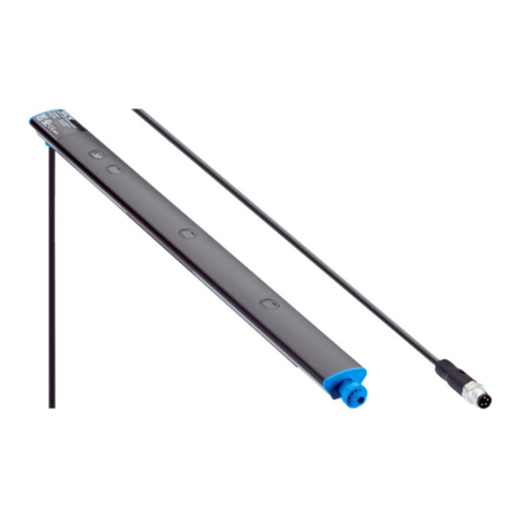
SICK senSe2 User manual

OPERATING INSTRUCTIONS
senSe2
Safety light curtain

Described product
senSe2
Manufacturer
SICK AG
Erwin-Sick-Str. 1
79183 Waldkirch
Germany
Legal information
This work is protected by copyright. Any rights derived from the copyright shall be
reserved for SICK AG. Reproduction of this document or parts of this document is
only permissible within the limits of the legal determination of Copyright Law. Any modi‐
fication, abridgment or translation of this document is prohibited without the express
written permission of SICK AG.
The trademarks stated in this document are the property of their respective owner.
© SICK AG. All rights reserved.
Original document
This document is an original document of SICK AG.
2O P E R A T I N G I N S T R U C T I O N S | senSe2 8027557/2022-11-11 | SICK
Subject to change without notice

Contents
1 About this document........................................................................ 6
1.1 Purpose of this document........................................................................ 6
1.2 Scope......................................................................................................... 6
1.3 Target groups of these operating instructions........................................ 6
1.4 Additional information.............................................................................. 6
1.5 Symbols and document conventions...................................................... 7
2 Safety information............................................................................ 8
2.1 General safety notes................................................................................ 8
2.2 Intended use............................................................................................. 8
2.3 Inappropriate use..................................................................................... 8
2.4 Requirements for the qualification of personnel.................................... 9
3 Product description........................................................................... 10
3.1 Structure and function............................................................................. 10
3.2 Product characteristics............................................................................ 11
3.2.1 Device overview....................................................................... 11
3.2.2 Absence of blind zones........................................................... 11
3.2.3 Automatic calibration of the protective field width................ 11
3.2.4 Alignment aid........................................................................... 11
3.2.5 Status indicators...................................................................... 11
3.3 Example applications............................................................................... 13
4 Project planning................................................................................ 15
4.1 Manufacturer of the machine.................................................................. 15
4.2 Operating entity of the machine.............................................................. 15
4.3 Design........................................................................................................ 15
4.3.1 Scanning range and protective field width............................. 16
4.3.2 Minimum distance from the hazardous point....................... 16
4.3.3 Minimum distance to reflective surfaces............................... 19
4.3.4 Protection against interference from systems in close prox‐
imity to each other................................................................... 20
4.4 Integration in electrical control................................................................ 21
4.4.1 Restart interlock...................................................................... 23
4.4.2 External device monitoring (EDM).......................................... 24
4.4.3 Connection diagrams.............................................................. 25
4.5 Testing plan............................................................................................... 25
4.5.1 Test rod check.......................................................................... 26
4.5.2 Visual check of the machine and the protective device........ 29
5 Mounting............................................................................................. 30
5.1 Unpacking.................................................................................................. 30
5.2 Installation................................................................................................ 30
5.2.1 Mounting the QuickFix bracket............................................... 33
CONTENTS
8027557/2022-11-11 | SICK O P E R A T I N G I N S T R U C T I O N S | senSe2 3
Subject to change without notice

5.2.2 Mounting the FlexFix bracket.................................................. 35
5.2.3 Mounting the Compact FlexFix bracket.................................. 37
5.2.4 Mounting the flat mount bracket............................................ 39
5.2.5 Mounting the swivel mount bracket....................................... 40
5.2.6 Mounting the upgrade bracket............................................... 43
6 Electrical installation........................................................................ 44
6.1 Safety......................................................................................................... 44
6.2 System connection (M12, 5-pin)............................................................. 45
6.3 System connection via connection cable (M12, 5-pin to 8-pin)............ 46
7 Commissioning.................................................................................. 47
7.1 Overview.................................................................................................... 47
7.2 Switching on.............................................................................................. 47
7.3 Sender and receiver alignment................................................................ 47
7.3.1 Aligning the sender and receiver............................................ 48
7.3.2 Alignment with the QuickFix bracket...................................... 49
7.3.3 Alignment with the FlexFix bracket or with the upgrade
bracket...................................................................................... 49
7.3.4 Alignment with the Compact FlexFix bracket......................... 50
7.3.5 Alignment with the swivel mount bracket.............................. 51
7.3.6 Indication of the alignment quality......................................... 52
7.4 Check during commissioning and modifications.................................... 52
8 Operation............................................................................................ 53
8.1 Regular thorough check........................................................................... 53
9 Maintenance...................................................................................... 54
9.1 Regular cleaning....................................................................................... 54
9.2 Regular thorough check........................................................................... 55
10 Troubleshooting................................................................................. 56
10.1 Safety......................................................................................................... 56
10.2 Diagnostic LEDs........................................................................................ 56
10.2.1 Fault indicators........................................................................ 56
11 Decommissioning............................................................................. 58
11.1 Disposal..................................................................................................... 58
12 Technical data.................................................................................... 59
12.1 Data sheet................................................................................................. 59
12.2 Response time.......................................................................................... 61
12.3 Power consumption.................................................................................. 61
12.4 Length of cable......................................................................................... 62
12.5 Table of weights........................................................................................ 62
12.6 Dimensional drawings.............................................................................. 63
13 Ordering information........................................................................ 64
CONTENTS
4O P E R A T I N G I N S T R U C T I O N S | senSe2 8027557/2022-11-11 | SICK
Subject to change without notice

13.1 Scope of delivery....................................................................................... 64
13.2 Ordering information................................................................................. 64
14 Accessories........................................................................................ 65
14.1 Brackets.................................................................................................... 65
14.2 Mounting accessories.............................................................................. 67
14.3 Connectors................................................................................................ 68
14.4 Alignment aid............................................................................................ 69
14.5 Cleaning agent.......................................................................................... 69
14.6 Test rods.................................................................................................... 69
15 Annex.................................................................................................. 70
15.1 Conformities and certificates................................................................... 70
15.1.1 EU declaration of conformity................................................... 70
15.2 Note on standards.................................................................................... 70
15.3 Checklist for initial commissioning and commissioning........................ 71
16 List of figures..................................................................................... 72
17 List of tables....................................................................................... 73
CONTENTS
8027557/2022-11-11 | SICK O P E R A T I N G I N S T R U C T I O N S | senSe2 5
Subject to change without notice
Table of contents
Other SICK Accessories manuals

SICK
SICK PowerProx Micro WTT2SL Series User manual

SICK
SICK WTB4FP MultiSwitch User manual

SICK
SICK KTX Prime KTX-WB9224225AZZZZ User manual

SICK
SICK VISIC100SF User manual

SICK
SICK TiM3 Series User manual

SICK
SICK KTML Series User manual

SICK
SICK WS24-2 Series User manual

SICK
SICK WT18-3 User manual

SICK
SICK WLD26 User manual

SICK
SICK IQ80-50BPP-KC0 User manual

SICK
SICK TiM2 Series User manual

SICK
SICK SureSense HTF18L User manual

SICK
SICK deTec4 Core User manual

SICK
SICK LUT9 User manual

SICK
SICK MPS-G User manual

SICK
SICK SIM2000ST User manual

SICK
SICK PowerProx WTT12L User manual

SICK
SICK SureSense-HTF18 User manual

SICK
SICK KTS Core KTS-WS41141142ZZZZ User manual

SICK
SICK KTS Prime User manual