SICK RAY26 User manual

Described product
RAY26
Manufacturer
SICK AG
Erwin-Sick-Str. 1
79183 Waldkirch
Germany
Legal information
This work is protected by copyright. Any rights derived from the copyright shall be
reserved for SICK AG. Reproduction of this document or parts of this document is
only permissible within the limits of the legal determination of Copyright Law. Any modi‐
fication, abridgment or translation of this document is prohibited without the express
written permission of SICK AG.
The trademarks stated in this document are the property of their respective owner.
© SICK AG. All rights reserved.
Original document
This document is an original document of SICK AG.
2006/42/EC
NO
SAFETY
8022178.19RH 08.01.2021 | SICK
Subject to change without notice 3

Contents
1 General safety notes......................................................................... 5
2 Notes on UL approval........................................................................ 5
3 Intended use...................................................................................... 5
4 Operating and status indicators...................................................... 5
5 Mounting............................................................................................. 6
6 Electrical installation........................................................................ 6
7 Commissioning.................................................................................. 8
7.1 Alignment.................................................................................................. 8
7.2 Check the application conditions............................................................ 12
7.3 Conveyor blanking..................................................................................... 13
8 Process data structure..................................................................... 15
9 Troubleshooting................................................................................. 15
10 Disassembly and disposal............................................................... 16
11 Maintenance...................................................................................... 16
12 Technical data.................................................................................... 17
12.1 Dimensional drawing................................................................................ 18
CONTENTS
48022178.19RH 08.01.2021 | SICK
Subject to change without notice

1 General safety notes
■Read the operating instructions before commissioning.
■
Connection, mounting, and configuration may only be performed by trained
specialists.
■
2006/42/EC
NO
SAFETY
Not a safety component in accordance with the EU Machinery Directive.
■
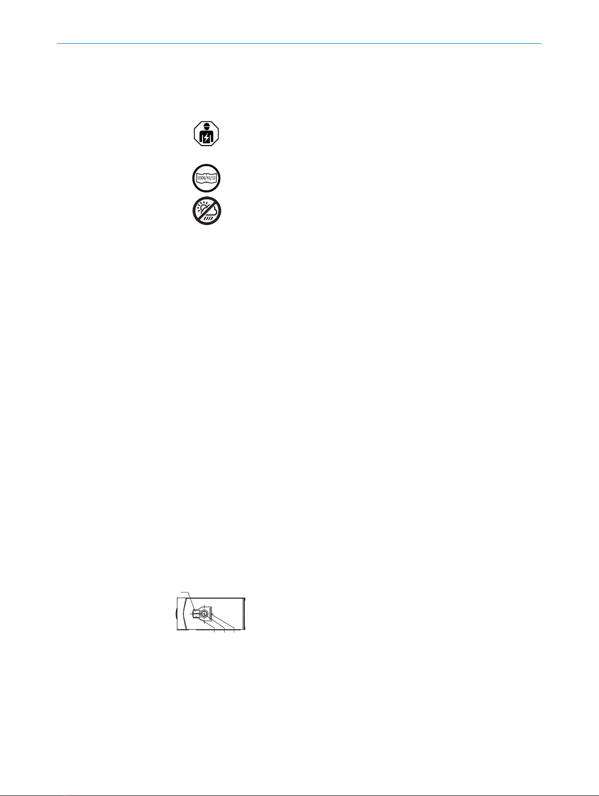
Do not install the sensor at locations that are exposed to direct sunlight
or other weather influences, unless this is expressly permitted in the operating
instructions.
■These operating instructions contain information required during the life cycle of
the sensor.
2 Notes on UL approval
The device shall be supplied from an isolating transformer having a secondary overcur‐
rent protective device that complies with UL 248 to be installed in the field rated either:
a) max 5 amps for voltages 0 ~ 20 V (0 ~ 28.3 V peak), or
b) 100 / Vp for voltages of 20 ~ 30 V (28.3 ~ 42.4 V peak).
Alternatively, they can be supplied from a Class 2 power supply.
UL Environmental Rating: Enclosure type 1
3 Intended use
The RAY26 is an opto-electronic photoelectric retro-reflective sensor (referred to as
“sensor” in the following) for the optical, non-contact detection of objects, animals, and
persons. A reflector is required for this product to function. If the product is used for any
other purpose or modified in any way, any warranty claim against SICK AG shall become
void.
4 Operating and status indicators
1
243
1LED indicator green: supply voltage active
2BluePilot blue: AutoAdapt indicator during run mode
3Teach-in button
4LED indicator yellow: status of received light beam
GENERAL SAFETY NOTES 1
8022178.19RH 08.01.2021 | SICK
Subject to change without notice 5

5 Mounting
Mount the sensor and the reflector using suitable mounting brackets (see the SICK
range of accessories). Align the sensor and reflector with each other.
Note the sensor's maximum permissible tightening torque of 0.65Nm.
NOTE
RAY26P-XXXXX1 (MDO ≥ 1 MM), RAY26P-XXXXX3 (MDO ≥ 3 MM):
Recommended position of installation: between conveyor belts or conveyor rollers
6 Electrical installation
Operation in standard I/O mode:
The sensors must be connected in a voltage-free state (UV = 0 V). The following informa‐
tion must be observed, depending on the connection type:
– Plug connection: note pin assignment
– Cable: wire color
Only apply voltage/switch on the voltage supply (UV > 0 V) once all electrical connec‐
tions have been established.
Operation in IO-Link mode: Connect the device to a suitable IO-Link master and inte‐
grate in the master or control via IODD/function block. The green LED indicator flashes
on the sensor. IODD and function block are available to download from www.sick.com
under the part number.
Explanation of the connection diagram (following tables):
Alarm = alarm output (see table 2 and table 4)
MF = multifunctional, programmable output
n. c. = not connected
QL1/C = switching output, IO-Link communication
5 MOUNTING
68022178.19RH 08.01.2021 | SICK
Subject to change without notice

UB: 10 ... 30 V DC
Table 1: DC
RAY26P-
Push-pull x4162xxxA00 xH162xxxA00 x4161xxxA00 x4161xxxA00
PNP x4862xxxA00 xH862xxxA00 x4861xxxA00 xH861xxxA00
1+ (L+)
2MF
3- (M)
4QL1/C
Default: MF Q Q Q Q
Default: QL1/C Q Q Q Q
12
4 3
1 = BN
2 = WH
3 = BU
4 = BK
0.14 mm2
AWG26
12
4 3
1 = BN
2 = WH
3 = BU
4 = BK
0.14 mm2
AWG26
Table 2: DC
RAY26P-
Push-pull x4165xxxA00 xH165xxxA00 x4163xxxA00 xH163xxxA00
PNP x4865xxxA00 xH865xxxA00 x4863xxxA00 xH863xxxA00
1+ (L+)
2MF
3- (M)
4QL1/C
Default: MF Alarm Alarm Alarm Alarm
Default: QL1/C Q Q Q Q
12
4 3
1 = BN
2 = WH
3 = BU
4 = BK
0.14 mm2
AWG26
12
4 3
1 = BN
2 = WH
3 = BU
4 = BK
0.14 mm2
AWG26
ELECTRICAL INSTALLATION 6
8022178.19RH 08.01.2021 | SICK
Subject to change without notice 7

Table 3: Push-pull, PNP, NPN
Push-pull
PNP
NPN
+ (L+)
Q ≤ 100 mA
‒ (M)
Push-pull
PNP
NPN
+ (L+)
Q ≤ 100 mA
‒ (M)
Push-pull
PNP
NPN
+ (L+)
Q≤ 100 mA
‒ (M)
Push-pull
PNP
NPN
+ (L+)
Q≤ 100 mA
‒ (M)
Table 4: Alarm
Alarm (≤ 100 mA)
+ (L+)
Alarm
‒ (M)
+ (L+)
Alarm
‒ (M)
7 Commissioning
7.1 Alignment
7 COMMISSIONING
88022178.19RH 08.01.2021 | SICK
Subject to change without notice

Figure 1: Alignment
NOTE
The adjustment of the height (1) should be separated from the adjustment of the angle
(2).
Figure 2: (1)
Figure 3: (2)
COMMISSIONING 7
8022178.19RH 08.01.2021 | SICK
Subject to change without notice 9

1 Alignment of the light band in the gap between two conveyor belts
2 a) Alignment of the light band above the conveyor belt.
The light band has to be positioned parallel to the conveyor belt.
3 mm 0 mm
12
1 RAY26P-xxxxx1 / RAY26P-xxxxx3 / RAY26P-xxxxx5 / RAY26P-xxxxx9
2 RAY26P-xxxxxA
b) Take a metal plate and position it in front of the reflector. Rotate the sensor up
a little. The light band is approx. 20 mm above the conveyor belt.
7 COMMISSIONING
10 8022178.19RH 08.01.2021 | SICK
Subject to change without notice

1
1 = metal plate
c) Rotate the sensor down a little until the lower edge of the light band will hit the
conveyor belt (see light band on metal plate). Then fix the housing at the bracket.
The light band may not be moved further into the conveyor.
1
1
d) Remove the metal plate from the light band and teach the RAY26, after which it
is ready for operation.
NOTE
Tip:
Control of the setting: Switch on conveyor belt. In "idling mode" (conveyor belt moves
without material to be conveyed), the sensor must not switch. Switch on conveyor belt.
Place the goods in succession on the conveyor belt edges and in the middle on the belt
to check the reliable detection in three places.
COMMISSIONING 7
8022178.19RH 08.01.2021 | SICK
Subject to change without notice 11

NOTE
Video of commissioning:
7.2 Check the application conditions
Sensing range
Reconcile the distance between the sensor and the reflector with the corresponding
diagram see figure 4, page 12.
3
2
1
4
Figure 4: sensing range areas
Table 5: Definition sensing range
12 3 4
RAY26P-xxxxx1 PL80A 0 ... 1.5 m ≥ 1 mmA
RAY26P-xxxxx3 PL80A 0 ... 2 m ≥ 3 mmB
0 ... 3 m ≥ 5 mmB
0 ... 4.5 m ≥ 10 mmB
RAY26P-xxxxx5 PL80A 0 ... 3 m ≥ 5 mmA
RAY26P-xxxxx9 PL80A 0 ... 4.5 m ≥ 10 mmA
RAY26P-xxxxxA PL80A 0 ... 4.5 m C
3Sensing range, on reflector 2
4Minimum detectable object (MDO)
AMDO is fix
BMDO ≥ 3 mm, ≥ 5 mm, ≥ 10 mm:
can be selected via IO-Link
CFactory setting see data sheet
MDO ≥ 10 mm, ≥ 15 mm, ≥ 20 mm, ≥ 25 mm, ≥ 30 mm; are selectable via IO-Link
Table 6: Sensing ranges on reflectors
1,5
0
1,5
0
1,5
0
2
3
4
11,5
0
0
Sensing range
4
(13.12)
Distance in m (feet)
1
(3.28)
3
(9.84)
5
(16.40)
2
(6.56)
Figure 5: RAY26P-xxxxx1
1PL80A
2PL40A
3PL30A
4P250F
0
0
2
0
2
0
2
0
Sensing range
4
(13.12)
Distance in m (feet)
1
(3.28)
3
(9.84)
5
(16.40)
2
(6.56)
1
2
3
Figure 6: RAY26P-xxxxx3
1PL80A
2PL81
3PL100
7 COMMISSIONING
12 8022178.19RH 08.01.2021 | SICK
Subject to change without notice

0
0
3
0
2
0
2
0
Sensing range
4
(13.12)
Distance in m (feet)
1
(3.28)
3
(9.84)
5
(16.40)
2
(6.56)
1
2
3
Figure 7: RAY26P-xxxxx5
1PL80A
2PL81
3PL100
0
0
4.5
0
3
0
3
0
Sensing range
4
(13.12)
Distance in m (feet)
1
(3.28)
3
(9.84)
5
(16.40)
2
(6.56)
1
2
3
Figure 8: RAY26P-xxxxx9, RAY26P-xxxxxA
1PL80A
2PL81
3PL100
Minimum detectable object (MDO):
4
1
4
1
4
1
Sensing range setting:
1...3 sec.
1
2
7.3 Conveyor blanking
Conveyor blanking, manual
RAY26P-xxxxx3
COMMISSIONING 7
8022178.19RH 08.01.2021 | SICK
Subject to change without notice 13

RAY26P-xxxxx5
RAY26P-xxxxx9
1. Place an object A with the corresponding height to be blanked (e.g. 3 mm) in the
light band in front of the RAY26.
A
2. Teach RAY26 and it is ready for use.
3. Remove the object from the light band.
This area (B = object height A) is now blanked for detection.
If the conveyor belt moves a little bit up, it is not detected.
An object must now be e.g. approx. 8 mm high so that it can be detected by
RAY26P-xxxxx5 (MDO: 5 mm). If the RAY26 is re-teached without object A into
the light band, then the blanked area is no longer present and is available for
detection again.
B
Conveyor blanking via IO-Link
RAY26P-xxxxx3
The conveyor blanking allows a stepwise inactivation of the detection area (A = approx.
1 mm for each level) just above the conveyor belt. Thereby influences of the conveyor
belt (which causes false signals of the sensor) can be suppressed. The setting of the
conveyor blanking can be done via IO-Link with the index 238.
After setting the sensor has to be taught again (index 2, value 65).
Table 7: Index 238
ISDU
Name Data
type Length Access Default
value Value/RangeIndex Sub-
Index
DEC HEX
238 0xE
E- Conveyor blanking Uint 8 Bit rw 0
0 = Deactivated
1 = Level 1
2 = Level 2
3 = Level 3
4 = Level 4
7 COMMISSIONING
14 8022178.19RH 08.01.2021 | SICK
Subject to change without notice

A
1
Figure 9: A = Level 1
A
1
Figure 10: A = Level 2
A
1
Figure 11: A = Level 3
A
1
Figure 12: A = Level 4
1Conveyor belt
NOTE
You can find videos on the Reflex Array product page www.sick.com/reflex-array under
"Videos".
8 Process data structure
RAY26P-xxxxxxxx A00
IO-Link V1.1
Process data 2 byte
Byte 0: bits 15... 8
Byte 1: bits 7... 0
Bit 0 / Data type QL1 / Boolean
Bit 1 / Data type QL2 / Boolean
Bit 2 ... 15 / Description / Data type [empty]
9 Troubleshooting
The Troubleshooting table indicates measures to be taken if the sensor stops working.
LED indicator/fault pattern Cause Measures
Green LED flashes IO-Link communication None
Switching outputs do not
behave in accordance with
see table 3, page 8 and see
table 4, page 8
a) IO-Link communication
b) Change of the configuration
c) Short-circuit
a) None
b) Adjustment of the configu‐
ration
c) Check electrical connec‐
tions
The blue LEDs are very close
together
Front screen and/or reflector
is contaminated.
Cleaning of the optical sur‐
faces (sensor and reflector).
Yellow LED flashes Distance between sensor and
reflector is too large / light
band is not completely aligned
to the reflector / reflector is
not suitable / front screen
and/or reflector is contami‐
nated
Check sensing range / check
alignment / SICK reflector is
recommended / Cleaning of
the optical surfaces (sensor
and reflector)
PROCESS DATA STRUCTURE 8
8022178.19RH 08.01.2021 | SICK
Subject to change without notice 15

LED indicator/fault pattern Cause Measures
Yellow LED does not light up
even though the light band is
aligned to the reflector and
there is no object in the path
of the beam
No voltage or voltage below
the limit values
Check the power supply,
check all electrical connec‐
tions (cables and plug connec‐
tions)
Voltage interruptions Ensure there is a stable power
supply without interruptions
Sensor is faulty If the power supply is OK,
replace the sensor
10 Disassembly and disposal
The sensor must be disposed of according to the applicable country-specific regula‐
tions. Efforts should be made during the disposal process to recycle the constituent
materials (particularly precious metals).
NOTE
Disposal of batteries, electric and electronic devices
•According to international directives, batteries, accumulators and electrical or
electronic devices must not be disposed of in general waste.
•The owner is obliged by law to return this devices at the end of their life to the
respective public collection points.
•
WEEE: This symbol on the product, its package or in this document,
indicates that a product is subject to these regulations.
11 Maintenance
SICK sensors are maintenance-free.
We recommend doing the following regularly:
•Clean the external lens surfaces
•Check the screw connections and plug-in connections
No modifications may be made to devices.
Subject to change without notice. Specified product properties and technical data are
not written guarantees.
10 DISASSEMBLY AND DISPOSAL
16 8022178.19RH 08.01.2021 | SICK
Subject to change without notice

12 Technical data
RAY26P-xxxxx1 RAY26P-xxxxx3 RAY26P-xxxxx5 RAY26P-xxxxx9 RAY26P-xxxxxA
Sensing range max.
(with reflector PL80A)
0 ... 1.5 m 0 ... 4.5 m 0 ... 3 m 0 ... 4.5 m 0 ... 4.5 m
Light band dimen‐
sions / distance
approx.
20 mm x 9 mm (1
m)
55 mm x 9 mm (1m)
Minimum detectable
object (MDO)
≥ 1 mm ≥ 3 mm, 5 mm or
10 mm1)
≥ 5 mm ≥ 10 mm ≥ 10 mm, 15 mm,
20 mm, 25 mm or
30 mm2)
Minimum distance
between sensor and
reflector
0 mm
Supply voltage UB10 ... 30 V DC
Current consumption ≤ 25 mA3), < 50 mA4)
Output current Imax. ≤ 100 mA
Communication mode COM2
IO-Link 1.1
Max. response time ≤ 3 ms5) ≤ 500 μs5)
Switching frequency 170 Hz6) 1000 Hz6)
Enclosure rating IP66, IP67
Protection class III
Circuit protection A, B, C, D7)
Ambient operating tem‐
perature
–40 °C ... +60 °C8)9)
1) RAY26P-xxxxx3: sensing range depends on the selected MDO (selectable via IO-Link):
3 mm = 0 ... 2 m
5 mm = 0 ... 3 m
10 mm = 0 ... 4.5 m
2) Factory setting see data sheet, MDO is selectable via IO-Link
3) 16 VDC to 30 VDC, without load
4) 10 VDC to 16 VDC, without load
5) Signal transit time with resistive load in switching mode. Deviating values possible in COM2 mode.
6) With a light/dark ratio of 1:1 in switching mode. Deviating values possible in IO-Link mode.
7) A = UB-connections reverse polarity protected
B = inputs and output reverse-polarity protected
C = Interference suppression
D = outputs overcurrent and short-circuit protected
8) Avoid condensation on the front screen of the sensor and on the reflector.
9) Allowed temperature change after Teach +/- 20 K
TECHNICAL DATA 12
8022178.19RH 08.01.2021 | SICK
Subject to change without notice 17

12.1 Dimensional drawing
Table 8: Dimensional drawing
1
24.6 (0.97)
8(0.31)
6.9 (0.27)
Ø 12.8 (0.50)
55 (2.17)
37.9 (1.49)
9.4 (0.37)
7.2
(0.28)
3
2
2
7.1 (0.28)
8.1 (0.32)
10.8 (0.43)
25 (0.98)
38.9 (1.53)
6.4
(0.25)
48.1 (1.89)
40 (1.57)
44.2 (1.74)
10
(0.39)
Ø 5.2 (0.2)
82.2 (3.24)
70 (2.76)
Ø 5.2 (0.2)
8.1 (0.32)
76.5 (3.01)
82.5 (3.25)
53.4 (2.10)
4
Figure 13: with cable
RAY26P-xxxxx3, RAY26P-xxxxx5, RAY26P-
xxxxx9, RAY26P-xxxxxA
M12
1
3
2
2
7.1 (0.28)
8.1 (0.32)
10.8 (0.43)
25 (0.98)
38.9 (1.53)
6.3 (0.25)
48.1 (1.89)
40 (1.57)
44.2 (1.74)
19.7
(0.78)
Ø 5.2 (0.2)
24.6 (0.97)
8(0.31)
6.9 (0.27)
82.2 (3.24)
70 (2.76)
Ø 5.2 (0.2)
17.1
(0.67)
7.9 (0.31)
76.5 (3.01)
82.5 (3.25)
55 (2.17)
37.9 (1.49)
9.4 (0.37)
53.3 (2.1)
63.9 (2.52)
4
Figure 14: with connector
RAY26P-xxxxx3, RAY26P-xxxxx5, RAY26P-
xxxxx9, RAY26P-xxxxxA
M12
1
3
2
2
7.1
(0.28)
8.1
(0.32)
10.8
(0.43)
25
(0.98)
38.9
(1.53)
6.3
(0.25)
(1.89)
48.1
40
(1.57)
44.2
(1.74)
19.7
(0.78)
Ø 5.2
(0.2)
24.6
(0.97)
8
(0.31)
6.9
(0.27)
82.2
(3.24)
70
(2.76)
Ø 5.2
(0.2)
17.1
(0.67)
7.9
(0.31)
76.5
(3.01)
82.5
(3.25)
20
(0.78)
37.9
(1.49)
27.9
(1.10)
53.3
(2.1)
63.9
(2.52)
4
Figure 15: RAY26P-xxxxx1
1Center of optical axis
2Fixing hole Ø 5.2 mm
3Connection
4Display and setting elements
12 TECHNICAL DATA
18 8022178.19RH 08.01.2021 | SICK
Subject to change without notice

Beschriebenes Produkt
RAY26
Hersteller
SICK AG
Erwin-Sick-Str. 1
79183 Waldkirch
Deutschland
Rechtliche Hinweise
Dieses Werk ist urheberrechtlich geschützt. Die dadurch begründeten Rechte bleiben
bei der Firma SICK AG. Die Vervielfältigung des Werks oder von Teilen dieses Werks
ist nur in den Grenzen der gesetzlichen Bestimmungen des Urheberrechtsgesetzes
zulässig. Jede Änderung, Kürzung oder Übersetzung des Werks ohne ausdrückliche
schriftliche Zustimmung der Firma SICK AG ist untersagt.
Die in diesem Dokument genannten Marken sind Eigentum ihrer jeweiligen Inhaber.
© SICK AG. Alle Rechte vorbehalten.
Originaldokument
Dieses Dokument ist ein Originaldokument der SICK AG.
2006/42/EC
NO
SAFETY
20 8022178.19RH 08.01.2021 | SICK
Subject to change without notice
Other manuals for RAY26
3
Table of contents
Languages:
Other SICK Accessories manuals

SICK
SICK W12 User manual

SICK
SICK PBS Hygienic Series User manual

SICK
SICK WebChecker MLG-2 Manual

SICK
SICK SureSense HSE18 Series User manual

SICK
SICK AR60 User manual

SICK
SICK UC30-2 Series User manual

SICK
SICK Flexi Loop User manual

SICK
SICK WTB4FP MultiSwitch User manual

SICK
SICK SureSense HSE18 Series User manual

SICK
SICK GTE20 User manual