1 General safety notes
■Read the operating instructions before commissioning.
■
Connection, mounting, and configuration may only be performed by trained
specialists.
■
Not a safety component in accordance with the EU Machinery Directive.
■
When commissioning, protect the device from moisture and contamination.
■These operating instructions contain information required during the life cycle of
the sensor.
2 Notes on UL approval
Blue housing types (Zxx18-1xxxxx ... Zxx18-9xxxxx):
•Type 1 enclosure
Clear housing types (Zxx18-Axxxxx ... Zxx18-Jxxxxx):
•Type 1 enclosure
•Class 2 power supply required
3 Intended use
The ZSE18 is an opto-electronic through-beam photoelectric sensor (referred to as
“sensor” in the following) for the optical, non-contact detection of objects, animals, and
persons. A sender (ZSO18) and a receiver (ZEO18) are required for operation. If the
product is used for any other purpose or modified in any way, any warranty claim
against SICK AG shall become void.
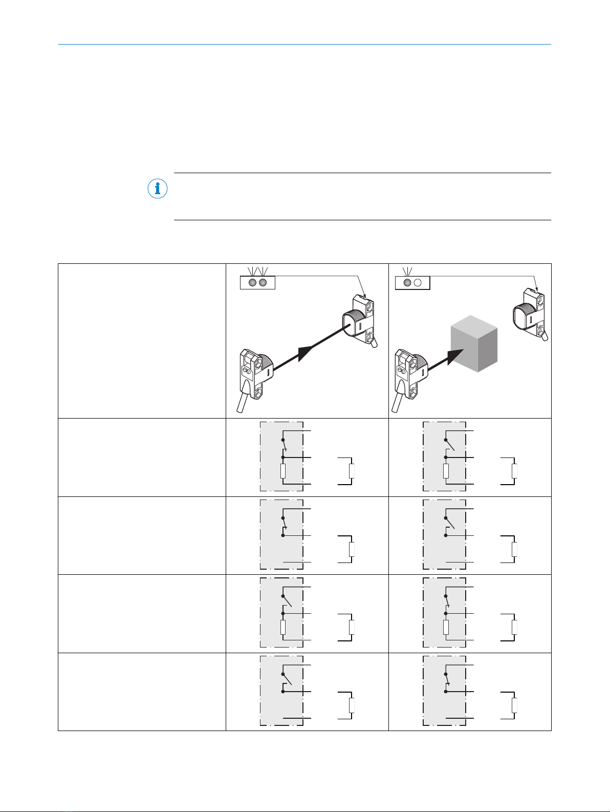
4 Operating and status indicators
Figure 1: Status indicators
1LED indicator (green): power
2LED indicator (orange): light received
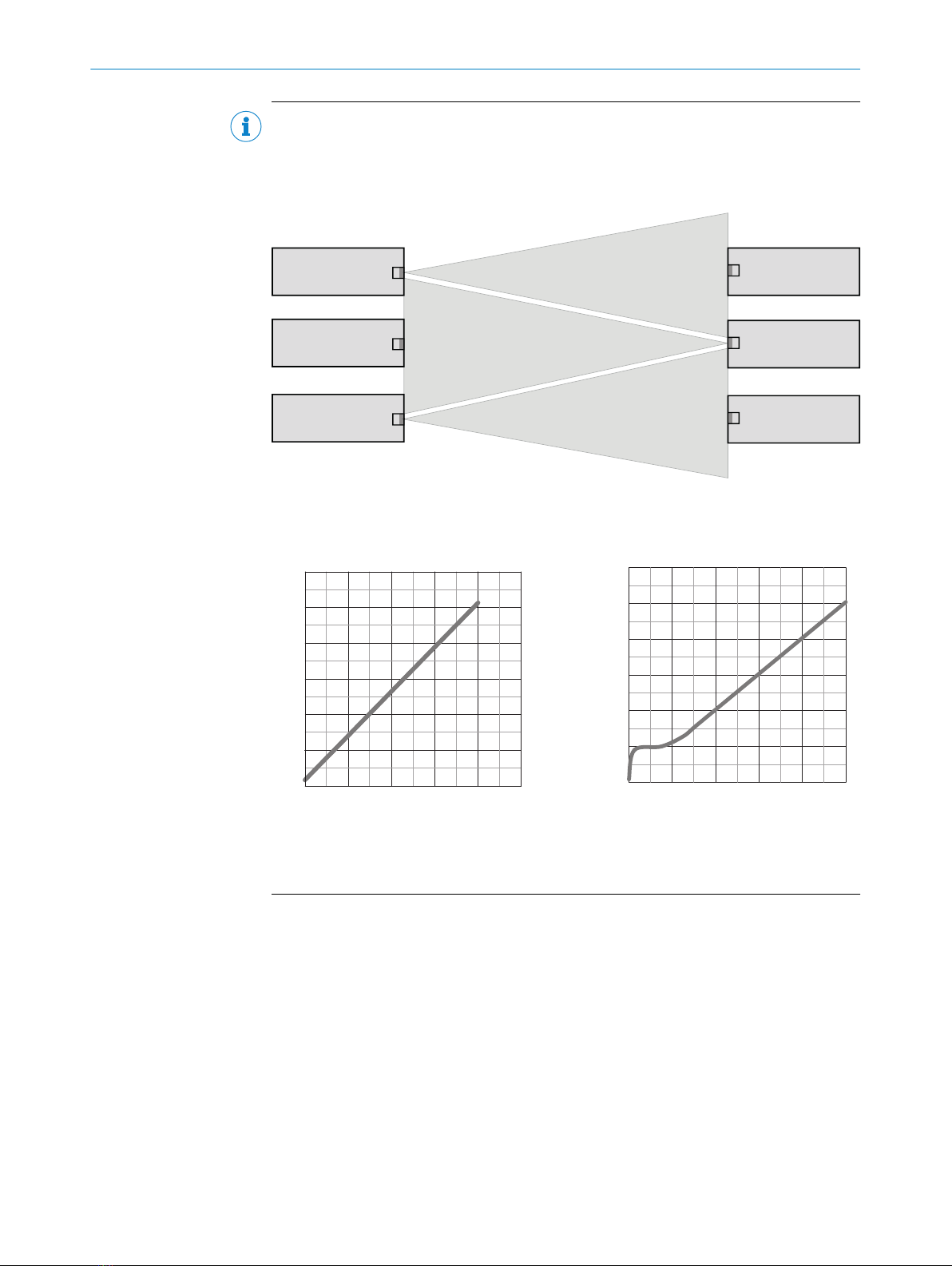
5 Mounting
Mount sensors (sender and receiver) using suitable mounting brackets (see the SICK
range of accessories). Align the sender and receiver with each other.
GENERAL SAFETY NOTES 1
8021945 | SICK
Subject to change without notice 5