SICK LD-LRS User manual

OPERATING INSTRUCTIONS
LD-LRS
2D LiDAR sensor

Described product
LD-LRS
•LD-LRS3600 (field application and CoLa A/B)
•LD-LRS3601 (raw data measurement sensor with USP and CoLa A/B)
•LD-LRS3611 (raw data measurement sensor with USP, CoLa A/B and extended
scanning range)
Manufacturer
SICK AG
Erwin-Sick-Str. 1
79183 Waldkirch
Germany
Legal information
This work is protected by copyright. Any rights derived from the copyright shall be
reserved for SICK AG. Reproduction of this document or parts of this document is
only permissible within the limits of the legal determination of Copyright Law. Any modi‐
fication, abridgment or translation of this document is prohibited without the express
written permission of SICK AG.
The trademarks stated in this document are the property of their respective owner.
© SICK AG. All rights reserved.
Original document
This document is an original document of SICK AG.
2O P E R A T I N G I N S T R U C T I O N S | LD-LRS 8016506/1G07/2020-11-08 | SICK
Subject to change without notice

Contents
1 About this document........................................................................ 5
1.1 Information on the operating instructions.............................................. 5
1.2 Explanation of symbols............................................................................ 5
1.3 Further information................................................................................... 6
2 Safety information............................................................................ 7
2.1 Intended use............................................................................................. 7
2.2 Improper use............................................................................................. 7
2.3 Cybersecurity............................................................................................ 7
2.4 Limitation of liability................................................................................. 8
2.5 Modifications and conversions................................................................ 8
2.6 Requirements for skilled persons and operating personnel.................. 8
2.7 Operational safety and specific hazards................................................. 9
3 Product description........................................................................... 10
3.1 Scope of delivery....................................................................................... 10
3.2 Status indicators....................................................................................... 10
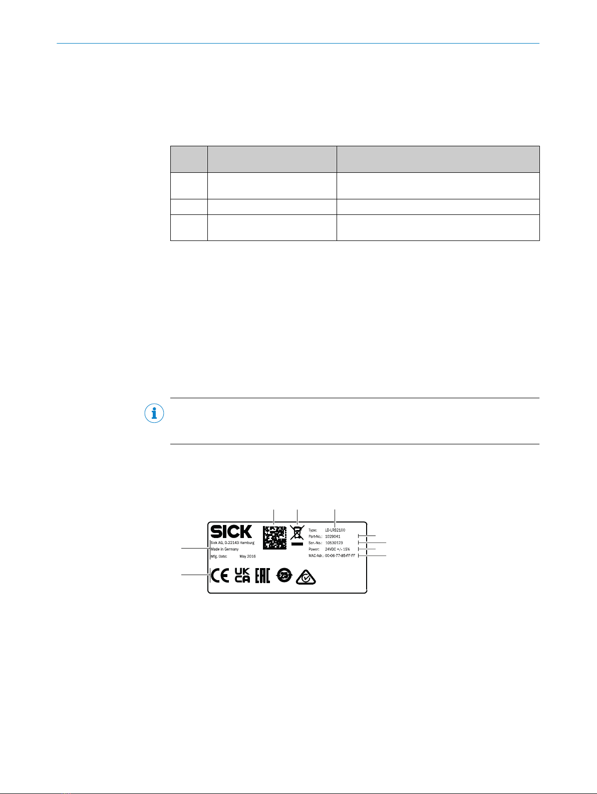
3.3 Type label.................................................................................................. 10
3.4 Principle of operation............................................................................... 11
3.4.1 Measurement principle........................................................... 11
3.4.2 Range finding........................................................................... 11
3.4.3 Direction measurement.......................................................... 11
3.4.4 Impact of object surfaces on the measurement................... 12
3.4.5 Beam diameter and measuring point distance..................... 14
3.4.6 Minimum object size................................................................ 16
3.4.7 Maximum and average pulse rate.......................................... 17
3.4.8 Output of measured values..................................................... 18
3.4.9 Multi-echo analysis.................................................................. 18
3.4.10 Field application (LD-LRS3600)............................................. 19
3.4.11 Integration into other controllers............................................ 20
4 Transport and storage....................................................................... 24
4.1 Transport................................................................................................... 24
4.2 Unpacking.................................................................................................. 24
4.3 Transport inspection................................................................................. 24
4.4 Storage...................................................................................................... 24
5 Mounting............................................................................................. 25
5.1 Mounting instructions............................................................................... 25
5.2 Mounting the device................................................................................. 25
5.3 Mounting multiple devices....................................................................... 25
6 Electrical installation........................................................................ 26
6.1 Wiring instructions.................................................................................... 26
6.2 Prerequisites for safe operation of the device........................................ 26
CONTENTS
8016506/1G07/2020-11-08 | SICK O P E R A T I N G I N S T R U C T I O N S | LD-LRS 3
Subject to change without notice

6.3 Overview of the installation steps............................................................ 29
6.4 Connection diagram................................................................................. 29
7 Commissioning.................................................................................. 31
7.1 Overview of the commissioning steps..................................................... 31
7.2 SOPAS ET configuration software............................................................ 31
7.3 Establishing communication with the device......................................... 32
7.4 Initial commissioning................................................................................ 33
7.5 Connecting and performing a test measurement.................................. 34
8 Maintenance...................................................................................... 36
8.1 Maintenance plan..................................................................................... 36
8.2 Cleaning..................................................................................................... 36
9 Troubleshooting................................................................................. 37
9.1 General faults, warnings, and errors....................................................... 37
9.2 Repairs...................................................................................................... 38
9.3 Returns...................................................................................................... 38
9.4 Disposal..................................................................................................... 38
10 Technical data.................................................................................... 39
10.1 Features.................................................................................................... 39
10.2 Mechanics/Electronics............................................................................. 40
10.3 Performance............................................................................................. 40
10.4 Interfaces.................................................................................................. 41
10.5 Dimensional drawing................................................................................ 42
10.6 Ambient data............................................................................................. 42
11 Accessories........................................................................................ 43
12 Annex.................................................................................................. 44
12.1 Declarations of conformity and certificates............................................ 44
12.2 Licenses.................................................................................................... 44
CONTENTS
4O P E R A T I N G I N S T R U C T I O N S | LD-LRS 8016506/1G07/2020-11-08 | SICK
Subject to change without notice

1 About this document
1.1 Information on the operating instructions
These operating instructions provide important information on how to use devices from
SICK AG.
Prerequisites for safe work are:
•Compliance with all safety notes and handling instructions supplied.
•Compliance with local work safety regulations and general safety regulations for
device applications
The operating instructions are intended to be used by qualified personnel and electrical
specialists.
NOTE
Read these operating instructions carefully to familiarize yourself with the device and its
functions before commencing any work.
The operating instructions are an integral part of the product. Store the instructions
in the immediate vicinity of the device so they remain accessible to staff at all times.
Should the device be passed on to a third party, these operating instructions should be
handed over with it.
These operating instructions do not provide information on the handling and safe
operation of the machine or system in which the device is integrated. Information on
this can be found in the operating instructions for the machine or system.
1.2 Explanation of symbols
Warnings and important information in this document are labeled with symbols. Sig‐
nal words introduce the instructions and indicate the extent of the hazard. To avoid
accidents, damage, and personal injury, always comply with the instructions and act
carefully.
DANGER
…indicates a situation of imminent danger, which will lead to a fatality or serious
injuries if not prevented.
WARNING
…indicates a potentially dangerous situation, which may lead to a fatality or serious
injuries if not prevented.
CAUTION
…indicates a potentially dangerous situation, which may lead to minor/slight injuries if
not prevented.
NOTICE
…indicates a potentially harmful situation, which may lead to material damage if not
prevented.
NOTE
…highlights useful tips and recommendations as well as information for efficient and
trouble-free operation.
ABOUT THIS DOCUMENT 1
8016506/1G07/2020-11-08 | SICK O P E R A T I N G I N S T R U C T I O N S | LD-LRS 5
Subject to change without notice

1.3 Further information
More information can be found on the product page.
The call is made via the SICK Product ID: pid.sick.com/{P/N}/{S/N}
{P/N} corresponds to the part number of the product, see type label.
{S/N} corresponds to the serial number of the product, see type label (if indicated).
The following information is available depending on the product:
•Data sheets
•This document in all available language versions
•CAD files and dimensional drawings
•Certificates (e.g., declaration of conformity)
•Other publications
•Software
•Accessories
1 ABOUT THIS DOCUMENT
6O P E R A T I N G I N S T R U C T I O N S | LD-LRS 8016506/1G07/2020-11-08 | SICK
Subject to change without notice

2 Safety information
2.1 Intended use
The LD-LRS 2D LiDAR sensor is intended exclusively for use in industrial environments.
Radio interference may result when used in residential areas.
The LD-LRS automates ship loading operations when using ship-to-shore cranes. The
laser optics system performs non-contact scanning of the container stack and precisely
detects all obstacles impeding the loading. The precise measurement data from the
LD-LRS is used to determine the profile data of the container stacks.
The profile measurement of the filling condition of bulk material stockpiles can be
converted into a 3D model to determine the exact surface structure of the stockpile to
control the loading system.
In conjunction with the field application, the LD-LRS can also be used for building safety
and security and for monitoring a variety of access zones outdoors.
Possible fields of application
•Container automation: position determination and detection
•Piece goods: measurement of the shape, position and volume of objects
•Crane control: profile measurement, collision protection, position detection and
guidance
•Surveying: floor plan surveying, longitudinal and transverse profiles in buildings
•Buildings: object protection, access monitoring, protection of facades and areas
(LD-LRS3600 only)
SICK AG assumes no liability for losses or damage arising from the use of the product,
either directly or indirectly. This applies in particular to use of the product that does not
conform to its intended purpose and is not described in this documentation.
2.2 Improper use
Any use outside of the stated areas, in particular use outside of the technical specifica‐
tions and the requirements for intended use, will be deemed to be incorrect use.
•The device does not constitute a safety component in accordance with the respec‐
tive applicable safety standards for machines.
•The device must not be used in explosion-hazardous areas, in corrosive environ‐
ments or under extreme environmental conditions.
•Any use of accessories not specifically approved by SICK AG is at your own risk.
WARNING
Danger due to improper use!
Any improper use can result in dangerous situations.
Therefore, observe the following information:
■Product should be used only in accordance with its intended use.
■All information in the documentation must be strictly observed.
■Shut down the product immediately in case of damage.
2.3 Cybersecurity
Overview
To protect against cybersecurity threats, it is necessary to continuously monitor and
maintain a comprehensive cybersecurity concept. A suitable concept consists of organi‐
zational, technical, procedural, electronic, and physical levels of defense and considers
SAFETY INFORMATION 2
8016506/1G07/2020-11-08 | SICK O P E R A T I N G I N S T R U C T I O N S | LD-LRS 7
Subject to change without notice

suitable measures for different types of risks. The measures implemented in this
product can only support protection against cybersecurity threats if the product is used
as part of such a concept.
You will find further information at www.sick.com/psirt, e.g.:
•General information on cybersecurity
•Contact option for reporting vulnerabilities
•Information on known vulnerabilities (security advisories)
2.4 Limitation of liability
Relevant standards and regulations, the latest technological developments, and our
many years of knowledge and experience have all been taken into account when
compiling the data and information contained in these operating instructions. The
manufacturer accepts no liability for damage caused by:
■Non-adherence to the product documentation (e.g., operating instructions)
■Incorrect use
■Use of untrained staff
■Unauthorized conversions or repair
■Technical modifications
■Use of unauthorized spare parts, consumables, and accessories
2.5 Modifications and conversions
NOTICE
Modifications and conversions to the device may result in unforeseeable dangers.
Interrupting or modifying the device or SICK software will invalidate any warranty claims
against SICK AG. This applies in particular to opening the housing, even as part of
mounting and electrical installation.
2.6 Requirements for skilled persons and operating personnel
WARNING
Risk of injury due to insufficient training.
Improper handling of the device may result in considerable personal injury and material
damage.
■All work must only ever be carried out by the stipulated persons.
The following qualifications are required for various activities:
Table 1: Activities and technical requirements
Activities Qualification
Mounting, maintenance ■Basic practical technical training
■Knowledge of the current safety regulations in the workplace
Electrical installation,
device replacement
■Practical electrical training
■Knowledge of current electrical safety regulations
■Knowledge of the operation and control of the devices in their
particular application
Commissioning, configura‐
tion
■Basic knowledge of the computer operating system used
■Basic knowledge of the design and setup of the described
connections and interfaces
■Basic knowledge of data transmission
2 SAFETY INFORMATION
8O P E R A T I N G I N S T R U C T I O N S | LD-LRS 8016506/1G07/2020-11-08 | SICK
Subject to change without notice

Activities Qualification
Operation of the device for
the particular application
■Knowledge of the operation and control of the devices in their
particular application
■Knowledge of the software and hardware environment for the
particular application
2.7 Operational safety and specific hazards
Please observe the safety notes and the warnings listed here and in other sections
of this product documentation to reduce the possibility of risks to health and avoid
dangerous situations.
CAUTION
Optical radiation: Class 1 Laser Product
The accessible radiation does not pose a danger when viewed directly for up to 100
seconds. It may pose a danger to the eyes and skin in the event of incorrect use.
■Do not open the housing. Opening the housing may increase the level of risk.
■Current national regulations regarding laser protection must be observed.
Caution – Use of controls or adjustments or performance of procedures other than
those specified herein may result in hazardous radiation exposure.
It is not possible to entirely rule out temporary disorienting optical effects, particularly
in conditions of dim lighting. Disorienting optical effects may come in the form of
dazzle, flash blindness, afterimages, photosensitive epilepsy, or impairment of color
vision, for example.
WARNING
Electrical voltage!
Electrical voltage can cause severe injury or death.
■Work on electrical systems must only be performed by qualified electricians.
■The power supply must be disconnected when attaching and detaching electrical
connections.
■The product must only be connected to a voltage supply as set out in the require‐
ments in the operating instructions.
■National and regional regulations must be complied with.
■Safety requirements relating to work on electrical systems must be complied with.
WARNING
Risk of injury and damage caused by potential equalization currents!
Improper grounding can lead to dangerous equipotential bonding currents, which may
in turn lead to dangerous voltages on metallic surfaces, such as the housing. Electrical
voltage can cause severe injury or death.
■Work on electrical systems must only be performed by qualified electricians.
■Follow the notes in the operating instructions.
■Install the grounding for the product and the system in accordance with national
and regional regulations.
SAFETY INFORMATION 2
8016506/1G07/2020-11-08 | SICK O P E R A T I N G I N S T R U C T I O N S | LD-LRS 9
Subject to change without notice

3 Product description
3.1 Scope of delivery
The delivery of the device includes the following components:
Table 2: Scope of delivery
No. of
units
Component Note
1 Device in the version ordered Depending on version
Without connecting cables and brackets
1 Lens cloth For cleaning the optics cover
1 Printed safety notes, multilin‐
gual
Brief information and general safety notes
3.2 Status indicators
Operator interface
The device works fully automatically in normal operation and requires no operator
intervention.
The SOPASET configuration software allows interactive configuration. For this, the
software runs on a computer which is connected to the device with one of the data
interfaces.
The graphical scan display in SOPASET is used to verify the generated measured
values and the measuring range online.
NOTE
Scans in SOPAS ET are not displayed in real time, but at a limited speed. Not all
measured values are displayed for this reason.
3.3 Type label
The type label gives information for identification of the device.
2
6
9
3
8
7
1
45
Figure 1: LD-LRS type label (example)
1Type code
2Part number
3Serial number
4Voltage supply
5MAC address
6Conformity mark/certification mark
7Manufacturer, place of production, production date
8Data Matrix code with product data and link to product page
9WEEE marking
3 PRODUCT DESCRIPTION
10 O P E R A T I N G I N S T R U C T I O N S | LD-LRS 8016506/1G07/2020-11-08 | SICK
Subject to change without notice

3.4 Principle of operation
3.4.1 Measurement principle
The device is an optoelectronic LiDAR sensor that contactlessly scans the outline of its
surroundings with the help of laser beams. The device measures its surroundings in
two-dimensional polar coordinates, relative to its measurement origin. This is marked
by a circular indentation in the center of the optics cover. If a laser beam strikes an
object, the position of that object is determined in terms of distance and angle.
Figure 2: LiDAR sensor with one scan plane
3.4.2 Range finding
The device emits beams pulsed by a laser diode. If the laser beam is reflected by an
object, the reflected beam is received by the sensor.
The distance to the object is calculated on the basis of the time that the pulsed light
beam requires to be reflected and received by the sensor.
t
1 2
1Emitted pulse
2Receive pulse
3.4.3 Direction measurement
The scanner head rotates at a selectable frequency of 5 to 15Hz. A laser pulse and
thus a distance measurement is triggered continuously after each angle increment.
In interlaced mode, individual scans are taken offset at an angle one to the other with
the maximum resolution that is technically possible. Combining the scans externally
enables a higher overall resolution to be achieved.
PRODUCT DESCRIPTION 3
8016506/1G07/2020-11-08 | SICK O P E R A T I N G I N S T R U C T I O N S | LD-LRS 11
Subject to change without notice

3.4.4 Impact of object surfaces on the measurement
Remission value
Remission is the ability of a material to reflect light. The remission correlates with the
amount of laser light emitted by the LiDAR sensor which is reflected by an object (see
Lambert’s law).
Glossy surfaces have different remissions at the same distance with different angles of
impact. In the case of shiny surfaces, maximum remission is achieved when the beam
makes vertical impact.
Matt and dull surfaces have diffuse remission. They therefore exhibit similar relative
remissions with the same angle of impact regardless of the distance from the zero
point.
Table 3: Typical remissions of frequently used materials
Material Typ. relative remission
Rubber tires (vulcanized, black) 2%
Foam rubber (black) 2.4%
Photographic board (black, matte) 10%
Cardboard (gray) 20%
Wood (untreated fir, soiled) 40%
PVC (gray) 50%
Paper (white, matte) 80%
Plaster (white) 100%
Aluminum (black anodized) 110 … 150%
Steel (stainless, shiny) 120 … 150%
Steel (high gloss) 140 … 200%
Reflection
Most surfaces produce a diffuse reflection of the laser beam in all directions. The
structure (smooth or rough), shape (flat or curved), and color (light or dark) of the
surface determine how well the laser beam is reflected.
On very rough surfaces, a large proportion of the energy is lost due to absorption.
Curved surfaces produce a higher diffusion. Dark surfaces reflect the laser beam worse
than light ones (brilliant white plaster reflects approx. 100% of the light, while black
foam rubber reflects approx. 2.4%). The aforementioned surface characteristics can
reduce the scanning range of the device, in particular for surfaces with low remission
values.
Figure 3: Reflection of light on the surface of the object
3 PRODUCT DESCRIPTION
12 O P E R A T I N G I N S T R U C T I O N S | LD-LRS 8016506/1G07/2020-11-08 | SICK
Subject to change without notice

Angle of reflection
The angle of reflection corresponds to the angle of incidence. If the laser beam hits
a surface at right angles, the energy is optimally reflected. If the laser beam hits a
surface at an oblique angle, energy and range are lost accordingly.
Figure 4: Angle of reflection
Retroreflection
If the reflective energy is greater than 100%, the beam is not reflected diffusely in all
directions; instead it is reflected in a targeted way (retroreflection). Thus a large part of
the emitted energy can be received by the laser distance measurer. Plastic reflectors
(cat’s eyes), reflective tape, and triple prisms have these properties.
Figure 5: Retroreflection
Reflective surfaces
The laser beam is almost completely deflected on reflective surfaces. This means that
an object hit by the deflected beam may be detected instead of the reflective surface.
Figure 6: Specular surfaces
Small objects
Objects that are smaller than the diameter of the laser beam cannot reflect the laser
light’s full energy. The portion of the light beam that does not reach the object is lost. If
all of the light reflected to the sensor is insufficient, the object may not be detected.
PRODUCT DESCRIPTION 3
8016506/1G07/2020-11-08 | SICK O P E R A T I N G I N S T R U C T I O N S | LD-LRS 13
Subject to change without notice

The portion of the light that does not reach the front object can be reflected by a larger
object in the background. If all of the light reflected to the sensor is sufficient, this
object is detected. This can lead to a corruption of the measured value.
Figure 7: Object smaller than the laser beam diameter
3.4.5 Beam diameter and measuring point distance
As the distance from the device increases, the laser beam expands. As a result, the
diameter of the measuring point increases on the surface of the object.
The range-dependent diameter of the measuring point corresponds to the distance
(mm) x 0.0028rad + 40mm.
Similarly, as the distance from the device increases, the individual measuring points
also grow further apart from one another. The distance between the measuring points
also depends on the selected angular resolution. The distance is larger with a coarser
angular resolution, and smaller with a finer angular resolution.
1
3
4
2
Figure 8: Schematic representation of the measuring point distance at different angular resolu‐
tions
1Scan at 0.375°
2Measuring point
3Scan at 0.25°
4Scan at 0.125°
The graph in figure 9shows the beam diameter and the measuring point distance
depending on the distance to the device.
3 PRODUCT DESCRIPTION
14 O P E R A T I N G I N S T R U C T I O N S | LD-LRS 8016506/1G07/2020-11-08 | SICK
Subject to change without notice

1400
Size [mm]
Distance [m]
Beam diameter
80
Beam diameter
Measuring point distance
0
010 20 30 40 50 60 70
1000
100
500
1,0°
0,5°
0,25°
0,125°
2
4
1
2
3
Figure 9: Beam diameter and measuring point distance at 0 to 80m
1Size [mm]
2Beam diameter
3Distance [m]
4Measuring point distance
Reading example for an angular resolution of 0.125° in figure 9
•60m distance
•A distance intersection point of 60m results in a measuring point distance of
approx. 130mm
•For a distance intersection point at 60m and based on the characteristic curve for
beam diameter, the beam expansion is approx. 200mm
•Result: No gaps in the scan
PRODUCT DESCRIPTION 3
8016506/1G07/2020-11-08 | SICK O P E R A T I N G I N S T R U C T I O N S | LD-LRS 15
Subject to change without notice

4500
Size [mm]
Distance [m]
Beam diameter
Beam diameter
Measuring point distance
0
050 100 150 200 250
4000
500
1,0°
0,5°
0,25°
0,125°
3000
2000
1000
1
2
3
4
2
Figure 10: Beam diameter and measuring point distance at 0 to 250m
1Size [mm]
2Beam diameter
3Distance [m]
4Measuring point distance
Reading example for an angular resolution of 0.50° in figure 10
•150m distance
•For a distance intersection point at 150m, the measuring point distance is
approx. 1,100mm
•For a distance intersection point at 150m and based on the characteristic curve
for beam diameter, the beam expansion is approx. 450mm
•Result: Gaps of approx. 650mm during scanning, minimum object size >650mm
3.4.6 Minimum object size
For an object to be detected reliably, it must be hit completely by a laser beam once. If
the beam only partially hits, less energy may be reflected from the object see "Principle
of operation", page 11.
An object is then reliably hit completely at any time if it is at least as large as the
measuring point distance plus the beam diameter.
3 PRODUCT DESCRIPTION
16 O P E R A T I N G I N S T R U C T I O N S | LD-LRS 8016506/1G07/2020-11-08 | SICK
Subject to change without notice

Scan 1
Scan 2
Scan 3
1
2
Figure 11: Minimum object size for detection
1Beam diameter
2Measuring point distance
In the example in figure 11, the object is fully hit at least once during each scan. It is
therefore reliably detected if it has the necessary remission.
How to calculate the minimum object size:
Beam diameter + measuring point distance = minimum object size
•Beam diameter and measuring point distance as a function of the distance to the
device can be seen in the diagram in see figure 9, page 15.
NOTE
For reliable measurement, in particular when using the device to output measured
values, the laser needs to hit the object several times. Therefore, the object either
needs to be larger than the minimum object size, or both the device and the object
must not be moving.
When using the field application, an object usually has to be hit several times in a row
to be recognized as interrupting the field.
3.4.7 Maximum and average pulse rate
The scanner head of the device rotates at a selectable frequency of 5 to 12Hz. A
laser pulse and thus a distance measurement is triggered continuously after an angle
increment of for example 0.25° (configurable). The faster the scanner head rotates,
the faster the output of measured values, and the finer the angular resolution is
configured, the more accurate the contour determination.
NOTE
In this case the selected interface of the device and the downstream host must be able
to transmit or process that amount of data.
PRODUCT DESCRIPTION 3
8016506/1G07/2020-11-08 | SICK O P E R A T I N G I N S T R U C T I O N S | LD-LRS 17
Subject to change without notice

NOTE
The laser diode heats up with each laser pulse. Like all semiconductors, a laser diode is
destroyed by excessive temperatures. The pulse rate is therefore limited.
The maximum pulse rate of the laser diode must never exceed 14.4kHz. The maximum
pulse rate is determined by the number of revolutions per second of the head and the
angular resolution.
The average pulse rate must not exceed 10.8kHz. The average pulse rate is deter‐
mined by the maximum pulse rate and the size of the scan range.
•For a scan range of 360°, the average pulse rate is equal to the maximum pulse
rate.
•For a scan range <360°, the average pulse rate is lower than the maximum pulse
rate.
Table 4: Examples for the maximum and average pulse rate
Scan
range
Revolu‐
tions of
the head
Angular
resolution
Maximum
pulse rate
Average
pulse rate
LD-
LRS3601/
3611
LD-
LRS36
00
Example 1 360° 15Hz 1/2°=0.5
°
10.8kHz 10.8kHz x x1)
Example 2 300° 10Hz 1/4°=0.2
5°
12kHz 10kHz x x
Example 3 300° 5Hz 1/8°=0.1
25°
12kHz 10kHz x x
1) Available for raw data measurement only (field application)
3.4.8 Output of measured values
The device outputs the following measured values at its data interfaces:
•Profile of the field of view in two-dimensional polar coordinates
•Content of one revolution (360°): Number of the profile emitted, profile counter,
sector numbers, step width, number of points per sector, time stamp for start/end
of each sector, direction at the start/end of each sector, value and direction of the
distances measured, status
NOTE
It is only possible to output all measured values of a 360° scan in real time using the
Ethernet interface.
3.4.9 Multi-echo analysis
The distance between the device and an object is calculated via the time-of-flight of the
emitted pulse. The device can evaluate up to three echo signals for each measuring
beam to deliver reliable measurement results, even under adverse ambient conditions.
3 PRODUCT DESCRIPTION
18 O P E R A T I N G I N S T R U C T I O N S | LD-LRS 8016506/1G07/2020-11-08 | SICK
Subject to change without notice

1Fog
2Rain
3Measuring object
3.4.10 Field application (LD-LRS3600)
The device uses the integrated field application to analyze up to six detection fields
within its scan range. You can use the field application to, for example, implement
systems for collision protection, object protection, or access monitoring.
1
2
3
10
1
2
3
6
&,≥1...
OUT1 OUT2 OUT3
Operator for the outputs
Evaluation cases
- Evaluation field
- Evaluation strategy
- Output
Evaluation fields
&,≥1... &,≥1...
6
1
2
3
4
5
7 8 9OUT4
&,≥1...
ß
Figure 12: Principle of field application
1Detection fields
2Evaluation cases
PRODUCT DESCRIPTION 3
8016506/1G07/2020-11-08 | SICK O P E R A T I N G I N S T R U C T I O N S | LD-LRS 19
Subject to change without notice

3Detection field
4Analysis strategy
5Output
6Linking of outputs
7OUT1
8OUT2
9OUT3
ßOUT4
The device is adapted to the evaluation scenario with the help of up to ten evaluation
cases.
In the evaluation case, one of six configurable detection fields, an evaluation strategy,
and an output that activates the evaluation case is selected. For each output, a link
is chosen which determines the result of the output if more than one evaluation case
affects the output.
In the example in see figure 12, detection field1 is used in evaluation case1, and
detection field2 is used in evaluation case2. Both evaluation cases act on output
OUT1. If the results of the evaluation cases are AND-linked, the output only switches
when both evaluation cases report an event.
The field application is active when the device is delivered.
NOTE
If you activate or deactivate the field application, the parameter display in SOPAS is
adjusted accordingly.
To deactivate the field application of the LD-LRS3600:
•In the Project tree, open LD-LRS36xx, Parameters, Default. You can activate or deacti‐
vate the field application by selecting Raw data scan in the Application selection area.
3.4.11 Integration into other controllers
NOTE
Integrating a device into other controllers requires in-depth programming knowledge of
controllers. You also need knowledge on exchanging data between a 2D LiDAR sensor
and an external computer, for example an industrial PC.
3.4.11.1 Data interfaces
The device has a serial host interface and an Ethernet interface. The device is config‐
ured via these interfaces using SOPASET. The device also communicates with the
external computer via its interfaces.
The default setting for the Ethernet interface
•IP address: 192.168.1.10
•Subnet mask: 255.255.255.0
•TCP/ IP port for SOPAS ET: 2112
•Selectable between CoLa A (ASCII) and CoLa B (binary)
3.4.11.2 Communicating data via telegrams
The device sends telegrams over the interfaces described above to communicate with a
connected host. The following functions can be run using telegrams:
3 PRODUCT DESCRIPTION
20 O P E R A T I N G I N S T R U C T I O N S | LD-LRS 8016506/1G07/2020-11-08 | SICK
Subject to change without notice
Table of contents
Other SICK Accessories manuals

SICK
SICK MLS Series User manual

SICK
SICK DL100 Pro User manual

SICK
SICK DL100 Pro User manual

SICK
SICK CSM User manual

SICK
SICK GRTE18S V Series User manual

SICK
SICK WTB4FT DoubleLine User manual

SICK
SICK DS500 User manual

SICK
SICK TriSpectorP1000 User manual

SICK
SICK MLS User manual

SICK
SICK GTE6L Series User manual

SICK
SICK MAX48 User manual

SICK
SICK RFU61 Series User manual

SICK
SICK MultiPulse WTB4-3P2100S14 User manual

SICK
SICK WL18-3 Series User manual

SICK
SICK SureSense HTB18L Series User manual

SICK
SICK SFU Series User manual

SICK
SICK HTE18 Series User manual

SICK
SICK MIS User manual

SICK
SICK ZSE18 Series User manual

SICK
SICK PowerProx WTT190L-K Series User manual