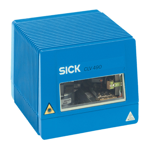
SICK CLV 45 Series User manual

CLV 45x
Bar Code Scanner
Advanced line
O
PERATING
I
NSTRUCTIONS

Operating Instructions
CLV 45x Bar Code Scanner
E-2 © SICK AG · Division Auto Ident · German · All rights reserved 8 009 139/K949/06-06-2002
Software versions
Described software versions
Windows 95TM/98TM, Windows NTTM, Windows XPTM and Internet-ExplorerTM are registered
trademarks or trademarks of the Microsoft Corporation in the USA and other countries.
Netscape NavigatorTM is a registered trademark of the Netscape Communications
Cooperation, USA.
I-View-ProTM is a registered trademark of EnReach Technolog , Inc., USA.
Software/Tool Function Version
CLV 45x Firmware V 3.03 K949
CLV-Setup User interface (Windows-based) V 3.2 L547
CLV-Setup Help Online help (HTML) From V 1.1
I-ViewProTM HTML browser (offline) From V 2.38

Operating Instructions
CLV 45x Bar Code Scanner
Quick Finder
8 009 139/K949/06-06-2002 © SICK AG · Division Auto Ident · German · All rights reserved E-3
CLV 5x bar code scanner
Quick Finder
•What is delivered with the device
–Chapter 3.1.1 Scope of delivery, Page 3-1
•Caution!
–Chapter 2 Safety information, Page 2-1
•Mounting the device at the reading station
–Chapter 4 Installation, Page 4-1
•Connecting the device
–Chapter 5 lectrical installation, Page 5-1
•Overview of the device and its functions
–Chapter 3 Product description, Page 3-1
–Chapter 6.2 Default setting, Page 6-1
–Chapter 6.5 Operating modes and output of the read result, Page 6-18
–Chapter 9 Technical data, Page 9-1
•Starting the device with the default settings
–Chapter 6.3 Quick-Start, Page 6-3
•Installing the “CLV-Setup“ user software on the PC
–Chapter 10.4 Installing and operating the "CLV-Setup" PC software, Page 10-20
•Adapting the device to the reading application
–Chapter 6.4 Configuration (parameterizing), Page 6-4
•Help in cases of problems
–Chapter 8 Troubleshooting, Page 8-1
•Finding information
–Table of contents, Page -5
–Chapter 10.16 Index, Page 10-66

Operating Instructions
CLV 45x Bar Code Scanner
E- © SICK AG · Division Auto Ident · German · All rights reserved 8 009 139/K949/06-06-2002
Quick Finder
Installation steps (overview)
Reading trigger via “Sensor 1“ switching input (default setting)
1. Check whether the deliver is complete.
2. Install the CLV in the reading station and align to the object with bar code.
3. Install the AMV/S 40 connection module and cover the terminal designations in the
connection area.
4. Connect the CLV to the AMV/S 40 connection module.
5. Install the reading-pulse sensor.
6. Connect the reading-pulse sensor to the "Sensor 1" switching input in the AMV/S 40.
7. Install the sensor for the distance detection.
8. Connect the distance sensor to the "Sensor 2" switching input in the AMV/S 40.
9. Connect the host to the "Host interface" in the AMV/S 40.
Adapt the AMV/S 40 to the host interface t pe of the CLV.
10. Switch on the suppl voltage of the AMV/S 40.
After the CLV has been started the "Device Read " LED lights up. The beeper signals
that Reading mode has been started b means of two consecutive sounds.
Line scanner with oscillating mirror:
In reading mode the CLV deflects the scan line in the default setting with a frequenc of
1 Hz around the position CW = 50 at a maximum angle of ±20°.
11. Switch on the PC and start WindowsTM (minimum requirement Windows 95TM).
12. Install the supplied "CLV-Setup" user software, "CLV-Setup Help" online help and, if re-
quired, "I-ViewProTM" HTML browser from the CD-ROM on the PC.
13. Connect the PC to the terminal interface of the CLV.
To this purpose connect the PC via the RS-232 data connection cable to the "Service"
plug in the AMV/S 40.
14. Start the "CLV-Setup" software.
CLV-Setup starts the communication with the CLV and copies the parameter record of
the CLV b means of an upload. The parameter record is displa ed in the tab cards.
15. Carr out a test read run with a test bar code specimen (pulse the CLV correspondingl ).
Displa the read result in the terminal emulator of CLV-Setup.
16. Configure the CLV for the application b means of the setting options on the tab cards
in CLV-Setup.
Cop the modified parameter record temporaril to the CLV per download.
Do not switch off the suppl voltage of the AMV/S 40 (of the CLV).
17. Test the application under real conditions.
18. Check the correct data transfer of the CLV to the host.
19. If necessar , correct and optimize the set parameter values.
Cop the parameter record permanently to the CLV per download.
20. Save the parameter record as a configuration file "*.scl" in CLV-Setup!
The CLV is read to operate with the application-specific setting.

Operating Instructions
CLV 45x Bar Code Scanner
Contents
8 009 139/K949/06-06-2002 © SICK AG · Division Auto Ident · German · All rights reserved E-5
Table of contents
1 Notes on this document .............................................................................................. 1-1
1.1 Function.......................................................................................................................................... 1-1
1.2 Target audience .......................................................................................................................... 1-1
1.2.1 Installation, electrical installation, maintenance, device replacement............ 1-1
1.2.2 Startup, operation and configuration .......................................................................... 1-1
1.3 Information content ................................................................................................................... 1-1
1.4 S mbols used .............................................................................................................................. 1-2
2 Safety information ......................................................................................................... 2-1
2.1 Authorized users ......................................................................................................................... 2-1
2.1.1 Installation and maintenance......................................................................................... 2-1
2.1.2 Electrical installation and replacing devices............................................................. 2-1
2.1.3 Startup, operation and configuration .......................................................................... 2-1
2.2 Intended use ................................................................................................................................ 2-1
2.3 General safet instructions and protective measures ................................................. 2-1
2.4 Quick Stop and Quick Restart................................................................................................ 2-3
2.4.1 Switching off the CLV ........................................................................................................ 2-3
2.4.2 Switching on the CLV again ............................................................................................ 2-3
2.5 Environmental information ...................................................................................................... 2-4
2.5.1 Power requirement ............................................................................................................ 2-4
2.5.2 Disposal after final removal from service.................................................................. 2-4
3 Product description....................................................................................................... 3-1
3.1 Design............................................................................................................................................. 3-1
3.1.1 Scope of deliver ................................................................................................................ 3-1
3.1.2 Device variants.................................................................................................................... 3-1
3.1.3 S stem requirements ....................................................................................................... 3-1
3.1.4 Design line scanner ........................................................................................................... 3-3
3.1.5 Design line scanner with oscillating mirror................................................................ 3-4
3.2 Working method of the device .............................................................................................. 3-5
3.2.1 Changeable focal position............................................................................................... 3-6
3.2.2 Variants of the scanning process................................................................................. 3-6
3.3 Displa and operating elements........................................................................................... 3-7
3.3.1 Operating elements ........................................................................................................... 3-7
3.3.2 Function of the LEDs......................................................................................................... 3-7
3.3.3 Function of the beeper (buzzer) ................................................................................... 3-9
Installation ....................................................................................................................... -1
4.1 Overview of the installation steps ........................................................................................ 4-1
4.2 Preparations for installation.................................................................................................... 4-1
4.2.1 La ing out the components to be installed read ................................................. 4-1
4.2.2 La ing out the accessories read ................................................................................ 4-1
4.2.3 La ing out the required tools read ............................................................................. 4-1
4.2.4 Replacing the laser warning label................................................................................. 4-2
4.2.5 Selecting the installation site ......................................................................................... 4-2
4.2.6 Mounting accessories.......................................................................................................4-3
4.2.7 Distance between the CLV and the bar code ......................................................... 4-4
4.2.8 Counting direction of the code position CP and of the code angle CW ........ 4-6
4.3 Installation and adjustment of the device......................................................................... 4-8
4.3.1 Installing the CLV ................................................................................................................ 4-8
4.3.2 Adjusting the CLV................................................................................................................ 4-8
4.3.3 Auxiliar functions for adjusting...................................................................................4-10
4.4 Installing the external components....................................................................................4-11
4.4.1 Installing the AMV/S 40 connection module .........................................................4-11
4.4.2 Installing an external reading-pulse sensor............................................................4-12
4.4.3 Mounting the sensor for detecting the object distance ....................................4-13
4.5 Disassembling the device .....................................................................................................4-14
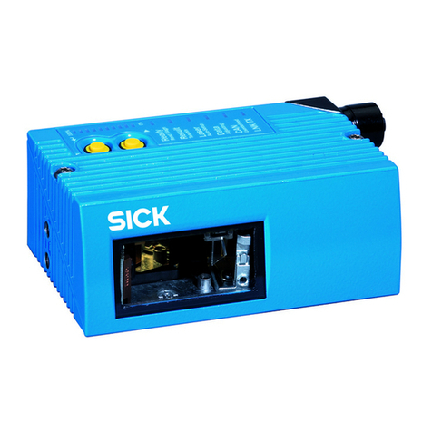
Operating Instructions
CLV 45x Bar Code Scanner
E-6 © SICK AG · Division Auto Ident · German · All rights reserved 8 009 139/K949/06-06-2002
Contents
5 Electrical installation.................................................................................................... 5-1
5.1 Overview of the installation step ...........................................................................................5-1
5.2 Electrical connections and cables ........................................................................................5-1
5.2.1 Connections/Cables when the AMV/S 40 connection module is used ........5-1
5.3 Pin assignment of the connecting plug...............................................................................5-2
5.4 Preparation of the electrical installation .............................................................................5-2
5.4.1 Requirements for the host interface ...........................................................................5-2
5.4.2 Suppl voltage......................................................................................................................5-3
5.4.3 Non-SICK suppl s stem device/wiring without SICK connection module...5-3
5.5 Carr ing out the electrical installation..................................................................................5-4
5.5.1 Overview of the connection steps................................................................................5-4
5.5.2 Aids...........................................................................................................................................5-4
5.5.3 Connecting the suppl voltage.......................................................................................5-4
5.5.4 Wiring the host interface ..................................................................................................5-5
5.5.5 Connecting the CAN interface........................................................................................5-6
5.5.6 Connecting the PC..............................................................................................................5-6
5.5.7 Wiring the "Sensor 1" switching input .......................................................................5-7
5.5.8 Wiring the "Sensor 2" switching input.........................................................................5-8
5.5.9 Wiring the "Result 1" and "Result 2" switching outputs ......................................5-9
6 Operation.......................................................................................................................... 6-1
6.1 Overview of the startup steps................................................................................................6-1
6.2 Default setting ..............................................................................................................................6-1
6.2.1 Default setting of line scanner.......................................................................................6-2
6.2.2 Default setting of line scanner with oscillating mirror............................................6-2
6.3 Quick-Start .....................................................................................................................................6-3
6.3.1 Starting up the line scanner/line scanner with oscillating mirror
with the factor default setting ......................................................................................6-3
6.4 Configuration (parameterizing)...............................................................................................6-4
6.4.1 Configuring the CLV b means of the CLV-Setup user interface......................6-4
6.4.2 Function of the tab cards in CLV-Setup (overview) ...............................................6-6
6.4.3 Guide to parameterization...............................................................................................6-8
6.4.4 Configuring the CLV with Auto Setup........................................................................6-14
6.5 Operating modes and output of the read result .......................................................... 6-18
6.5.1 Reading mode (Standard mode)............................................................................... 6-18
6.5.2 Percentage evaluation ...................................................................................................6-21
6.5.3 Adjusting mode.................................................................................................................6-23
6.5.4 Show CP limits................................................................................................................... 6-23
6.5.5 Displa ing and editing operating data......................................................................6-25
6.5.6 Reading diagnosis............................................................................................................6-25
6.5.7 Host interface monitoring .............................................................................................6-26
6.5.8 Auxiliar input..................................................................................................................... 6-28
6.5.9 Self-test................................................................................................................................6-28
6.5.10 Carr ing out device functions of the CLV in the dialog box .............................6-29
6.6 Messages of the CLV ............................................................................................................. 6-30
6.6.1 Displa ing messages......................................................................................................6-30
6.6.2 S stem messages........................................................................................................... 6-30
6.6.3 Warnings.............................................................................................................................. 6-30
6.6.4 Error messages ................................................................................................................ 6-30
6.7 Switching off the CLV.............................................................................................................. 6-31
7 Maintenance ................................................................................................................... 7-1
7.1 Maintenance during operation...............................................................................................7-1
7.2 Maintenance .................................................................................................................................7-2
7.3 Disposal ..........................................................................................................................................7-2
8 Troubleshooting ............................................................................................................. 8-1
8.1 Overview of the possible errors and malfunctions.........................................................8-1

Operating Instructions
CLV 45x Bar Code Scanner
Contents
8 009 139/K949/06-06-2002 © SICK AG · Division Auto Ident · German · All rights reserved E-7
8.1.1 Mounting errors................................................................................................................... 8-1
8.1.2 Faults during the electrical installation ....................................................................... 8-1
8.1.3 Parameterization errors ................................................................................................... 8-1
8.1.4 Faults during operation ....................................................................................................8-1
8.2 Monitoring error and fault signs............................................................................................ 8-1
8.3 Error messages........................................................................................................................... 8-2
8.4 ST error status in the read result of a bar code............................................................. 8-5
8.5 Troubleshooting........................................................................................................................... 8-6
8.5.1 General malfunctions: CLV not read ......................................................................... 8-6
8.5.2 Malfunction in Reading mode: Reading pulsing errors ........................................ 8-7
8.5.3 Malfunctions in Reading mode: Result output errors ........................................... 8-9
8.5.4 Malfunctions in Reading mode: Errors in the result status output ................8-12
8.5.5 Malfunctions in Reading mode: Oscillating mirror operation errors..............8-13
8.5.6 Malfunctions: Configuration errors (parameterization) ......................................8-14
8.6 SICK Support..............................................................................................................................8-14
9 Technical data ................................................................................................................ 9-1
9.1 Data sheet CLV 45x line scanner ....................................................................................... 9-1
9.2 Data sheet CLV 45x line scanner with oscillating mirror............................................. 9-2
9.3 Dimensional drawings CLV...................................................................................................... 9-3
9.3.1 Line scanner......................................................................................................................... 9-3
9.3.2 Line scanner with oscillating mirror ............................................................................. 9-4
10 Appendix........................................................................................................................ 10-1
10.1 Appendix overview ...................................................................................................................10-1
10.2 Specification diagrams ...........................................................................................................10-2
10.2.1 Reading conditions for all diagrams ..........................................................................10-2
10.2.2 Overview of diagrams .....................................................................................................10-2
10.2.3 Reading ranges of CLV 450 line scanner/line scanner with
oscillating mirror................................................................................................................10-3
10.2.4 Depths of field for CLV 450 line scanner (front-end reading window) ........10-5
10.2.5 Depths of field for CLV 450 line scanner with oscillating mirror
(side-end reading window)............................................................................................10-9
10.2.6 Depths of field for CLV 451 line scanner (front-end reading window) .....10-13
10.2.7 Depths of field for CLV 451 line scanner with oscillating mirror
(side-end reading window).........................................................................................10-15
10.2.8 Characteristics field scanning frequenc (maximum values) .......................10-17
10.2.9 Deflection range of CLV 450 line scanner with oscillating mirror...............10-18
10.2.10 Deflection range of CLV 451 line scanner with oscillating mirror...............10-18
10.3 S stem messages.................................................................................................................10-19
10.4 Installing and operating the "CLV-Setup" PC software............................................10-20
10.4.1 Preparing the installation ............................................................................................10-20
10.4.2 Carr ing out the installation .......................................................................................10-20
10.4.3 Starting "CLV-Setup"....................................................................................................10-22
10.4.4 CLV-Setup user interface ...........................................................................................10-24
10.4.5 Functions ..........................................................................................................................10-25
10.4.6 "CLV-Setup Help" online help...................................................................................10-25
10.4.7 Transferring a parameter record between CLV-Setup and the CLV..........10-26
10.4.8 Handling unknown parameters ................................................................................10-26
10.4.9 Recording the log file in the terminal emulator ..................................................10-27
10.4.10 Starting CLV-Setup with an INI file as an argument .........................................10-27
10.4.11 CLV Assistant ..................................................................................................................10-27
10.5 Configuring the CLV b means of Profile bar codes.................................................10-28
10.5.1 Activate Auto Setup with Profile bar code............................................................10-28
10.5.2 Profile progamming.......................................................................................................10-30
10.6 Configuring the CLV with command strings.................................................................10-33
10.7 Calculating parameter values for setting the CLV.....................................................10-35
10.7.1 Calculating the number of scans (for standard decoders) ...........................10-35
10.7.2 Calculating the start position and mirror speed for the forward

Operating Instructions
CLV 45x Bar Code Scanner
E-8 © SICK AG · Division Auto Ident · German · All rights reserved 8 009 139/K949/06-06-2002
Contents
and return phase of the One-Shot function........................................................ 10-37
10.7.3 Calculating the necessar distance if several bar codes are
read on each object..................................................................................................... 10-38
10.8 Auxiliar tables........................................................................................................................ 10-39
10.8.1 Calculating the code length of a bar code .......................................................... 10-39
10.9 Special applications and procedures ............................................................................ 10-40
10.9.1 Triggering the Teach-in match code 1 via the "Sensor 2"
switching input................................................................................................................ 10-40
10.9.2 Auxiliar input via terminal interface....................................................................... 10-45
10.9.3 "Building a Dais -chain configuration"
(data forwarding or master/slave arrangement) .............................................. 10-48
10.9.4 SICK network (RS 485).............................................................................................. 10-48
10.9.5 Connection to the Profibus DP................................................................................. 10-48
10.9.6 Connection to the DeviceNet................................................................................... 10-48
10.9.7 Connection to the Interbus-S ................................................................................... 10-48
10.9.8 Connection to Ethernet............................................................................................... 10-49
10.9.9 Building a CAN Scanner Network............................................................................ 10-49
10.10 Replacing a CLV (cop ing the parameter record) .................................................... 10-49
10.10.1 Transferring the parameter set using Profile bar codes................................ 10-49
10.10.2 Transferring the parameter record b means of a download...................... 10-50
10.11 Available accessories.......................................................................................................... 10-51
10.11.1 Mounting accessories................................................................................................. 10-51
10.11.2 Connection modules.................................................................................................... 10-51
10.11.3 Bus connection modules ........................................................................................... 10-52
10.11.4 Cables and connectors............................................................................................... 10-52
10.11.5 Reading pulse generation.......................................................................................... 10-53
10.11.6 Network controller ........................................................................................................10-53
10.12 Dimensioned drawings of the accessories................................................................. 10-54
10.12.1 Mounting bracket No. 2 020 410 (for one CLV)........................................... 10-54
10.12.2 Mounting bracket No. 2 022 564.......................................................................... 10-54
10.12.3 Rod clamp No. 2 023 691 ....................................................................................... 10-55
10.12.4 Mounting bracket with vibration damper No. 2 031 342............................. 10-55
10.13 Supplementar documentation ....................................................................................... 10-56
10.14 Glossar .................................................................................................................................... 10-57
10.15 Cop of the EC Declaration of Conformit ................................................................... 10-64
10.17 Bar code sample................................................................................................................... 10-69

Operating Instructions
CLV 45x Bar Code Scanner
Figures and tables
8 009 139/K949/06-06-2002 © SICK AG · Division Auto Ident · German · All rights reserved E-9
Abbreviations used
DC Distance Configuration
AMV/S Connection module with distributor (signal)/with additional power suppl
BMV/S Bus connection module with distributor (signal)/with additional power suppl
CAN Controller Area Network (standard field bus s stem with message-orientated data ex-
change protocol)
CLV Code reader V principle. The bar code scanner CLV 45x is designated for all the t pes
simpl as a "CLV", except at text positions where a differentiation is required.
DOF Depth Of Field
EEPROM Electricall Erasable Programmable Read Onl Memor
HTML H per Text Markup Language (page description language in Internet)
LED Light Emitting Diode
RAM Random Access Memor
ROM Read Onl Memor
RTF Rich Text Format (standardized document format with format descriptions)
PLC Programmable Logic Controller
SMART SICK Modular Advanced Recognition Technolog
Tables
Table 3-1: Variants of the CLV 45x ..................................................................................................3-1
Table 3-2: Meaning of the LEDs........................................................................................................3-8
Table 3-3: Function of the beeper....................................................................................................3-9
Table 4-1: Permitted reading angle between the scan line and the bar code................4-5
Table 5-1: Pin assignment of the 15-pin D-Sub HD cable plug ............................................5-2
Table 5-2: Maximum cables lengths between the CLV and the host.................................5-2
Table 5-3: Power consumption of the CLV....................................................................................5-3
Table 5-4: Power-up dela as a function of the device number GN ...................................5-3
Table 5-5: Wire color assignment of cable No. 6 010 137 (open end).........................5-4
Table 5-6: Communication parameters of the host interface (default setting)...............5-5
Table 5-7: Characteristic data of the "Sensor 1" switching input ........................................5-7
Table 5-8: Focal position changeover: Assignment table switching input –
distance configuration......................................................................................................5-9
Table 5-9: Characteristic data of the switching outputs "Result 1" and "Result 2" ...5-10
Table 6-1: Extract: Default setting of the line scanner parameter values.........................6-2
Table 6-2: Extract: Default setting of additional parameter values of the
line scanner with oscillating mirror..............................................................................6-2
Table 6-3: Reading distances of CLV 450 and CLV 451 (default) for quick start .........6-4
Table 6-4: Guide: Parameterizing the changeover of the distance configuration/
focal position .......................................................................................................................6-8
Table 6-5: Guide: Parameterizing the oscillating reading mirror functions........................6-9
Table 6-6: Guide: Parameterizing the reading pulse source ...............................................6-12
Table 6-7: Guide: Parameterizing the laser timeout ...............................................................6-12
Table 6-8: Guide: Settings to be carried out for evaluating identical bar codes .........6-13
Table 6-9: "Host interface monitoring" function.......................................................................6-26
Table 6-10: Warning...............................................................................................................................6-30
Table 8-1: Error messages output via the terminal interface ................................................8-2
Table 8-2: Meaning of the ST error status in the read result.................................................8-5
Table 8-3: Troubleshooting: Restoring operation (Reading mode)......................................8-6
Table 8-4: Troubleshooting: Reading pulsing errors in Reading mode...............................8-7
Table 8-5: Troubleshooting: Result output errors in Reading mode....................................8-9
Table 8-6: Troubleshooting: Errors in the result status output in Reading mode........8-12

Operating Instructions
CLV 45x Bar Code Scanner
E-10 © SICK AG · Division Auto Ident · German · All rights reserved 8 009 139/K949/06-06-2002
Figures and tables
Table 8-7: Troubleshooting: Oscillating mirror errors in Reading mode...........................8-13
Table 8-8: Troubleshooting: Configuration errors (parameterization) ..............................8-14
Table 9-1: Technical specifications line scanner ........................................................................ 9-1
Table 9-2: Technical specifications line scanner with oscillating mirror............................. 9-2
Table 10-1: Reading conditions for specification diagrams ....................................................10-2
Table 10-2: Overview CLV 45x specification diagrams ............................................................10-2
Table 10-3: CLV 450: Optimum of scanning frequencies ....................................................10-17
Table 10-4: CLV s stem messages ..............................................................................................10-19
Table 10-5: Default settings of CLV-Setup (extract)...............................................................10-22
Table 10-6: Function of the preprinted Profile bar codes on card No. 8 008 085....10-33
Table 10-7: Auxiliar table for calculating the code length of a bar code.......................10-39
Table 10-8: Communication parameters to be set on the terminal/PC for the
auxiliar input .................................................................................................................10-47
Table 10-9: Communication parameter to be set for the ST 1100 decoder...............10-48
Table 10-10: Available accessories: Mounting accessories ..................................................10-51
Table 10-11: Available accessories: Connection modules.....................................................10-51
Table 10-12: Accessories: Bus Connection modules...............................................................10-52
Table 10-13: Available accessories: Cables and connectors................................................10-52
Table 10-14: Available accessories: Network controller..........................................................10-53
Table 10-15: Supplementar documentation in English ..........................................................10-56
Figures
Fig. 2-1: Laser warning label attached to the CLV (valid for Europe)................................. 2-2
Fig. 3-1: Design of the line scanner CLV 45x.............................................................................. 3-3
Fig. 3-2: Design of the line scanner with oscillating mirror CLV 45x .................................. 3-4
Fig. 3-3: Block diagram: Functions of the CLV............................................................................ 3-5
Fig. 3-4: Focal position changeover: Division of the overall reading range into
distance configurations ...................................................................................................... 3-6
Fig. 3-5: Oscillating mirror: Example of the focal position changeover in the
search run ............................................................................................................................... 3-7
Fig. 3-6: LEDs .......................................................................................................................................... 3-8
Fig. 4-1: Example of line scanner: Exchanging the laser warning label............................. 4-2
Fig. 4-2: Example of line scanner: Position of the fastening thread at the CLV............. 4-3
Fig. 4-3: Line scanner: Example of the mounting possibilities of the CLV with the
mounting bracket No. 2 020 410 ................................................................................. 4-3
Fig. 4-4: Line scanner: Example of the mounting possibilities of the CLV with the
mounting bracket No. 2 022 564 ................................................................................. 4-4
Fig. 4-5: Positioning of the scanning process to the bar code and to the conve or
direction ................................................................................................................................... 4-4
Fig. 4-6: Definition of the reading distance a and of the aperture angle a...................... 4-5
Fig. 4-7: Line scanner: Reading angle occurring between the scan line and
the bar code........................................................................................................................... 4-5
Fig. 4-8: Avoiding surface reflections: Angle between the emitted light and
the bar code (tilted awa from the perpendicular).................................................. 4-6
Fig. 4-9: Counting direction of the code position CP within the scan line and
of the code angle CW at an oscillating mirror............................................................ 4-7
Fig. 4-10: Line scanner: Appearance of the scan line in the "Adjusting mode"
operating mode...................................................................................................................4-10
Fig. 4-11: Correction of the printed terminal assignment in the connection area
of the AMV/S 40.................................................................................................................4-11
Fig. 4-12: Line scanner: Installation example for positioning the external
reading-pulse sensor ........................................................................................................4-12
Fig. 4-13: CLV 44x: Installation example for positioning the object distance
detection................................................................................................................................4-13
Fig. 5-1: Block diagram: Connection of the CLV to the AMV/S 40 connection
module...................................................................................................................................... 5-1

Operating Instructions
CLV 45x Bar Code Scanner
Figures and tables
8 009 139/K949/06-06-2002 © SICK AG · Division Auto Ident · German · All rights reserved E-11
Fig. 5-2: Wiring the host interface ....................................................................................................5-5
Fig. 5-3: Wiring the terminal interface.............................................................................................5-6
Fig. 5-4: Wiring of the "Sensor 1" switching input......................................................................5-7
Fig. 5-5: Wiring of the "Sensor 2" switching input......................................................................5-8
Fig. 5-6: Wiring of the "Result 1" switching output ....................................................................5-9
Fig. 6-1: Bar code patter for CLV 450 (Code 39; module width 0.35 mm;
Print ratio 2:1) ........................................................................................................................6-3
Fig. 6-2: Bar code patter for CLV 451 (Code 39; module width 0.5 mm;
Print ratio 2:1) ........................................................................................................................6-4
Fig. 6-3: "Oscillating with fixed amplitude" operating mode................................................6-10
Fig. 6-4: "Oscillating with variable amplitude" operating mode .........................................6-10
Fig. 6-5: One-Shot: Object tracking (bar code read from front).........................................6-11
Fig. 6-6: CLV-Setup: Displa ing the course of the Auto Setup in the
terminal emulator...............................................................................................................6-16
Fig. 6-7: CLV-Setup: Displa ing the read result of the terminal interface in the
terminal emulator...............................................................................................................6-19
Fig. 6-8: Read result of the terminal interface: Structure for “Good Read“ .................. 6-20
Fig. 6-9: Read result of the terminal interface: Structure for “No Read“........................6-20
Fig. 6-10: CLV-Setup: Displa ing the percentage evaluation in the
terminal emulator...............................................................................................................6-22
Fig. 6-11: Appearance of scan line in the "Show CP-limits" mode .....................................6-24
Fig. 6-12: CLV-Setup: "Operating Data" dialog box...................................................................6-25
Fig. 6-13: CLV-Setup: Output of the read result of the host interface in the terminal
emulator at the beginning (in this case: O = Output)...........................................6-27
Fig. 6-14: CLV-Setup: Outputting the self-test result in the terminal emulator...............6-28
Fig. 6-15: CLV-Setup: Dialog box for executing the Auto Setup...........................................6-29
Fig. 7-1: Cleaning the reading window............................................................................................7-1
Fig. 7-2: Cleaning the external optical sensors (reading clock generator,
object height detection)......................................................................................................7-2
Fig. 9-1: Dimensions of the line scanner.......................................................................................9-3
Fig. 9-2: Dimensions of the line scanner with oscillating mirror ...........................................9-4
Fig. 10-1: CLV 450-0010: Reading ranges about all focal positions for line scanner 10-3
Fig. 10-2: CLV 450-6010: Reading ranges about all focal positions for line
scanner with oscillating mirror.......................................................................................10-4
Fig. 10-3: CLV 450-0010: Min. and max. reading distance for the line scanner as a
function of the focal position at a resolution of 0.25 mm..................................10-5
Fig. 10-4: CLV 450-0010: Min. and max. reading distance for the line scanner as a
function of the focal position at a resolution of 0.35 mm..................................10-6
Fig. 10-5: CLV 450-0010: Min. and max. reading distance for the line scanner as a
function of the focal position at a resolution of 0.50 mm..................................10-7
Fig. 10-6: CLV 450-0010: Min. and max. reading distance for the line scanner as a
function of the focal position at a resolution of 1.00 mm..................................10-8
Fig. 10-7: CLV 450-6010: Min. and max. reading distance for the line scanner with
oscillating mirror as a function of the focal position at a resolution
of 0.25 mm ..........................................................................................................................10-9
Fig. 10-8: CLV 450-6010: Min. and max. reading distance for the line scanner with
oscillating mirror as a function of the focal position at a resolution
of 0.35 mm .......................................................................................................................10-10
Fig. 10-9: CLV 450-6010: Min. and max. reading distance for the line scanner with
oscillating mirror as a function of the focal position at a resolution
of 0.50 mm .......................................................................................................................10-11
Fig. 10-10: CLV 450-6010: Min. and max. reading distance for the line scanner with
oscillating mirror as a function of the focal position at a resolution
of 1.00 mm .......................................................................................................................10-12
Fig. 10-11: CLV 451-0010: Min. and max. reading distance for the line scanner
as a function of the focal position and the tilt at a resolution of 0.5 mm
and an aperture angle of 25• ................................................................................... 10-13
Fig. 10-12: CLV 451-0010: Min. and max. reading distance for the line scanner

Operating Instructions
CLV 45x Bar Code Scanner
E-12 © SICK AG · Division Auto Ident · German · All rights reserved 8 009 139/K949/06-06-2002
Figures and tables
as a function of the focal position and the tilt at a resolution of 0.5 mm
and an aperture angle of 55• ....................................................................................10-14
Fig. 10-13: CLV 451-6010: Min. and max. reading distance for the line scanner
with oscillating mirror as a function of the focal position and the tilt at a
resolution of 0.5 mm and an aperture angle of 25• ........................................10-15
Fig. 10-14: CLV 451-6010: Min. and max. reading distance for the line scanner
with oscillating mirror as a function of the focal position and the tilt at a
resolution of 0.5 mm and an aperture angle of 55• ........................................10-16
Fig. 10-15: CLV 450: Characteristics field scanning frequenc as a function of
the reading distance and resolution ........................................................................10-17
Fig. 10-16: CLV 450-6010: Deflection range as a function of the reading distance,
the angle of deflection and the resolution.............................................................10-18
Fig. 10-17: CLV 451-6010: Deflection range as a function of the reading distance
and the angle of deflection at a resolution of 0.5 mm .....................................10-18
Fig. 10-18: CLV-Setup: Result displa of the AutoBaud-Detect ...........................................10-23
Fig. 10-19: User interface of the "CLV-Setup" software .........................................................10-24
Fig. 10-20: CLV-Setup: Entering commands in the terminal emulator ..............................10-34
Fig. 10-21: Line scanner: Calculating the number of scans for ladder-t pe bar code
positioning ..........................................................................................................................10-35
Fig. 10-22: Line scanner: Calculating the number of scans for fence-t pe bar code
positioning ..........................................................................................................................10-35
Fig. 10-23: Line scanner with oscillating mirror: Calculating the number of scans for
fence-t pe bar code positioning ................................................................................10-36
Fig. 10-24: One-Shot: Line scanner with oscillating mirror: Calculating the number
of scans for fence-t pe bar code positioning.......................................................10-37
Fig. 10-25: Required distance between the bar codes on an object.................................10-38
Fig. 10-26: Wiring of the "Sensor 2" switching input for triggering the teach-in
match code 1....................................................................................................................10-40
Fig. 10-27: Auxiliar input via the terminal interface of the CLV ...........................................10-46
Fig. 10-28: CLV-Setup: Auxiliar input on the terminal emulator..........................................10-47
Fig. 10-29: Dimensions of the mounting bracket No. 2 020 410 ......................................10-54
Fig. 10-30: Dimensions of the mounting bracket No. 2 022 564 ......................................10-54
Fig. 10-31: Dimensions of the rod clamp No. 2 023 691 .....................................................10-55
Fig. 10-32: Dimensions of the mounting bracket with vibration damper
No. 2 031 342.................................................................................................................10-55
Fig. 10-33: Reproduction of the declaration of conformit (Page 1, reduced in size).10-64
Fig. 10-34: Reproduction of the declaration of conformit (Page 2, reduced in size).10-65
Fig. 10-35: Scannable bar codes of various module widths (printing ratio 2:1)............10-69

Operating Instructions Chapter 1
CLV 45x Bar Code Scanner
Notes on this document
8 009 139/K949/06-06-2002 © SICK AG · Division Auto Ident · German · All rights reserved 1-1
1Notes on this document
1.1 Function
This document instructs ou on using the bar code scanner
•CLV 450 with d namic focal position adjustment
•CLV 451 with d namic focal position adjustment, optimized on 0.5 mm module width
in the variants
•Line scanner
•Line scanner with oscillating mirror
The document contains information on
•Device installation and electrical installation
•Startup
•Operation and configuration (parameterization)
•Maintenance
•Device replacement with importing of the parameter record
•Special applications and processes
The bar code scanners will all simpl be called "CLV" below, except in such text passages
where a differentiation is required.
1.2 Target audience
Target audience for this document are persons with the following activities:
1.2.1 Installation, electrical installation, maintenance, device replacement
Electricians and service technicians
1.2.2 Startup, operation and configuration
Technicians and engineers
1.3 Information content
This document contains all the information required for the installation, electrical installation
and startup of the CLV with the default setting in our works.
All actions are described step-b -step.
The configuration of the CLV for the application-specific read situation is carried out with
the Windows-oriented "CLV-Setup" PC software and the "CLV Assistant". The "CLV-Setup
Help" online help s stem is available as an additional help. Installation of the software and
use of the user interface are described in the appendix.
Further information on the construction of the bar code scanner as well as the bar code
technolog can be obtained from SICK AG, Auto Ident Division.

Chapter 1 Operating Instructions
CLV 45x Bar Code Scanner
1-2 © SICK AG · Division Auto Ident · German · All rights reserved 8 009 139/K949/06-06-2002
Notes on this document
1. Symbols used
Some information in this documentation is emphasized in order to facilitate rapid access to
this information:
Warning!
A "Warning" protects persons against injuries or the bar code scanner against serious da-
mage.
¾
Alwa s read warnings carefull and observe them exactl .
Note A "Note" informs on exceptional features.
Explanation An explanation provides background information on technical correlations.
Recommendation A "Recommendation" provides information on how to carr out an action optimall .
Hint A hint explains the setting possibilities in the user interface of the CLV-Setup.
Default setting Marks a section in which the values of the default setting of our works are listed.
SCANNING FREQUENCY This font characterizes a term used in the user interface of the CLV-Setup.
A s mbol refers to a command button in the user interface of the CLV-Setup.
"Host receive fault" This font characterizes messages which the CLV outputs via the terminal interface.
This s mbol characterizes a section in which the steps for using the user interface of the
CLV-Setup are described.
This s mbol characterizes a section in which the steps for using the profile programming are
described.
This s mbol refers to supplementar technical documentation.
¾
Here ou have to do something. This s mbol characterizes single-step operating instruc-
tions. Multiple-step operating instructions are characterized b sequential numbers.
Ö
Here ou select a function in the user interface of CLV-Setup.

Operating Instructions Chapter 2
CLV 45x Bar Code Scanner
Safety information
8 009 139/K949/06-06-2002 © SICK AG · Division Auto Ident · German · All rights reserved 2-1
2Safety information
2.1 Authorized users
The CLV must be installed and operated b qualified personnel in order to ensure that it
functions correctl and safel .
The following qualifications are required for the various activities:
2.1.1 Installation and maintenance
•Basic practical technical training
•Knowledge of the common safet instructions at the workplace
2.1.2 Electrical installation and replacing devices
•Practical electrical training
•Knowledge of the common electrical safet instructions
•Knowledge of the operation and handling of the devices of the respective application
(e. g. transport unit)
2.1.3 Startup, operation and configuration
•Knowledge of the operation and handling of the devices of the respective application
(e. g. transport unit)
•Knowledge of the software and hardware environment of the respective application
(e. g. transport unit)
•A basic knowledge of Windows 95TM/98TM, Windows NTTM or Windows XPTM
•Basic knowledge of a HTML browser, for example, Netscape NavigatorTM
•Basic knowledge of data transmission
•Basic knowledge of bar code technolog
2.2 Intended use
The CLV detects and decodes bar codes automaticall . It is installed in a reading station and
reads, for example, bar codes on objects of a conve or belt.
The CLV transfers the data contents of the decoded bar code via the host interface to a host
for further processing.
The user forfeits an warrant claims against SICK AG in case of an other use as well as in
case of changes to the device, also during device installation and electrical installation.
2.3 General safety instructions and protective measures
¾
Read the general safet instructions thoroughl and observe them strictl at all activities
at the CLV. Also observe the warnings before operating instructions in the individual
chapters of this document.

Chapter 2 Operating Instructions
CLV 45x Bar Code Scanner
2-2 © SICK AG · Auto Ident · German · All rights reserved 8 009 139/K949/06-06-2002
Safety information
Danger of injury through electrical current!
The AMS40 connection module (accessor ) for the CLV is connected to 230 V 50 Hz or
115 V AC 50/60 Hz suppl voltage, depending on the t pe.
¾
Observe the common safet regulations when working on electrical installations.
Laser radiation may cause damage to your eyes!
The CLV operates with a Class 2 red-light laser. The retina can be damaged if you look
too long into the laser beam.
¾
Never look directl into the laser beam (comparable with sunlight).
¾
Do not point the laser beam at persons.
¾
When mounting and aligning the CLV take the reflection of the laser beam against re-
flecting surfaces into account.
¾
Do not open the housing.
(Opening does not interrupt activation of the laser diode b the reading pulsing.)
¾
Observe the laser protection specifications in accordance with DIN EN 60825-1 (latest
version).
Laser performance
The laser operates with a wavelength of λ= 650 nm (visible red light). The power output of
the laser beam amounts to a max. of 3.5 mW at the reading window.
The emitted radiation is not dangerous to the human skin.
Laser warning labels
The laser warning labels relevant for Europe (Fig. 2-1) are located at the following points at
the CLV:
•At the line scanner the British/US version of the laser warning s mbol and the laser
warning are located next to the front-end reading window on the side surface (refer to
Fig. 3-1, Page 3-3).
•At the line scanner with oscillating mirror the British/US version of the laser warning s m-
bol and the laser warning are located on the side surface opposite the reading window
(refer to Fig. 3-2, Page 3-4).
Note The scope of deliver includes a set of laser warnings in German/US English and French/US
English. These can be stuck over the British/US warning.
If the CLV is installed in a machine/casing in such a manner that the laser warning
labels of the device is concealed, further warning labels (not included in the scope of
delivery) must be attached on the machine next to the aperture of the laser beam!
Fig. 2-1: Laser warning label attached to the CLV (valid for Europe)

Operating Instructions Chapter 2
CLV 45x Bar Code Scanner
Safety information
8 009 139/K949/06-06-2002 © SICK AG · Division Auto Ident · German · All rights reserved 2-3
Internal protective circuits
The CLV has monitoring circuits which shut off the laser diode when irregularities occur in
the beam generation.
The switching on and off of the laser diode during the reading process is controlled b the
reading pulsing (pulse source).
In the pulsing t pes "Sensor input" and "Serial interface" a timer (laser timeout) switches off
the laser diode automaticall 10 min (default setting) after the beginning of a lasting reading
pulse during reading mode. However it does not terminate the reading pulse. CLV outputs
the following message via the terminal interface:
"Laser safety timeout"
The reading pulse has to be terminated b means of a corresponding pulse signal. The next
reading pulse re-activates the laser diode.
The laser timeout can be set in the range of 1 min ... 25 h or de-activated (refer to
Table 6-7, Page 6-12).
The laser diode is always active in reading mode in the operating modes "Percentage
evaluation", "Adjusting mode", "Show CP limits" and "Auto setup" as well as in the
"free-running" pulsing type.
2. Quick Stop and Quick Restart
2. .1 Switching off the CLV
¾
Switch off the suppl voltage or pull off the cable plug of the CLV from the connection
module.
At most the following ma be lost:
•The application-specific parameter record, if it was onl saved temporarily in the CLV
•The last reading result
•Da operating data
(operating hours counter, trigger count, number of good reads, maximum duration
trigger, minimum duration trigger, average identification qualit )
2. .2 Switching on the CLV again
¾
Switch on the suppl voltage or pin up again the cable plug of the CLV to the connection
module.
The CLV restarts operation with the parameter record last saved permanently and re-
sets the da operating data.

Chapter 2 Operating Instructions
CLV 45x Bar Code Scanner
2- © SICK AG · Auto Ident · German · All rights reserved 8 009 139/K949/06-06-2002
Safety information
2.5 Environmental information
The CLV is designed so that it harms the environment as little as possible. It does not have
an materials using silicone and is therefore not a source of faults for, for example, coating
wetting in paint shops.
2.5.1 Power requirement
The power requirement is low.
•The line scanner consumes a max. of 6 W
•The line scanner with oscillating mirror consumes a max. of 7.2 W
The values each correspond to operation with open-circuited switching outputs.
2.5.2 Disposal after final removal from service
Dispose of unusable or irreparable devices in accordance with the respective state regula-
tions on waste disposal in a manner compatible with the environment. The design of the CLV
allows it to be separated into rec clable secondar raw materials and hazardous waste
(electronic scrap). Refer to Chapter 7.3 Disposal, Page 7-2.
At present SICK AG does not take back devices which have become unusable or
irreparable.

Operating Instructions Chapter 3
CLV 45x Bar Code Scanner
Product description
8 009 139/K949/06-06-2002 © SICK AG · Division Auto Ident · German · All rights reserved 3-1
3Product description
3.1 Design
3.1.1 Scope of delivery
The packaging of the CLV contains the following:
•An information sheet (Notes on device) with electrical wiring diagram and Quick-Start
•An additional set of laser warning lables (self-adhesive) for Class 2 in German/US
English and French/US English
•A lable with terminal designations for sticking over the connection designations of the
mother board of the AMV/S 40 connection module
Depending on the number of ordered devices one or more technical documentation
sets, consisting of:
•These CLV 45x operating instructions in English and German
•A CD-ROM containing the "CLV-Setup" software for WindowsTM, the "CLV-Setup Help"
online help s stem and the "I-ViewProTM" HTML browser
•A foldable card with 12 printed Profile bar codes
Chapter 10.11 Available accessories, Page 10-51 provides an overview of the available
mounting accessories, connection modules, cables and plug-and-socket connections as
well as sensors for reading pulse generation and detection of the object distance.
3.1.2 Device variants
The CLV is available in the following variants:
3.1.3 System requirements
The following are required to start up and operate the CLV:
1. A SICK connection module for power suppl and interconnection of the data and
function interfaces.
Available t pes:
−AMV 40-011 (No. 1 017 132) for 24 V DC ±20 %, enclosure rating max. IP 54
−AMS 40-013 (No. 1 017 135) for 230 V AC 50 Hz/24 V DC, enclosure rating
max. IP 54
−AMS 40-012 (No. 1 017 136) for 115 V AC 50/60 Hz/24 V DC, enclosure rating
max. IP 54
−AMV 100-011 (No. 6 021 105) for 10 ... 30 V DC , enclosure rating max. IP 65
−AMV 200-011 (No. 6 021 106) for 10 ... 30 V DC, enclosure rating max. IP 65
Type
(red light)
Order No. Scanning process Reading
window
CLV 450-0010 1 018 556 Line scanner On front
CLV 450-6010 1 019 218 Line scanner with oscillating mirror Lateral
CLV 451-0010 1 019 522 Line scanner, optimized on 0.5 mm
module width
On front
CLV 451-6010 1 019 524 Line scanner with oscillating mirror,
optimized on 0.5 mm module width
Lateral
Table 3-1: Variants of the CLV 45x

Chapter 3 Operating Instructions
CLV 45x Bar Code Scanner
3-2 © SICK AG · Division Auto Ident · German · All rights reserved 8 009 139/K949/06-06-2002
Product description
– or –
Alternativel a non-SICK suppl s stem device with an output voltage of 10 ... 30 V DC
in accordance with IEC 742 (functional extra-low voltage) and at least 10 W power out-
put. The connection cable No. 6 010 137 with 15-pin D-Sub-HD socket and open cable
end to connect the CLV to the suppl s stem device.
2. Following operating voltages/power output
–AMV40-011: 24 V DC ±20 %, according to IEC 742, min. 10 W
–AMS40-013: 230 V AC ±10 % 50 Hz
–AMS40-012: 115 V AC ±10 % 50/60 Hz
–AMV100-011: 10 ... 30 V DC according to IEC 742
–AMV200-011: 10 ... 30 V DC according to IEC 742
3. In the case of external reading pulsing via the "Sensor 1" switching input: A suitable
reading pulse sensor for signaling an object with bar code, for example, a photoelectric
reflex switch.
4. In the case of detection of the object distance via the "Sensor 2" switching input:
A suitable sensor for 2-stage focal position changeover, for example a photoelectric re-
flex switch.
5. A higher-level computer (host) with a data interface of t pe RS 422/485 or RS 232.
6. An optional interface converter No. 2 020 825 for installation in the AMV/S 40
connection module in order to connect the CLV to a 20 mA data interface.
7. A PC (al least 80486, 66 MHz, 16 MB RAM, CD-ROM drive, serial interface, mouse
(recommended)) with Windows 95TM/98TM, Windows NTTM or Windows XPTM.
8. An RS-232 data connection cable with two 9-pin D-Sub sockets for connecting the PC
to the terminal interface of the CLV in the AMV/S 40 connection module,
e. g. No. 2 014 054. Pin 2 (RxD) and Pin 3 (TxD) are transposed.
9. An HTML browser for using the "CLV-Setup Help" online help s stem, e. g. Netscape
NavigatorTM or the enclosed browser I-ViewProTM (refer to Chapter 3.1.1 Scope of deli-
very, Page 3-1).
10. For connection of the CLV to the Interbus S, the Profibus DP, DeviceNet or the Ethernet:
the corresponding BMV/BMH 10 Bus Connection Module (on request).
11. For connection of the CLV to the CAN Scanner Network: the Operating Instructions
“Application of the CAN interface“ (no. 8 009 180, English edition)
This manual suits for next models
4
Table of contents
Other SICK Barcode Reader manuals

SICK
SICK Lector621 User manual

SICK
SICK ICR 84x User manual

SICK
SICK CLV62 Series Manual

SICK
SICK CLV 410 Operating instructions

SICK
SICK Lector620 User manual

SICK
SICK IDM series User manual

SICK
SICK CLV610-C0000 User manual

SICK
SICK IDM series User manual

SICK
SICK CLV62x Reference guide

SICK
SICK ICD8 Series User manual

SICK
SICK CLP 100 User manual

SICK
SICK ICR845-2 User manual

SICK
SICK ICR803 User manual

SICK
SICK ICR803 User manual

SICK
SICK Advanced Series User manual

SICK
SICK CLV61 DualPort Series User manual

SICK
SICK CLV640 User manual

SICK
SICK CLV 41 Series User manual

SICK
SICK CLV60 series User manual

SICK
SICK CLV620 User manual