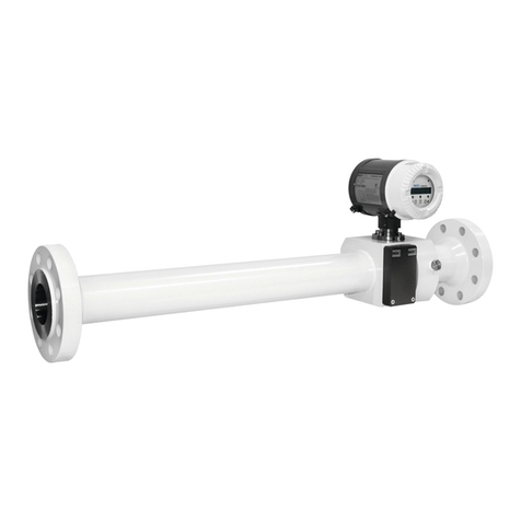
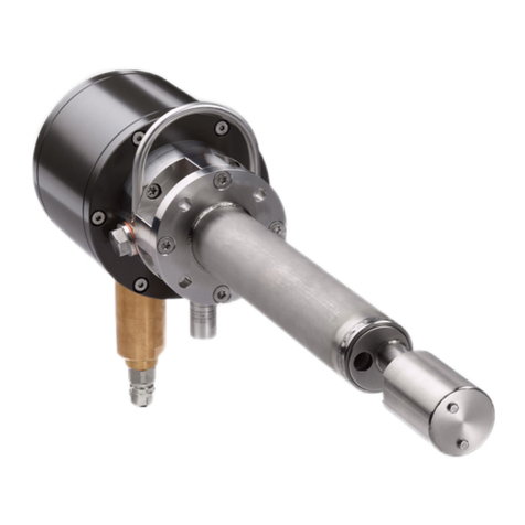
SICK FLOWSIC600-XT User manual

SERVICE MANUAL
Maintenance
Inspection
Repairs
Title Page
FLOWSIC600-XT
Ultrasonic Gas Meter

2 FLOWSIC600-XT · Service Manual · 8019179/V0-2/2016-03 · © SICK Engineering GmbH
Document Information
Described Product
Product name: FLOWSIC600-XT
Document ID
Title: Service Manual FLOWSIC600-XT
Part No.: 8019179
Document ID: 9238933
Version: 0-2
Release: 2016-03
Manufacturer
SICK Engineering GmbH
Bergener Ring 27 · D-01458 Ottendorf-Okrilla · Germany
Phone: +49 35 20552410
Fax: +49 35 20552450
E-Mail: info.pa@sick.de
Original document
The English version 8019179 of this document is an original docu-
ment from SICK Engineering GmbH.
SICK Engineering GmbH assumes no liability for the correctness of
an unauthorized translation.
Please contact SICK Engineering GmbH or your local representa-
tive in case of doubt.
Legal Information
Subject to change without notice.
© SICK Engineering GmbH. All rights reserved.
Glossary
ATEX ATEX: Atmosphères Explosifs: Abbreviation for Euro-
pean standards that govern safety in potentially
explosive atmospheres
CSA Canadian Standards Association (www.csa.ca)
DC Direct Current
HF High frequency, e.g. HF pulse
IEC International Electronical Commission
IECEx IEC system for certification in accordance with stan-
dards for devices for use in potentially explosive
atmospheres
IPxy Ingress Protection: Degree of protection of a device
in accordance with IEC/DIN EN 60529; xspecifies
the protection against contact and impurities, ypro-
tection against moisture.
MDR Manufacturer Data Record
NAMUR Abbreviation for "Normen-Arbeitsgemeinschaft für
Mess- und Regeltechnik in der chemischen Indu-
strie", now "Interessengemeinschaft Automatisie-
rungstechnik der Prozessindustrie" (www.namur.de)
SPU Signal Processing Unit

FLOWSIC600-XT · Service Manual · 8019179/V0-2/2016-03 · © SICK Engineering GmbH 3
Warning Symbols
Warning Levels / Signal Words
HAZARD
Risk or hazardous situation which will result in severe personal
injury or death.
WARNING
Risk or hazardous situation which could result in severe personal
injury or death.
CAUTION
Hazard or unsafe practice which could result in less severe or
minor injuries.
NOTICE
Hazard which could result in property damage.
Information Symbols
IMMEDIATE HAZARD
of severe injuries or death
Hazard (general)
Hazard by electrical voltage
Hazard in potentially explosive atmospheres
Hazard by explosive substances/mixtures
Hazard by unhealthy substances
Hazard by toxic substances
Information on product condition relating to protection
against explosions (general)
Information on product characteristics related to Euro-
pean Directive 94/9/EC (ATEX)
Information on product characteristics related to explo-
sion protection in accordance with the IECEx scheme.
Important technical information for this product
Important information on electric or electronic func-
tions
Nice to know
Supplementary information
Link referring to information at another place

Contents
4 FLOWSIC600-XT · Service Manual · 8019179/V0-2/2016-03 · © SICK Engineering GmbH
1 Important Information . . . . . . . . . . . . . . . . . . . . . . . . . . . . . . . . . . . . . . . . . . . . . . . 7
1.1 About this document . . . . . . . . . . . . . . . . . . . . . . . . . . . . . . . . . . . . . . . . . . . . . . . . . . . . . . . . . 8
1.2 For your safety . . . . . . . . . . . . . . . . . . . . . . . . . . . . . . . . . . . . . . . . . . . . . . . . . . . . . . . . . . . . . . 9
1.2.1 Intended use of the device . . . . . . . . . . . . . . . . . . . . . . . . . . . . . . . . . . . . . . . . . . . . . . . . . 9
1.2.2 Authorized personnel . . . . . . . . . . . . . . . . . . . . . . . . . . . . . . . . . . . . . . . . . . . . . . . . . . . . . . 9
1.2.3 General safety instructions and protective measures . . . . . . . . . . . . . . . . . . . . . . . . 10
1.2.4 Hazards by hot, corrosive and explosive gases, or high pressure . . . . . . . . . . . . . . 10
1.2.5 Hazard through heavy loads . . . . . . . . . . . . . . . . . . . . . . . . . . . . . . . . . . . . . . . . . . . . . . . 11
2 Components . . . . . . . . . . . . . . . . . . . . . . . . . . . . . . . . . . . . . . . . . . . . . . . . . . . . . . . . . . 13
2.1 Complete overview of the device family . . . . . . . . . . . . . . . . . . . . . . . . . . . . . . . . . . . . . . . 14
2.1.1 FLOWSIC600-XT . . . . . . . . . . . . . . . . . . . . . . . . . . . . . . . . . . . . . . . . . . . . . . . . . . . . . . . . . . 14
2.1.2 FLOWSIC600-XT Forte . . . . . . . . . . . . . . . . . . . . . . . . . . . . . . . . . . . . . . . . . . . . . . . . . . . . 15
2.1.3 FLOWSIC600-XT 2plex . . . . . . . . . . . . . . . . . . . . . . . . . . . . . . . . . . . . . . . . . . . . . . . . . . . . 16
2.1.4 FLOWSIC600-XT Quatro . . . . . . . . . . . . . . . . . . . . . . . . . . . . . . . . . . . . . . . . . . . . . . . . . . . 17
2.2 SPU (Signal Processing Unit) overview . . . . . . . . . . . . . . . . . . . . . . . . . . . . . . . . . . . . . . . . 18
2.2.1 Ex-d enclosure version . . . . . . . . . . . . . . . . . . . . . . . . . . . . . . . . . . . . . . . . . . . . . . . . . . . . 18
2.2.2 Ex-de enclosure version . . . . . . . . . . . . . . . . . . . . . . . . . . . . . . . . . . . . . . . . . . . . . . . . . . . 19
2.2.3 Ex-i enclosure version . . . . . . . . . . . . . . . . . . . . . . . . . . . . . . . . . . . . . . . . . . . . . . . . . . . . 20
3Repairs. . . . . . . . . . . . . . . . . . . . . . . . . . . . . . . . . . . . . . . . . . . . . . . . . . . . . . . . . . . . . . . . . 21
3.1 General information . . . . . . . . . . . . . . . . . . . . . . . . . . . . . . . . . . . . . . . . . . . . . . . . . . . . . . . . . 22
3.2 Prerequisites for repair work . . . . . . . . . . . . . . . . . . . . . . . . . . . . . . . . . . . . . . . . . . . . . . . . . 22
3.3 Tools required . . . . . . . . . . . . . . . . . . . . . . . . . . . . . . . . . . . . . . . . . . . . . . . . . . . . . . . . . . . . . . 23
3.4 Working on the meter body . . . . . . . . . . . . . . . . . . . . . . . . . . . . . . . . . . . . . . . . . . . . . . . . . . 24
3.4.1 Replacing the sensors . . . . . . . . . . . . . . . . . . . . . . . . . . . . . . . . . . . . . . . . . . . . . . . . . . . . 24
3.4.1.1 Remove the sensors . . . . . . . . . . . . . . . . . . . . . . . . . . . . . . . . . . . . . . . . . . . . . . . . . . . 24
3.4.1.2 Fit the new sensor . . . . . . . . . . . . . . . . . . . . . . . . . . . . . . . . . . . . . . . . . . . . . . . . . . . . . 26
3.4.2 Replacing the integrated p/T sensor . . . . . . . . . . . . . . . . . . . . . . . . . . . . . . . . . . . . . . . 28
3.4.2.1 Remove the p/T sensor . . . . . . . . . . . . . . . . . . . . . . . . . . . . . . . . . . . . . . . . . . . . . . . . 28
3.4.2.2 Fit the new p/T sensor . . . . . . . . . . . . . . . . . . . . . . . . . . . . . . . . . . . . . . . . . . . . . . . . . 29
Contents

Contents
FLOWSIC600-XT · Service Manual · 8019179/V0-2/2016-03 · © SICK Engineering GmbH 5
3.5 Working on the SPU . . . . . . . . . . . . . . . . . . . . . . . . . . . . . . . . . . . . . . . . . . . . . . . . . . . . . . . . . 31
3.5.1 Replacing the display unit . . . . . . . . . . . . . . . . . . . . . . . . . . . . . . . . . . . . . . . . . . . . . . . . . 31
3.5.1.1 Swivel the display unit downwards . . . . . . . . . . . . . . . . . . . . . . . . . . . . . . . . . . . . . . 31
3.5.1.2 Remove the display unit . . . . . . . . . . . . . . . . . . . . . . . . . . . . . . . . . . . . . . . . . . . . . . . . 32
3.5.1.3 Fit the new display unit . . . . . . . . . . . . . . . . . . . . . . . . . . . . . . . . . . . . . . . . . . . . . . . . . 33
3.5.1.4 Connect the display unit . . . . . . . . . . . . . . . . . . . . . . . . . . . . . . . . . . . . . . . . . . . . . . . . 34
3.5.1.5 Swivel the display unit upwards and screw tight . . . . . . . . . . . . . . . . . . . . . . . . . . 34
3.5.2 Replacing the display cover . . . . . . . . . . . . . . . . . . . . . . . . . . . . . . . . . . . . . . . . . . . . . . . . 35
3.5.3 Replacing the backup battery . . . . . . . . . . . . . . . . . . . . . . . . . . . . . . . . . . . . . . . . . . . . . . 36
3.5.3.1 Remove the backup battery . . . . . . . . . . . . . . . . . . . . . . . . . . . . . . . . . . . . . . . . . . . . 36
3.5.3.2 Insert the new backup battery . . . . . . . . . . . . . . . . . . . . . . . . . . . . . . . . . . . . . . . . . . 36
3.5.4 Replacing the RTC battery . . . . . . . . . . . . . . . . . . . . . . . . . . . . . . . . . . . . . . . . . . . . . . . . . 37
3.5.4.1 Replace the RTC battery . . . . . . . . . . . . . . . . . . . . . . . . . . . . . . . . . . . . . . . . . . . . . . . . 37
3.5.5 Replacing the SPU circuit board . . . . . . . . . . . . . . . . . . . . . . . . . . . . . . . . . . . . . . . . . . . . 38
3.5.5.1 Remove the electronics cover . . . . . . . . . . . . . . . . . . . . . . . . . . . . . . . . . . . . . . . . . . . 38
3.5.5.2 Remove the SPU circuit board . . . . . . . . . . . . . . . . . . . . . . . . . . . . . . . . . . . . . . . . . . 39
3.5.5.3 Fit the new SPU circuit board . . . . . . . . . . . . . . . . . . . . . . . . . . . . . . . . . . . . . . . . . . . 40
3.5.5.4 Fit the electronics cover . . . . . . . . . . . . . . . . . . . . . . . . . . . . . . . . . . . . . . . . . . . . . . . . 41
3.5.6 Replacing the Ex-d I/O block . . . . . . . . . . . . . . . . . . . . . . . . . . . . . . . . . . . . . . . . . . . . . . . 42
3.5.6.1 Open the Ex-d terminal compartment . . . . . . . . . . . . . . . . . . . . . . . . . . . . . . . . . . . . 42
3.5.6.2 Remove the Ex-d I/O block . . . . . . . . . . . . . . . . . . . . . . . . . . . . . . . . . . . . . . . . . . . . . 42
3.5.6.3 Fit the new Ex-d I/O block . . . . . . . . . . . . . . . . . . . . . . . . . . . . . . . . . . . . . . . . . . . . . . 44
3.5.6.4 Close the Ex-d terminal compartment . . . . . . . . . . . . . . . . . . . . . . . . . . . . . . . . . . . . 45
3.5.7 Replacing the Ex-d I/O block fuse . . . . . . . . . . . . . . . . . . . . . . . . . . . . . . . . . . . . . . . . . . 46
3.5.8 Replacing the Ex-e connection block . . . . . . . . . . . . . . . . . . . . . . . . . . . . . . . . . . . . . . . . 47
3.5.8.1 Open the Ex-e terminal compartment . . . . . . . . . . . . . . . . . . . . . . . . . . . . . . . . . . . . 47
3.5.8.2 Remove the connection blocks in the Ex-e terminal compartment. . . . . . . . . . . 48
3.5.8.3 Fit the new connection block in the Ex-e terminal compartment . . . . . . . . . . . . 48
3.5.8.4 Close the Ex-e terminal compartment . . . . . . . . . . . . . . . . . . . . . . . . . . . . . . . . . . . . 49
3.5.9 Replacing the cable gland between the Ex-d and Ex-e terminal compartments . . 50
3.5.9.1 Remove the cable gland . . . . . . . . . . . . . . . . . . . . . . . . . . . . . . . . . . . . . . . . . . . . . . . . 50
3.5.9.2 Fit the Ex-e cable gland . . . . . . . . . . . . . . . . . . . . . . . . . . . . . . . . . . . . . . . . . . . . . . . . 51
3.5.10 Replacing the cable gland between the Ex-d terminal compartment and the Ex-i
transducer electronics . . . . . . . . . . . . . . . . . . . . . . . . . . . . . . . . . . . . . . . . . . . . . . . . . . . . 52
3.5.10.1 Remove the cable gland . . . . . . . . . . . . . . . . . . . . . . . . . . . . . . . . . . . . . . . . . . . . . . . . 52
3.5.10.2 Fit the new cable gland . . . . . . . . . . . . . . . . . . . . . . . . . . . . . . . . . . . . . . . . . . . . . . . . 53
3.6 Parameter input . . . . . . . . . . . . . . . . . . . . . . . . . . . . . . . . . . . . . . . . . . . . . . . . . . . . . . . . . . . . 54
3.6.1 Configure sensor settings after transducer exchange . . . . . . . . . . . . . . . . . . . . . . . . 54
3.6.2 SOS Check . . . . . . . . . . . . . . . . . . . . . . . . . . . . . . . . . . . . . . . . . . . . . . . . . . . . . . . . . . . . . . . 54
3.6.3 Configure Stacking . . . . . . . . . . . . . . . . . . . . . . . . . . . . . . . . . . . . . . . . . . . . . . . . . . . . . . . . 55
3.6.4 Configure Zerophase . . . . . . . . . . . . . . . . . . . . . . . . . . . . . . . . . . . . . . . . . . . . . . . . . . . . . . 55
3.6.5 Configure Pfix and Tfix . . . . . . . . . . . . . . . . . . . . . . . . . . . . . . . . . . . . . . . . . . . . . . . . . . . . 55
4 Accessories and Spare Parts . . . . . . . . . . . . . . . . . . . . . . . . . . . . . . . . . . . . . . 57
4.1 SPU Parts . . . . . . . . . . . . . . . . . . . . . . . . . . . . . . . . . . . . . . . . . . . . . . . . . . . . . . . . . . . . . . . . . . 58
4.2 Electronic boards . . . . . . . . . . . . . . . . . . . . . . . . . . . . . . . . . . . . . . . . . . . . . . . . . . . . . . . . . . . 58
4.3 Transducers . . . . . . . . . . . . . . . . . . . . . . . . . . . . . . . . . . . . . . . . . . . . . . . . . . . . . . . . . . . . . . . .59
4.4 Pressure/Temperature sensors . . . . . . . . . . . . . . . . . . . . . . . . . . . . . . . . . . . . . . . . . . . . . . 59
4.5 O-rings for transducers . . . . . . . . . . . . . . . . . . . . . . . . . . . . . . . . . . . . . . . . . . . . . . . . . . . . . . 60
4.6 Electronics accessories . . . . . . . . . . . . . . . . . . . . . . . . . . . . . . . . . . . . . . . . . . . . . . . . . . . . . . 60
4.7 Transducer covers . . . . . . . . . . . . . . . . . . . . . . . . . . . . . . . . . . . . . . . . . . . . . . . . . . . . . . . . . . 61
Contents
6 FLOWSIC600-XT · Service Manual · 8019179/V0-2/2016-03 · © SICK Engineering GmbH
4.8 Covers p/T sensor . . . . . . . . . . . . . . . . . . . . . . . . . . . . . . . . . . . . . . . . . . . . . . . . . . . . . . . . . . 62
4.9 Accessories meter body . . . . . . . . . . . . . . . . . . . . . . . . . . . . . . . . . . . . . . . . . . . . . . . . . . . . . 62
5 Annex . . . . . . . . . . . . . . . . . . . . . . . . . . . . . . . . . . . . . . . . . . . . . . . . . . . . . . . . . . . . . . . . . . . 63
5.1 Component placement specification SPU (sensor cables) . . . . . . . . . . . . . . . . . . . . . . . 64

8 FLOWSIC600-XT · Service Manual · 8019179/V0-2/2016-03 · © SICK Engineering GmbH
Important Information
Subject to change without notice
1.1 About this document
This Service Manual is part of the device documentation of the
FLOWSIC600-XT with the further components:
●Operating Instructions (Part No. 8018846)
●Interface Description FLOWSIC600-XT
This version is valid for:
●FLOWSIC600-XT with firmware as from firmware version V1.x.xx
●Operating and Parameter program FLOWgate as from version 1.x.x
All service work that can be carried out by trained personnel is described. The valid Operat-
ing Instructions contain all basic information on the measurement method, layout and
function of the measuring system and its components as well as on using the device, there-
fore additional information is only provided here where necessary to understand the func-
tion.
The Service Manual may therefore only be used together with the valid Operating Instruc-
tions.

Important Information
FLOWSIC600-XT · Service Manual · 8019179/V0-2/2016-03 · © SICK Engineering GmbH 9
Subject to change without notice
1.2 For your safety
1.2.1 Intended use of the device
The measuring system FLOWSIC600-XT is used for measuring the actual volumetric flow
rate of gases transported in pipelines. Apart from that, the FLOWSIC600-XT can also deter-
mine the actual corrected volume and the sound velocity.
The measuring system shall only be used as specified by the manufacturer and as set forth
below. Special attention must be paid that:
●Usage is compliant with the technical data, specifications on allowable use as well as
the requirements for assembly and connection, and ambient and operating conditions
(to be found in the order documents, on the type plate and in approval documents, and
the Operating Instructions).
●All measures required for value conservation, e.g. for maintenance and inspection,
and/or transport and storage, are observed.
●The device is not subjected to any unallowed mechanical stress, e.g. through pig clean-
ing.
1.2.2 Authorized personnel
Persons responsible for safety must ensure the following:
●Any work on the measuring system may only be carried out by qualified persons and be
approved by responsible skilled persons.
●Qualified persons are those who, based on their training, experience or instruction as
well as their knowledge of relevant standards, regulations, accident prevention rules
and plant conditions, and authorized by those responsible for persons and plants to
carry out such work. It is decisive that these persons can recognize and avoid any possi-
ble hazards in good time. Skilled persons are persons in accordance with
DIN VDE 0105 or IEC 364, or directly comparable standards.
●These persons must have and demonstrate exact knowledge on hazards arising from
operation, e.g. through hot, toxic, explosive gases or gases under pressure, gas-liquid
mixtures or other media as well as adequate knowledge of the measuring system
gained through training.
●It is important that, during all work on the measuring system, the persons have received
training by “SICK Engineering GmbH”.
●In hazardous areas with potentially explosive atmospheres, wiring and installation shall
only be carried out by staff trained according to EN60079-14 and according to national
regulations.

10 FLOWSIC600-XT · Service Manual · 8019179/V0-2/2016-03 · © SICK Engineering GmbH
Important Information
Subject to change without notice
1.2.3 General safety instructions and protective measures
Improper use or handling can cause health or material damage. Please therefore read this
Section thoroughly and observe this information during all tasks on the FLOWSIC600-XT as
well as the warning and caution information in the individual Sections of this Service Man-
ual.
Basically applicable:
●Always comply with the statutory provisions and the associated technical rules and reg-
ulations relevant to the equipment when preparing for and carrying out any work on the
measuring system. Pay particular attention to potentially hazardous aspects of the
equipment, such as pressurized piping and explosion protection zones. Always pay spe-
cial attention to the relevant regulations.
●All work must be carried out in accordance with the local, system-specific conditions
and with due consideration to operating hazards and specifications.
●The Operating Instructions belonging to the measuring system as well as system docu-
mentation must be available on site. Always observe the information on the prevention
of injuries and damage given therein.
●Depending on the particular hazard potential, an adequate number of suitable protec-
tion devices and personal safety equipment must be available and used by the person-
nel.
1.2.4 Hazards by hot, corrosive and explosive gases, or high pressure
The FLOWSIC600-XT is fitted directly in the gas-carrying line. The operating company is
responsible for safe operation and for complying with additional national and company-
specific regulations.
WARNING: Hazards by the gas in the system
The following conditions can increase the risk:
●Toxic gas or gas dangerous to health
●Chemically aggressive gas
●Explosive gas
●High gas pressure
●High gas temperature
▸
In installations with an increased risk, the FLOWSIC600-XT may only be
fitted and removed when the line is vented or when the installation is at a
standstill.
▸
The same applies to repair and service work which involves opening any
pressurized component or the explosion-proof SPU.
Otherwise health or injury risks can possibly arise through escaping gas (e.g.
poisoning, burns).
WARNING: Hazards through leaks
Operation in leaky condition is not allowed and potentially dangerous.
▸
Regularly check leak tightness of equipment.

Important Information
FLOWSIC600-XT · Service Manual · 8019179/V0-2/2016-03 · © SICK Engineering GmbH 11
Subject to change without notice
1.2.5 Hazard through heavy loads
The FLOWSIC600-XT measuring system must be attached securely to the carrying structure
when being transported and installed.
▸
Only use lifting gear and equipment (e.g. lifting straps) suitable for the weight to be
lifted. Maximum load information can be found on the type plate of the lifting gear.
NOTICE:
The lifting lugs are designed for transporting the measuring device only.
Do not lift or transport the FLOWSIC600-XT with additional loads using these
lugs.

12 FLOWSIC600-XT · Service Manual · 8019179/V0-2/2016-03 · © SICK Engineering GmbH
Important Information
Subject to change without notice

14 FLOWSIC600-XT · Service Manual · 8019179/V0-2/2016-03 · © SICK Engineering GmbH
Components
Subject to change without notice
2.1 Complete overview of the device family
2.1.1 FLOWSIC600-XT
Fig. 1 Exploded view FLOWSIC600-XT
100 Meter body 300 Sensor
120 Meter body screws 320 Sensor assembly set
140 Pressure compensation element 340 Sensor cover
190 Meter body type plate 400 Pressure sensor
200 SPU 410 pT sensor set
240 SPU neck assembly set 420 pT sensor cover
250 SPU neck

Components
FLOWSIC600-XT · Service Manual · 8019179/V0-2/2016-03 · © SICK Engineering GmbH 15
Subject to change without notice
2.1.2 FLOWSIC600-XT Forte
Fig. 2 Exploded view FLOWSIC600-XT Forte
100 Meter body 300 Sensor
120 Meter body screws 320 Sensor assembly set
140 Pressure compensation element 340 Sensor cover
190 Meter body type plate 400 Pressure sensor
200 SPU 410 pT sensor set
240 SPU neck assembly set 420 pT sensor cover
250 SPU neck

16 FLOWSIC600-XT · Service Manual · 8019179/V0-2/2016-03 · © SICK Engineering GmbH
Components
Subject to change without notice
2.1.3 FLOWSIC600-XT 2plex
Fig. 3 Exploded view FLOWSIC600-XT 2plex
100 Meter body 300 Sensor
120 Meter body screws 320 Sensor assembly set
140 Pressure compensation element 340 Sensor cover
190 Meter body type plate 400 Pressure sensor
200 SPU 410 pT sensor set
240 SPU neck assembly set 420 pT sensor cover
250 SPU neck

Components
FLOWSIC600-XT · Service Manual · 8019179/V0-2/2016-03 · © SICK Engineering GmbH 17
Subject to change without notice
2.1.4 FLOWSIC600-XT Quatro
Fig. 4 Exploded view FLOWSIC600-XT Quatro
100 Meter body 300 Sensor
120 Meter body screws 320 Sensor assembly set
140 Pressure compensation element 340 Sensor cover
190 Meter body type plate 400 Pressure sensor
200 SPU 410 pT sensor set
240 SPU neck assembly set 420 pT sensor cover
250 SPU neck

18 FLOWSIC600-XT · Service Manual · 8019179/V0-2/2016-03 · © SICK Engineering GmbH
Components
Subject to change without notice
2.2 SPU (Signal Processing Unit) overview
The SPU enclosure of the FLOWSIC600-XT comprises a flameproof enclosure and an
adjacent separate chamber.
2.2.1 Ex-d enclosure version
Fig. 5 Exploded view Ex-d
1 Flameproof enclosure with I/O electronics
2 Ex-d terminal compartment cover
3 Ex-e terminal compartment
4 Ex-e terminal compartment cover
5 Ex-i transducer electronics with cover and backup battery
6 Display unit

Components
FLOWSIC600-XT · Service Manual · 8019179/V0-2/2016-03 · © SICK Engineering GmbH 19
Subject to change without notice
2.2.2 Ex-de enclosure version
Fig. 6 Exploded view Ex-de
With Ex-e wiring, the Ex-d inputs and outputs run through a line duct to the Ex-e terminals in
the Ex-e terminal compartment. The type of the line duct depends on the I/O configuration.
1
2
1 Flameproof enclosure with I/O electronics
2 Ex-d terminal compartment cover
3 Ex-e terminal compartment
4 Ex-e terminal compartment cover
5 Ex-i transducer electronics with cover and backup battery
6Displayunit
3
4
5
6

20 FLOWSIC600-XT · Service Manual · 8019179/V0-2/2016-03 · © SICK Engineering GmbH
Components
Subject to change without notice
2.2.3 Ex-i enclosure version
Fig. 7 Exploded view Ex-i
1
2
3
4
5
6
1 Flameproof enclosure
2 Ex-d terminal compartment cover
3 Ex-i terminal compartment
4 Ex-i terminal compartment cover
5 Ex-i transducer electronics with cover and backup battery
6 Display unit
Other manuals for FLOWSIC600-XT
2
Table of contents
Other SICK Measuring Instrument manuals

SICK
SICK MARSIC300 Guide

SICK
SICK RFU61 PoE Series User manual

SICK
SICK WTF9-3 User manual

SICK
SICK deTec4 Core User manual

SICK
SICK DUSTHUNTER T User manual

SICK
SICK SIM1012 User manual

SICK
SICK DUSTHUNTER T User manual

SICK
SICK DOSIC Series User manual

SICK
SICK DME5000 User manual

SICK
SICK VMS6200 User manual

SICK
SICK PowerCEMS100 User manual

SICK
SICK nanoScan3 I/O User manual

SICK
SICK DT1000 User manual

SICK
SICK FLOWSIC500 User manual

SICK
SICK SIM1004 User manual

SICK
SICK DUSTHUNTER SP100 Ex-3K User manual

SICK
SICK NAV-LOC User manual

SICK
SICK VMS410 User manual

SICK
SICK InspectorP Rack Fine Positioning User manual

SICK
SICK FLOWSIC200 User manual