manuals.online logo
Brands
  1. Home
  2. •
  3. Brands
  4. •
  5. SICK
  6. •
  7. Measuring Instrument
  8. •
  9. SICK WebChecker MLG-2 User manual

SICK WebChecker MLG-2 User manual

SICK AG
Erwin-Sick-Straße 1
D-79183 Waldkirch
www.sick.com
8026266 // XX.12.2020
QUICKSTART
MLG-2 WebChecker
en
These instructions are only valid in connection with the 8024643 operating inst-
ructions. You can nd the operating instructions under www.sick.com.
Connection, mounting, and setting may only be performed by trained specialists.
Not a safety component in accordance with the EU Machinery Directive.
Do not install the device at locations that are exposed to direct sunlight or
other weather inuences, unless this is expressly permitted in the operating
instructions.
ko
이 지침서는 작동 지침서 8024514와 함께 사용하는 경우에만 유효합니다. 작
동 지침서는 www.sick.com에 있습니다.
연결, 마운팅, 설정 작업은 반드시 전문 인력이 실시해야 합니다.
EU 기계류 지침에 따른 안전 부품이 아닙니다.
작동 지침서에서 명시적으로 허용하는 경우가 아니라면, 직사광선 또는 기타
날씨 영향에 노출된 장소에 장치를 설치하지 마십시오.
1 Operating and status indicators
조작 및 표시 요소
Fig. 1 / 그림 1
1
rs
3
5
4
8
6
Teach
Alignment
link/data
RS485
7
2
yel
red
grn
yel
red
grn
5
en
1 Sender
2 Receiver
3 Sender LED
4 Receiver LED
5 Status LEDs
6 Control panel on rear side of receiver
7 Control panel LEDs
8 “Teach” pushbutton
ko
1 송신기
2 수신기
3 송신 LED
4 수신 LED
5 상태 표시 LED
6 수신기 후면 조작 필드
7 조작 필드 LED
8 “Teach” 버튼
en
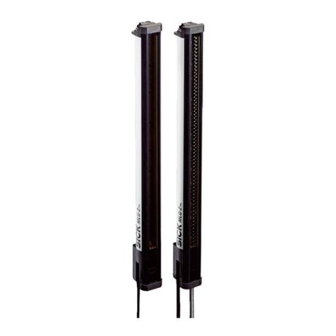
The MLG-2 WebChecker is designed for optical and non-contact edge detection
and width measurement of exible and rigid sheets of material.
Providing no object is located between the sender and receiver, the light beams
from the sender LEDs will hit the receiver LEDs. If an object is located between
the sender and receiver, the light beams will be interrupted, depending on the size
of the object.
Meaning Sender LED Receiver LED Control panel
LED
Supply voltage on Green OGreen O–
Alignment aid active / Alignment
poor
–Yellow Ö3 Hz +
Green O
Alignment Ö
3 Hz
Alignment good/sensor teach-in
good/material teach-in good
–Yellow oAlignment o
Teach-in active – Yellow Ö1 Hz +
Green O
Alignment
Ö1 Hz
At least one light beam interrupted –Yellow O +
Green O
Alignment O
No light beam interrupted – Green OAlignment o
ko
MLG-2 WebChecker는 유연하거나 뻣뻣한 재료 웹의 비접촉식 광학 모서리 감지
및 폭 측정을 위한 제품입니다.
송신기와 수신기 사이에 물체가 없는 동안에는 송신 LED의 광선이 수신 LED에
닿습니다. 송신기와 수신기 사이에 물체가 있으면 물체의 크기에 따라 광선이
끊어집니다.
의미 송신기 LED 수신기 LED 조작 필드 LED
공급 전압 켜짐 초록색 O초록색 O–
정렬 보조 기능 활성/정렬
불량
–노란색 Ö
3Hz +
초록색 O
Alignment Ö
3Hz
정렬 양호/센서 티치인 양호/
재료 티치인 양호
–노란색 oAlignment o
티치인 활성 –노란색 Ö
1Hz +
초록색 O
Alignment
Ö1Hz
적어도 하나의 모서리가 감
지됨
–노란색 O +
초록색 O
Alignment O
모서리가 감지되지 않음 –초록색 OAlignment o
2 Mounting
마운팅
en
1 Align the sender and receiver with each other. Fig. 2.
2 Mount the sender and receiver using the bracket. 5 to 6 Nm. Fig. 3.
– QuickFix bracket (included in the scope of delivery, part no. 2066048)
– FlexFix bracket (optional, part no. 2066614)
– MLG-2 ≤ 2 m: Senders 2 pieces. Receivers 2 pieces.
– MLG-2 > 2 m: Senders 3 pieces. Receivers 3 pieces.
ko
1 송신기와 수신기를 서로 정렬하십시오. 그림 2
2 브래킷을 이용하여 송신기와 수신기를 마운팅하십시오. 5Nm ~ 6Nm. 그림 3.
– QuickFix 브래킷(공급 범위)(품목 번호 2066048)
– FlexFix 브래킷(옵션)(품목 번호 2066614)
– MLG-2 ≤ 2m: 송신기 2개. 수신기 2개.
– MLG-2 > 2m: 송신기 3개. 수신기 3개.
Fig. 2 / 그림 2
max. 2.5 m
8026266 // 12.01.2021
8024514:UL Environmental Rating: Enclosure Type 1
2006/42/EC
NO
SAFETY
MLG-2 WebChecker | SICK
Fig. 3 / 그림 3
3 Electrical installation
전기 설치
UB: 18 ... 30 V DC (without load / 무부하 상태
en
Make the electrical connection in a voltage-free state. Ensure the voltage supply is not
connected.
If the supply voltage is connected, the green LED on the sender and receiver will
be visible.
ko
무전압 상태에서 전기 연결 작업을 하십시오. 전원이 차단되었는지 확인하십
시오.
공급 전압이 걸리는 즉시 송신기와 수신기에서 초록색 LED가 켜집니다.
Example / 예
Fig. 4 / 그림 4
1
3
7
4
5
2
6
en
1 Connection between Ethernet and receiver
2 Ethernet connecting cable
3 Receiver connection: voltage supply, inputs, outputs and synchronization
4 T-connector (SBO-02F12-SM1: part no.: 6053172)
5 Connecting cable for PLC or IO-Link eld module (DOL-1208-GxxM)
6 Connection cable (DSL-1205-GxxMC)
7 Sender connection: voltage supply, synchronization and test input
ko
1 수신기 Ethernet 연결부
2 Ethernet 연결 케이블
3 수신기 연결부: 전압 공급, 입력, 출력, 동기화
4 T 피스(SBO-02F12-SM1: 품목 번호: 6053172)
5 PLC 또는 IO-Link 필드 모듈 연결 케이블(DOL-1208-GxxM)
6 연결 케이블(DSL-1205-GxxMC)
7 송신기 연결부: 전압 공급, 동기화, 테스트 입력
MLG-2 sender M12, 5-pin, A-coded
Male connector Pin Signal Description
1
43
5
2
1 L+ 24 V supply voltage
2 Sync_A Synchronization
3 M GND supply voltage
4 Test_In Test input
5 Sync_B Synchronization
MLG-2 receiver M12, 4-pin, D-coded
Female connector Pin Signal Description
1
43
2
1 L+ Ethernet
2 Sync_A Ethernet
3 M Ethernet
4 Test_In Ethernet
MLG-2 receiver with 4 x Q , M12, 8-pin, A-coded [MLGXXW-XXXXRXXXXX]
Male connector Pin Signal Description
1
7
2
6
5
4
3
8
1 L+ 24 V supply voltage
2 Sync_A Synchronization
3 M GND supply voltage
4 Q1/C Switching output 1 with IO-Link
5 Sync_B Synchronization
6 Q2 Switching output or switching input 1
7 Q3 Switching output or switching input
8 Q4 Switching output or switching input 1
1 Congurable
MLG-2 receiver with 2 x QA , M12, 8-pin, A-coded [MLGXXW-XXXXIXXXXX]
Male connector Pin Signal Description
1
7
2
6
5
4
3
8
1 L+ 24 V supply voltage
2 Sync_A Synchronization
3 M GND supply voltage
4 Q1/C Switching output 1 with IO-Link
5 Sync_B Synchronization
6 Q2 Switching output or switching input 1
7 QA1 Analog output 1
8 QA2 Analog output 2
1 Congurable
MLG-2 receiver with RS-485 , M12, 8-pin, A-coded [MLGXXW-XXXXBXXXXX]
Male connector Pin Signal Description
1
7
2
6
5
4
3
8
1 L+ 24 V supply voltage
2 Sync_A Synchronization
3 M GND supply voltage
4 Q1/C Switching output 1 with IO-Link
5 Sync_B Synchronization
6 Q2 Switching output or switching input 1
7 RS485_A RS-485 interface
8 RS485_B RS-485 interface
1 Congurable
MLG-2 receiver with 3 x Q, 1 x QA M12, 8-pin, A-coded [MLGXXW-XXXXGXXXXX]
8026266 // XX.12.2020
2. 센서 티치인
정렬이 성공적으로 끝났습니다.
1 Teach 버튼을 1~5초 누르십시오.
– 수신기의 노란색 LED가 천천히 깜빡입니다(1Hz).
– 조작 필드의 Alignment LED가 천천히 깜빡입니다(1Hz).
2 송신기와 수신기 사이에서 물체를 완전히 제거할 수 없는 경우 SOPAS를 통
해서만 센서 티치인이 가능합니다.
“Teach” 버튼으로 티치인을 실행할 때는 모든 빔이 끊어지지 않은 상태여야
합니다.
3 센서 티치인이 끝날 때까지 기다리십시오.
– 수신기의 노란색 LED와 Alignment LED가 꺼지거나 QoR 알람 때문에 깜
빡입니다(3Hz).
– 센서 티치인 오류: 수신기의 빨간색 LED가 빠르게 깜빡입니다(10Hz).
3. 재료 티치인
송신기와 수신기가 정렬됨. 센서 티치인이 성공적으로 끝났습니다.
1 감지할 모든 물체를 송신기와 수신기 사이에서 올바른 거리에 배치하십시
오. 그림 5 및 표 1.
2 Teach 버튼을 1초보다 짧게 누르십시오.
3 재료 티치인이 끝날 때까지 기다리십시오.
– 수신기의 노란색 LED와 Alignment LED가 켜짐
(적어도 하나의 모서리가 감지됨)
– 재료 티치인 오류: 수신기의 빨간색 LED가 빠르게 깜빡임(10Hz)
Fig. 5 / 그림 5
ca. 2/3ca. 1/3
max. 2.5 m
Tab. 1 / 표1
Distance between
sender and
receiver / 송신기 –
수신기 거리
Optimal distance
between object and
sender / 물체와 송
신기의 최적 거리
Optimal distance
between object and
sender / 물체와 송
신기의 최적 거리
Optimal distance
between object and
receiver / 물체와
수신기의 최적
거리
mm % mm mm
200 73.4 146.8 53.2
250 72.1 180.3 69.8
300 71.1 213.3 86.7
400 69.8 279.2 120.8
500 69.1 345.5 154.5
600 68.6 411.6 188.4
700 68.3 478.1 221.9
800 68.1 544.8 255.2
900 68.0 612.0 288.0
1000 67.8 678.0 322.0
1100 67.7 744.7 355.3
1200 67.7 812.4 387.6
1300 67.6 878.8 421.2
1400 67.5 945.0 455.0
1500 67.4 1011.0 489.0
1600 67.3 1076.8 523.2
1700 67.3 1144.1 555.9
1800 67.2 1209.6 590.4
1900 67.1 1274.9 625.1
2000 67.0 1340.0 660.0
2100 67.0 1407.0 693.0
2200 66.9 1471.8 728.2
2300 66.8 1536.4 763.6
2400 66.7 1600.8 799.2
2428 66.7 1619.5 808.5
2500 66.6 1667.5 823.5
Male connector Pin Signal Description
1
7
2
6
5
4
3
8
1 L+ 24 V supply voltage
2 Sync_A Synchronization
3 M GND supply voltage
4 Q1/C Switching output 1 with IO-Link
5 Sync_B Synchronization
6 Q2 Switching output or switching input 1
7 Q3 Switching output or switching input 1
8 QA Analog output
1 Congurable
4 Commissioning
커미셔닝
en
We recommend commissioning the MLG-2 WebChecker using the conguration
software SOPAS Engineering Tool (ET) available at www.sick.com. Commissioning
using the Teach pushbutton is described in the following.
The alignment aid on the MLG-2 is only available one time for initial commission-
ing. If the MLG-2 has to be realigned, you must do so using SOPAS ET.
1. Alignment
No object between sender and receiver.
The alignment aid is active. The yellow LED on the receiver ashes quickly (3 Hz).
1 Align the receiver with the sender.
– Alignment poor: The yellow LED on the receiver and the Alignment LED
ashes quickly.
– Alignment good: The yellow LED on the receiver and the Alignment LED are
off.
2 Fix the sender and receiver in place.
2. Sensor teach-in
Alignment was successful.
1 Press the Teach pushbutton for 1 s to 5 s.
– The yellow LED on the receiver ashes slowly (1 Hz).
– The Alignment LED on the control panel ashes slowly (1 Hz).
2 If the object cannot be completely removed between the transmitter and
receiver, sensor teach-in is only possible via SOPAS. If the Teach-In is carried
out using the “Teach” button, all beams must be free.
3 Wait until sensor teach-in is complete.
– The yellow LED on the receiver and the Alignment LED are off or are ashing
(3 Hz) due to the QoR alarm.
– Sensor teach-in error: The red LED on the receiver ashes quickly (10 Hz).
3. Material teach-in
Sender and receiver aligned. Sensor teach-in was successful.
1 Place all objects to be detected at the correct distance between the sender
and receiver. Fig. 5 and Tab. 1.
2 Press the Teach pushbutton for less than 1 s.
3 Wait until material teach-in is complete.
– The yellow LED on the receiver and the Alignment LED are on
(at least one edge detected).
– Material teach-in error: Red LED on the receiver ashes quickly (10 Hz).
ko
구성 소프트웨어 SOPAS 엔지니어링 툴(ET)을 이용하여 MLG-2 WebChecker를
커미셔닝할 것을 권장합니다(www.sick.com). 다음은 Teach 버튼을 이용한 커미
셔닝을 설명한 것입니다.
MLG-2의 정렬 보조 기능은 최초 커미셔닝을 위해 한 번만 사용할 수 있습니다.
MLG-2를 다시 정렬해야 하는 경우 SOPAS ET를 이용하여 MLG-2를 정렬해야 합
니다.
1. 정렬
송신기와 수신기 사이에 물체가 없음.
정렬 보조 기능이 활성화되어 있습니다. 수신기의 노란색 LED가 빠르게 깜빡입
니다(3Hz).
1 수신기를 송신기에 맞춰 정렬하십시오.
– 정렬 불량: 수신기의 노란색 LED와 Alignment LED가 빠르게 깜빡입니다.
– 정렬 양호: 수신기의 노란색 LED와 Alignment LED가 꺼집니다.
2 송신기와 수신기를 고정하십시오.
MLG-2 WebChecker | SICK
Process data structure/ 프로세스 데이터 구조
IO-Link version V1.1
Process data length:
32 Byte In
1 Byte Out
Process Data In
Byte 0 1 2 3
Name Output Function 1 Output Function 2
Type UInt16 UInt16
Byte 4 5 6 7
Name Output Function 3 Output Function 4
Type UInt16 UInt16
Byte 8 9 10 11
Name Output Function 5 Output Function 6
Type UInt16 UInt16
Byte 12 13 14 15
Name Output Function 7 Output Function 8
Type UInt16 UInt16
Byte 16 17 18 19
Name Output Function 9 Output Function 10
Type UInt16 UInt16
Byte 20 21 22 23
Name Output Function 11 Output Function 12
Type UInt16 UInt16
Byte 24 25 26 27
Name Output Function 13 Output Function 14
Type UInt16 UInt16
Byte 28 29 30 31
Name Output Function 15 Output Function 16
Type UInt16 UInt16
Process Data Out
Byte 0
Name Process Data Out
Type UInt16
5 Troubleshooting
장애 해결
en
Meaning Sender LED Receiver LED Control panel LED
Supply voltage o or too low All oAll oAll o
Hardware error Red ORed O–
Sensor teach-in or material
teach-in error
–Red Ö10 Hz +
Yellow o +
Green o
Alignment: Ö 10 Hz
RS-485 /
IO-Link: Ö 10 Hz
QoR-alarm – Yellow Ö3 Hz +
Green O
Alignment
Ö3 Hz
Sync error – Red O + Yellow
O
–
Short-circuit – Red O + Green
O
–
Meaning Measure
Supply voltage o or too low Check the supply voltage.
Hardware error Contact Service.
Meaning Measure
Sensor teach-in error Check that the front screens are clean.
Ensure that all light beams are unobstructed during
teach-in.
Check the alignment of the sender and receiver with
each other. Perform alignment again.
Perform sensor teach-in again.
Check “Blanking” in the SOPAS settings in the menu.
Material teach-in error No material is located between the sender and receiver.
The material is transparent.
Check “Blanking” and “Material teach-in” in the SOPAS
settings in the menu.
QoR-alarm Clean the sensor.
Check alignment.
Check the quality of the material
Sync error Check the electrical connection.
Check the electrical cables for breakage.
Short-circuit Contact Service. Replace the device.
ko
의미 송신기
LED 수신기 LED 조작 필드 LED
공급 전압이 꺼짐 또는 너
무 낮음
모두 o모두 o모두 o
하드웨어 결함 빨간색 O빨간색 O–
센서 티치인 또는
재료 티치인 오류
–빨간색 Ö
10Hz + 노란색
o + 초록색 o
Alignment: Ö 10Hz
RS-485 /
IO-Link: Ö 10Hz
QoR 알람 –노란색 Ö3Hz
+ 초록색 O
Alignment
Ö3Hz
동기화 오류 –빨간색 O + 노
란색 O
–
단락 –빨간색 O + 초
록색 O
–
의미 조치
공급 전압이 꺼짐 또는 너
무 낮음
공급 전압을 점검하십시오.
하드웨어 결함 서비스에 연락하십시오.
센서 티치인 오류 전면창이 깨끗한지 점검하십시오.
티치인 중에 모든 광선이 끊어지지 않도록 확
인하십시오.
송신기와 수신기가 서로 잘 정렬되었는지 점
검하십시오. 정렬을 다시 실행하십시오.
센서 티치인을 다시 실행하십시오.
SOPAS의 "블랭킹" 메뉴에서 설정을 점검하십
시오.
재료 티치인 오류 송신기와 수신기 사이에 물체가 없습니다.
재료가 투명합니다.
SOPAS의 "블랭킹" 메뉴 및 "재료 티치인" 메뉴
에서 설정을 점검하십시오.
QoR 알람 센서를 청소하십시오.
정렬 상태를 점검합니다.
재료 품질 점검
동기화 오류 전기 연결을 점검하십시오.
전기 케이블의 단선 여부를 점검하십시오.
단락
서비스에 연락하십시오. 장치를 교체하십시오.

Other manuals for WebChecker MLG-2

6

Other SICK Measuring Instrument manuals

SICK Lector85x User manual

SICK

SICK Lector85x User manual

SICK VMS4100 User manual

SICK

SICK VMS4100 User manual

SICK GM700 User manual

SICK

SICK GM700 User manual

SICK HTF18 User manual

SICK

SICK HTF18 User manual

SICK LFP CUBIC User manual

SICK

SICK LFP CUBIC User manual

SICK NAV-LOC User manual

SICK

SICK NAV-LOC User manual

SICK S100 Standard User manual

SICK

SICK S100 Standard User manual

SICK MARSIC300 Manual

SICK

SICK MARSIC300 Manual

SICK DEFOR Operating instructions

SICK

SICK DEFOR Operating instructions

SICK FLOWSIC550 User manual

SICK

SICK FLOWSIC550 User manual

SICK FLOWSIC500 User manual

SICK

SICK FLOWSIC500 User manual

SICK WTB4S-3 User manual

SICK

SICK WTB4S-3 User manual

SICK MLG-2 Pro User manual

SICK

SICK MLG-2 Pro User manual

SICK PowerCEMS100 User manual

SICK

SICK PowerCEMS100 User manual

SICK DL100 Pro User manual

SICK

SICK DL100 Pro User manual

SICK EuroFID User manual

SICK

SICK EuroFID User manual

SICK FLOWSIC600 User manual

SICK

SICK FLOWSIC600 User manual

SICK GM901 User manual

SICK

SICK GM901 User manual

SICK nanoScan3 I/O User manual

SICK

SICK nanoScan3 I/O User manual

SICK deTec2 Core User manual

SICK

SICK deTec2 Core User manual

SICK InspectorP64 Series User manual

SICK

SICK InspectorP64 Series User manual

SICK GM901 User manual

SICK

SICK GM901 User manual

SICK UE 4100 User manual

SICK

SICK UE 4100 User manual

SICK VICOTEC450 User manual

SICK

SICK VICOTEC450 User manual

Popular Measuring Instrument manuals by other brands

Antsig AP9000 Installation and operating instructions

Antsig

Antsig AP9000 Installation and operating instructions

Vanguard Instruments Company IRM-5000P user manual

Vanguard Instruments Company

Vanguard Instruments Company IRM-5000P user manual

Team SWR-1180 KA Operating	 instruction

Team

Team SWR-1180 KA Operating instruction

GF Signet 4150 operating instructions

GF

GF Signet 4150 operating instructions

Kipp & Zonen CGR 4 instruction manual

Kipp & Zonen

Kipp & Zonen CGR 4 instruction manual

RF Standard RS-232 user manual

RF Standard

RF Standard RS-232 user manual

Fraser EX715 operating instructions

Fraser

Fraser EX715 operating instructions

Drawell DV-8000 Series user manual

Drawell

Drawell DV-8000 Series user manual

Hanna Instruments HI 717 manual

Hanna Instruments

Hanna Instruments HI 717 manual

Geokon 4422 instruction manual

Geokon

Geokon 4422 instruction manual

Burkert MassFlowMeter 8700 operating instructions

Burkert

Burkert MassFlowMeter 8700 operating instructions

Leuze electronic AMS 3xxi Short description

Leuze electronic

Leuze electronic AMS 3xxi Short description

Metrohm 930 Compact IC Flex ChS/PP/Deg Manual - Short Instructions

Metrohm

Metrohm 930 Compact IC Flex ChS/PP/Deg Manual - Short Instructions

Valhalla 2300 Operation manual

Valhalla

Valhalla 2300 Operation manual

AEMC 6292 Service and calibration manual

AEMC

AEMC 6292 Service and calibration manual

HP 85662A Troubleshooting and repair manual

HP

HP 85662A Troubleshooting and repair manual

janitza UMG 509 Operation manual and technical data

janitza

janitza UMG 509 Operation manual and technical data

DeFelsko PosiTector 200 Reference

DeFelsko

DeFelsko PosiTector 200 Reference

manuals.online logo
manuals.online logoBrands
  • About & Mission
  • Contact us
  • Privacy Policy
  • Terms and Conditions

Copyright 2025 Manuals.Online. All Rights Reserved.