Siebeck JET 2000 RBM User manual

Translation of the original operating manual
Nr.: rbm_bed_0910
JET 2000 tying machine
Model JET - RBM
GMBH D - 69412 EBERBACH
Telephone +49(0)6271 / 9208 0 Fax +49(0)6271 / 9208 88

Siebeck GmbH 0perating manual rbm-bed-0910
Page 2
Table of contents
Page
Hazard warnings…………………………………………………………. 3
Introduction……………………………………………………………….. 4
Warranty…………………………………………………………………… 5
EC declaration of conformity……………………………………………. 6
Technical data / Proper use…………………………………………….. 7
Safety…………………………………………………………………........ 8
Set-up and commissioning.……………………………………………… 9
Inserting the string.…………………………………………………………10
Correct positioning of the products to be tied up…………… 11
Cleaning and maintenance……………………………………………… 12
Operating controls..………………………………………………………..13
Checking the safety mechanism (enabling)…………………… 14
Setting the aggregate’s zero postion…………………………………….15
Setting the stripper…………………………………………………………16
The story of knots.…………………………………………………………17-18
Faults and their causes..…………..……………………………………….19
Residual risks and incorrect operation……………………………………20-21
Spare parts list
Circuit diagrams

Siebeck GmbH 0perating manual rbm-bed-0910
Page 3
Hazard warnings
Hazard warnings are found in the respective position in the text.
They are denoted by this warning
triangle and an information text.
Caution!
The technical manual must have been read and understood
before using the machine for the first time. For personal
safety it is important to follow all the instructions listed in it.
The manual must be kept by the customer and must be
handed over in case the machine is passed ontothird parties
or a new user.
Caution!
Installation and repair must only be performed by qualified
persons who have the necessary experience and
knowledge of occupational and industrial safety and risks of
accidents. If the available staff do not have one or more of
these qualifications, specialist staff must be contracted.
Caution!
If it is necessaryto replace a components, you must
make sure that only original spare parts are used.
Improper repairs or the use of non-original spare parts
can cause considerable damage and hazards for the
user.
In case of damage which has be caused by failure to observe this operating
manual, the warranty will be rendered null and void. No liability will be
assumed for consequential damages.
No liability will be assumed in case of material damages or personal injuries
which are caused by improper use or failure to adhere to the safety
instructions.

Siebeck GmbH 0perating manual rbm-bed-0910
Page 4
Introduction
This machine has been engineered in accordance with the recognised rules
of technology and in adherence to the regulations for occupational safety and
the prevention of accidents so that proper use cannot not cause any
hazards for the life and limb of the user or third parties.
Information on incorrect use and residual risks, which are still in place or
possible despite the integrated safety and technical protective
equipment, are described and illustrated on pages 20 - 21. These risks are
documented in a risk analysis and filed by the manufacturer.
Every person on the user's premises given the task of
setting up, commissioning, operating, maintaining and
repairing this machine must have read and understood
this operating manual, and in particular the chapter
"Safety".
The customer's own changes, restrictions or upgrades and the resultant
safety-related consequences are at the expense and risk of the user.
If this machine is sold or set up at another location, this
operating manual must be handed over to the new owner or the
new user. Additional copies can be ordered from the address
given below, quoting article number rbm_bed_0910.
D-69412 Eberbach, Germany
Telephone +49 (0)6271 9208 0
Fax +49 (0)6271 9208 88
E-mail : info@siebeck.de
Internet : www.siebeck.de

Siebeck GmbH 0perating manual rbm-bed-0910
Page 5
WARRANTY
All machines which have been manufactured at our production
facilities are covered by a warranty of 12 months, starting from
the date of commissioning, or 18 months from the date of delivery.
This warranty covers material and manufacturing faults.
The warranty covers all parts, with the exception of
expendable parts and parts which are replaced due to normal
wear during maintenance. Under the terms and conditions of
the warranty we are not liable for working hours and downtimes.
If machine damage is caused due to the use of
unsuitable tying material or material not expressly recommended
by us, the warranty will be rendered null and void.
Where any damage or loss is caused through non-adherence to
this operating manual, any warranty claims shall be null and void.
No liability shall be accepted for any consequential losses.
Where material damage or personal injury is caused through
improper use or failure to follow safety advice, no liability shall be
accepted.
All claims must be asserted in writing. An exact description of the
cause of damage, the part number and machine number must be
enclosed. Once we have accepted your warranty claim, the
faultypart must be returned to us.
This warranty is only valid if original parts
without any form of modification are used.

Siebeck GmbH 0perating manual rbm-bed-0910
Page 6
EC declaration of conformity
We hereby declare that the machine described as follows
Manufacturer : SIEBECK
Model : JET - RBM
Serial No. :
,in its delivered condition, complies with the following valid
stipulations:
EG Machinery Directive 2006/42/EG (valid from 28.12.2009)
Applied harmonised standards, in particular
EN ISO 12100 Part 1 & 2 "Safety of Machinery"
EN 60204-1 "Electrical Equipment of Machines"
89/336/EEC including amendments from 92/31/EEC
"EMC Guideline"
Eberbach, 10.06.09
Siebeck GmbH

Siebeck GmbH 0perating manual rbm-bed-0910
Page 7
Technical data
Machine dimensions:
315
850
I
2210 750
120
560
965
D - 6 9 4 12 EB E R BA C H
850
510
135 135
All dimensions are in mm, subject to changes
Connected electrical load: 400 Volt, 3 phase alternating current, 1 kW, 50 Hz
Machine performance: 40 cycles p. min.
Machine weight: 210 kg
Noise pressure level: < 79 dB(A) as per EN 11204
(without product / without string)
Proper use:
Tying string around preferably circular products
AB
C
Ring dimensions
max. min.
A
B
C
1100 mm 100 mm
1000 mm 100 mm
315 mm 5 mm
Siebeck GmbH 0perating manual rbm-bed-0910
Page 8
Safety
The European standard EN 60204-1 requires the power
supply connection to be established by a suitable plug
device. The power supply cable must not be connected to a
power distributor directly by way of a terminal connection,
without a plug connector.
Safety limit switch S1 prevents the machine from starting up
when the machine hood is open. This safety device must be
checked before putting the machine into operation each
time to make sure it is fully functional.
Procedure:
First switch on the machine and wait for the reference run to be performed
(see last paragraph below), open the hood, do not reach into the machine
(!), then press the foot pedal. The machine must not start up.
Caution! Risk of crushing! Checking the safety mechanism
During downward movement, the RBM-10-310 toothed rack has an electro-mechanical
safeguard. If the RBM-10-220 needle shoe touches any object above the worktop, the
drive motor gets immediately reversed and the rack moves up into the starting position.
To check this safety mechanism, lay a sheet of paper over the worktop opening. Now
start the machine by pressing the pedal. If this process damages the sheet of paper, the
safety mechanism needs checking (see procedure on page 12). The manufacturer
recommends performing this test on a daily basis.
Always pull the mains plug before maintenance and cleaning
work!
When inserting a new string bobbin, and when threating the
string, always pull the mains plug.
A minimum of 500 lux is required for local lighting.

Siebeck GmbH 0perating manual rbm-bed-0910
Page 9
Set-up and commissioning
Erect the machine in the designated location and press the wheel locks
down so that the machine is stable.
To avoid collisions with other machines and to ensure operating
and maintenance staff have sufficient access, there must be
minimum of 1.5 metres of clearance around the entire machine.
If not otherwise stipulated, the machine is designed for 230 V 1-phase
alternating current 50/60 Hz when supplied from the factory. Measure
the local mains voltage and compare the measurement with the value
specified on the type plate.
Check that the machine is correctly grounded. Adhere to the local
electrical engineering regulations. Maximum fuse protection 16
amperes. Connect the machine to the supply mains using a plug
connector. Switch on the master switch. The indicator lamp lights
up.
Checking the motor's rotary direction
The machine is fitted with a device to monitor the direction of rotation
(phase sequence relay).
Using the mains plug, connect the machine to the electricity mains. Turn
on main switch. After c. 5 seconds the control light glows solidly, thus
signalising that the direction of rotation is correct. The machine is ready for
use.
If the control light does not come on, the phase sequence is wrong. The
monitoring device cuts off the supply of electricity. For the correct direction
of rotation you need to switch two phase lines inside the mains plug.
Tying material
The knotting mechanism is designed for a maximum material thickness of
900 linear metres per kilogram (ELA-900). It is recommended that during
the warranty period you purchase the material from the machine
manufacturer. This avoids any potential loss of your right to make a
warranty claim that incorrect material use may cause.
Siebeck GmbH 0perating manual rbm-bed-0910
Page 10
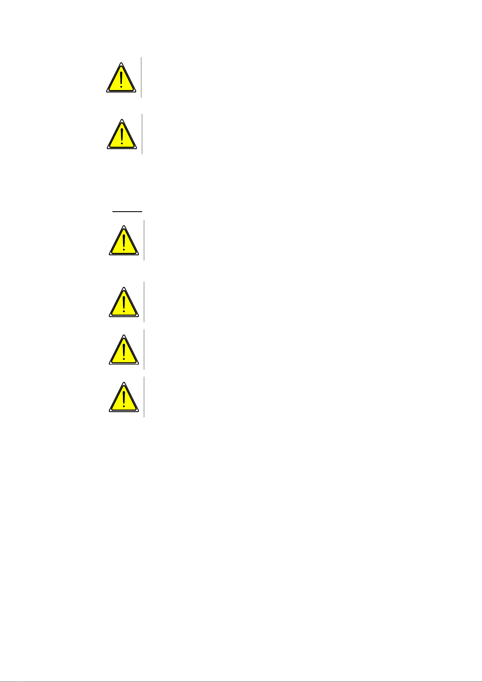
Inserting the string
I
B
A
C D E
F
E
F
1
2
3
4
5
G
1- 5
G
HH
1. Insert the string bobbin into the string container (A) and press
firmly against the foam rubber pad (B).
2. Feed string through the hole (C) in the flat bar, under the brake
plate (D) and through the hole (E).
3. Feed through between the brake bracket and brake plate (F).
4. Thread from front to back into the five string rollers, starting at 1
and in sequence up to 5, and then through the hole (G) in the
needle arm.
5. Using your right hand, pull the end of the string further up to the
right, rear corner of the worktop and secure it there.
6. Actuate machine (after enabling it as described on page 14) via
the foot pedal. The string then gets automatically deployed under
the worktop and cut off.
Caution, risk of crushing!
The opening in the middle of the worktop must be kept clear!
When the needle dips in, there is a significant risk of injury
here.

Siebeck GmbH 0perating manual rbm-bed-0910
Page 11
Correct positioning of the products to be tied up
1. For the first and each subsequent binding the products to be
tied up should be fed until over the guide edge marked on the
worktop (see illustration below).
2. After the first binding, the products get fed further to the right
and once again until nearly over the guide edge.
Should tying up the product twice not suffice, the process
needs to be repeated.
3. If the product gets pushed beyond the guide edge, the binding
will be loose. If the product gets fed just short of the guide
edge, the binding will fail / the string will snap.
Kordel
Anlegekante
Anlegekante
Kordel
Anlegekante
Anlegekante
Nadelarm Nadelarm
Tischplatte Tischplatte

Siebeck GmbH 0perating manual rbm-bed-0910
Page 12
Cleaning and maintenance
Um Unfälle beim Reinigen und Abschmieren der Maschine zu
vermeiden, ist unbedingt darauf zu achten, daß der
Hauptschalter ausgeschaltet, bzw. die Maschine stromlos ist.
Der Hersteller der Maschine ist von jeglicher Haftung
entbunden, wenn diese zwingende Vorschrift nicht beachtet
wird.
Reinigen der Maschine
Nach einer Betriebszeit von ca. 40 Arbeitsstunden ist die
Maschine gründlich zu reinigen. Die Tischplatte muss
abgenommen werden, damit das Knoteraggregat offen liegt und
leicht gereinigt werden kann. Reinigung nur mit einem
Staubsauger vornehmen. Keine Druckluft einsetzen.
Schmierplan
Nach einer Betriebszeit von ca. 40 Arbeitsstunden sind alle
Schmiernippel abzuschmieren (nur Öl, kein Fett verwenden). Alle
Schmierstellen, die mit roter Farbe gekennzeichnet sind, müssen
zweimal wöchentlich mit einer Ölkanne abgeschmiert werden.
Alle beweglichen Teile müssen einmal wöchentlich geölt werden.
Siebeck GmbH 0perating manual rbm-bed-0910
Page 13
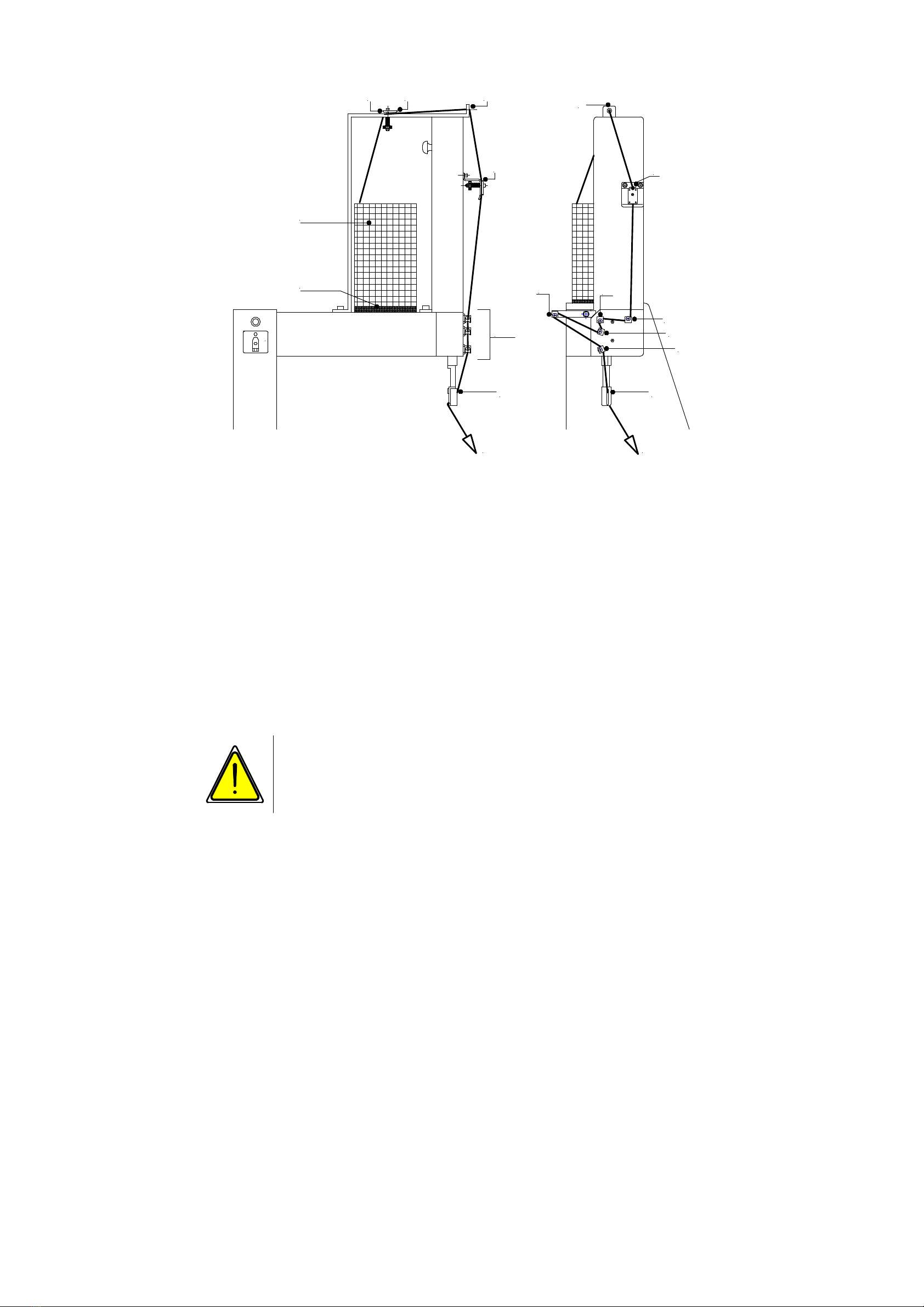
Operating controls
I
1
2
34
1 Control light
- On solidly = ready for use
- Flashing = enable
(see page ...)
2 Main switch = O / Off I / On
3 Toggle switch
- Position 1 = ready for use
- Position 2 = aggregate motor brake
released
- Position 3 = needle motor brake released
4 Push button
(under worktop in front of aggregate motor)
- Press repeatedly= move aggregate forwards
step by step
- Press continuously = aggregate moves forward
into zero position
Jog mode operation via push button:
Only authorised and traind staff is allowed to perform this
prozedure!

Siebeck GmbH 0perating manual rbm-bed-0910
Page 14
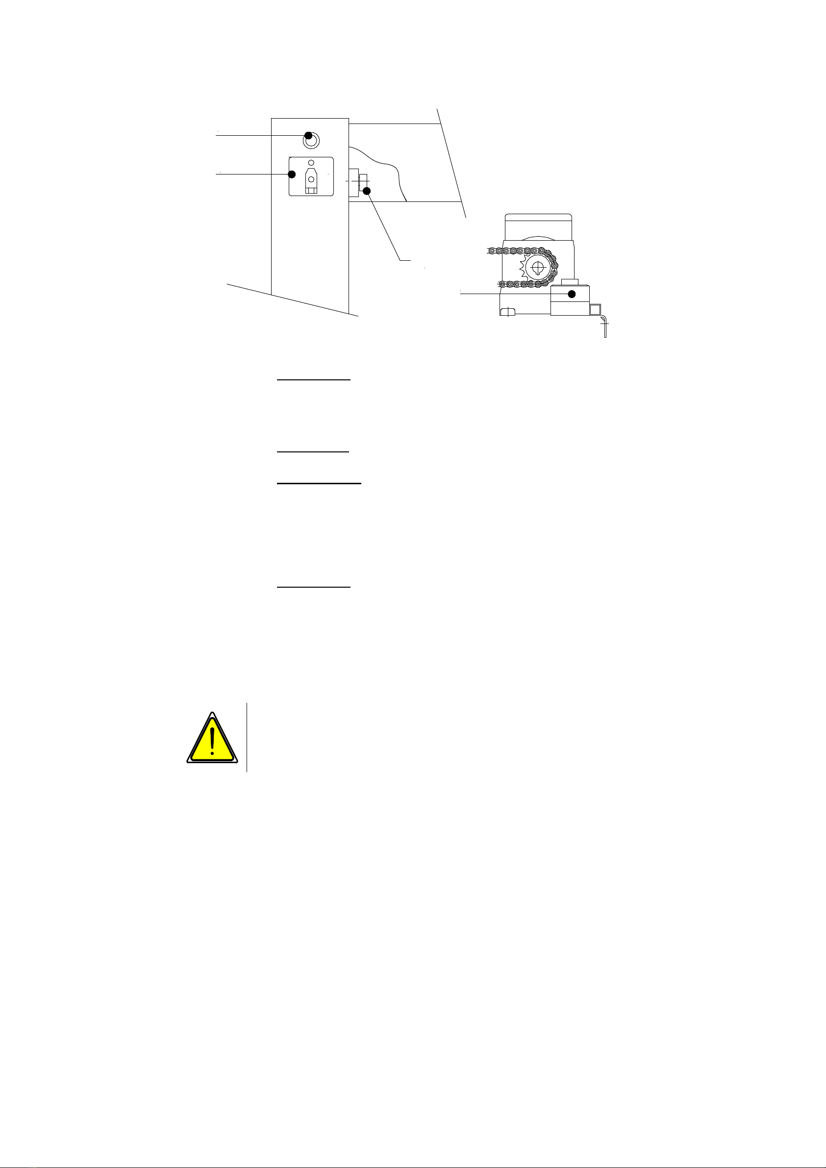
Checking the safety mechanism
(Enabling)
Caution!
Risk of crushing!
During downward movement, the RBM-10-310 toothed rack
has an electro-mechanical safeguard. If the RBM-10-220
needle shoe touches any object above the worktop, the drive
motor gets immediately reversed and the rack moves up into
the starting position.
After switching on, the machine's start-up is blocked. This block
also becomes automatically active if the machine is not used for
over an hour. This start-up block is indicated by a flashing a
control light.
In order to enable the machine, you need to push the (yellow)
RBM-10-220 needle shoe gently with your flat palm up as far as it
will go and then let go again. Do not use any force! The needle
shoe must allow itself to be pushed up easily and automatically go
back to the starting position.
This procedure checks every element of the integrated safety
mechanism. If all is functioning properly, the machine gets
enabled. The control light glows solidly and the machine is ready
for use.
If the machine does not get enabled, the following checks should
be made:
1. Switch off machine.
2. Unscrew covering panel on the needle arm.
3. Check that the needle shoe moves easily. If necessary, clean
and oil.
4. Check that the RBM-10-470 securing plate is firmly in place.
5. Check that the RBM-50-030 monitoring switch is firmly in place
and working properly both electrically and mechanically.
6. Check that the RBM-10-210 contact is at the correct distance
from limit switch lever and firmly in place.
7. Check that the RBM-10-290 adjusting collar is firmly in place.
Only authorised and traind staff is allowed to perform this
chec-up!

Siebeck GmbH 0perating manual rbm-bed-0910
Page 15
Setting the aggregate’s zero position
JAG-07-050
S7
S3
"O"
The correct zero position ('O') is when the JAG-07-050 injector lever has
reached its extreme left position.
You adjust the zero position by moving the S7 limit switch.
Only authorised and traind staff is allowed to perform this
adjustement!

Siebeck GmbH 0perating manual rbm-bed-0910
Page 16
Stripper setting
The side setting for the stripper "C" is made using the threaded pin No. 9
(group M4).
When the knotter "A" moves back, stripper "C" must rest on knotter "A"
with pressure.
The height setting is made using the toggle link socket No. 2 (group M4).
The correct height of the stripper slot "B" to the knotter is shown in the
figure below.
A
B C
Only authorised and traind staff is allowed to perform this
adjustement!

Siebeck GmbH 0perating manual rbm-bed-0910
Page 17
The story of knots
Incorrect knotting
patterns and their
causes
Short loops
The knotter opens too early. Shift the mount for
the cam roller for opening the knotter backwards
towards the chain wheel. The stripper does not
rest on the knotter. The string is too thin.
Knots not strong enough
Stripper slot too large. The knotter opens too
early. The string is too thin.
String not cut cleanly
The string knife is blunt. Flip or replace the knife.
String break before the knot
Sharp edges on the stripper, drawslide head, tip
up lever or knife lever.

One loop of normal length, one loop which is too short
The knotter is not closing properly. Tension
spring for the knotting lock is too weak. The
stripper does not rest on the knotter.
Single loop
The knot has only a single loop. The second
loop is drawn through. Increase the spring
pressure on the twine button. The lead end of
the string which protrudes from the twine button must not move when the
tying arm starts up.
Loop ends torn
Upper or lower finger of knotter or stripper has
sharp-edges.
The perfect knot
A correct knot has two loops of equal
length and one short and one long end of
string. The knot is tight and hard.
Siebeck GmbH Operating manual rbm_bed_0910
Page 19
Faults and their causes
Never rework the surface of the twine button housing! This
surface has an exactly specified contour. The notch is
intentional and has not been created by wear. Only ever
make the necessary settings by adjusting the string brake and
twine button spring.
1. Threading: Make sure that threading has been performed
properly.
The string taking the wrong course is the most common cause of
string breaks (see "Inserting the string" on page 10).
2. String: The machine is set to a certain string thickness.
Always use the same quality and thickness of string in order to achieve
the best results.
a) String which is too weak often breaks on the twine
button instead of being pulled out without hindrance
b) If the string is too thick, it will not be released by the
knotter
c) String which is too thin causes a loose knot
3. Twine button: If you are using a good quality of string of the
correct thickness and it still breaks and leaves behind residual fibres in
the twine button, this is generally caused by excessive spring tension on
the twine button.
Reduce the spring tension. Make sure that the setting wheel re-
engages properly and the retainer screw is tightened.
4. String tension: You achieve the best results with an even,
smooth string brake setting. Check the setting by pulling out a few
metres of string from the tying arm tube. You can change the string
tension by turning the knurled nut on the string brake.
Every person on the user's premises given the task of
setting up, commissioning, operating, maintaining and
repairing this machine must have read and understood
this operating manual, and in particular the chapter
"Safety".

Siebeck GmbH Operating manual rbm_bed_0910
Page 20
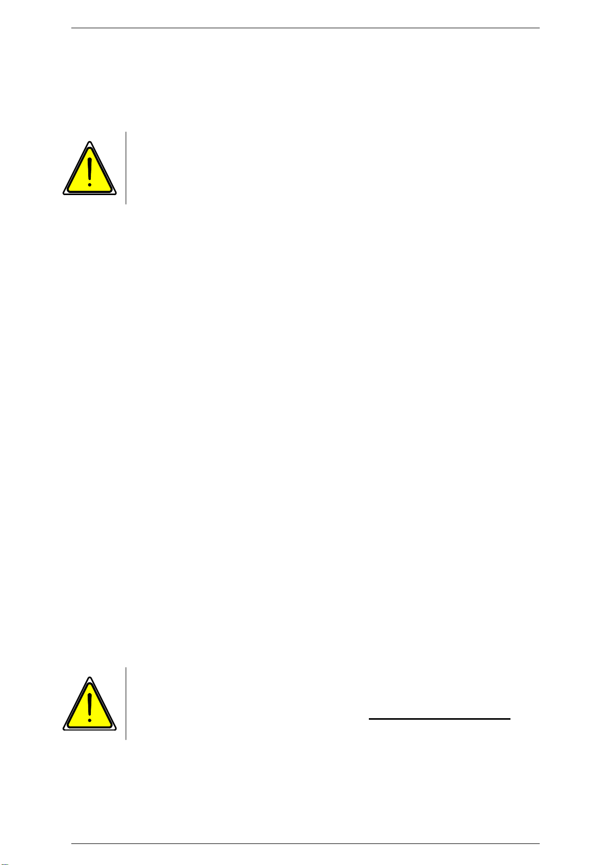
Residual risks and incorrect operation
Residual risks and incorrect operation which exist despite measures for
integrated safety and technical protective equipment, are described and
illustrated in the following. These risks are documented in a risk analysis
and filed by the manufacturer.
With the worktop unscrewed, it is possible to advance the knotting
aggregate step by step via the push button (jog mode). The individual
movement processes can thus be well observed.
Jog mode:
Only authorised and trained staff is allowed to
perform this procedure.
In the entire area of the knotting aggregate, in particular on its
drive elements, between the chain wheel and roller chain , and
between the trigger and the frame, there is a considerable
risk of crushing.
Caution, risk of crushing!
The opening in the middle of the worktop must be kept clear!
When the needle dips in, there is a significant risk of injury
here.
Thermal hazard!
The drive motors M can reach temperatures of up to 80°C.
When the sections of panelling are removed, contact can
cause injuries.
Table of contents
Other Siebeck Packaging Equipment manuals


Popular Packaging Equipment manuals by other brands


AirSaver
AirSaver F2 Safety instructions, setup & installation manual

HUALIAN
HUALIAN M-PE Series Operation manual

Pro Pack Solutions
Pro Pack Solutions Eagle 710 Operation manual

Oliver
Oliver 1808-D User's operation

Kronos
Kronos H-46 Series Operation, safety and spare parts manual

Robopac
Robopac ROBOT S7 Use and maintenance manual