Siebeck JET 2000 Operational manual

Translation of the original
operating manual
No. jet_in_bed_0315
Strapping machine JET 2000
Model JET IN
D - 69412 EBERBACH
ElektischerAnschlußwert Electricalsupply
KW
Volt Hz
Machinetype
Maschinentyp
Maschinen-Nr.
Machine-N°
Baujahr
Yearof constr.
Maschinenbez.
Masch.gewicht
Machineweight
Machinename
Verschnürungsmaschine/ Tyingmachine
Ph.AC
Internet:www.siebeck.de email:[email protected]
1
0
GMBH D - 69412 EBERBACH
Telephone 00496271-92080 Fax 00496271-920888

Siebeck GmbH Translation of the original operating manual jet_in_bed_0315
Seite 2
Table of contents
Page
Hazard warnings ………………………………………………………… 3
Foreword……………………………………………………………………4
Warranty…………………………………………………………………….5
EC Conformity declaration ………………………………………………..6
Technical data
Proper use ……………………………………….. 7
Safety…………………………………………………………………... 8
Set-up and commissioning ...………………………………………… 9
Inserting the string …………………………………………………….. 10
Correct positioning of the products to be wrapped……………… 11
Maintenance and care…………………………………………………… 12
Operating controls ……………………………………………………… 13
Aggregate zero point setting ………………………………………….. 14
Setting the stripper …………………………………………………….. 15
The story of knots ………………………………………………………. 16-17
Faults and their causes …… ………………………..………………….18
Residual risks and incorrect operation …………………………………19-20
Spare parts – list
Wiring and circuit plan

Siebeck GmbH Translation of the original operating manual jet_in_bed_0315
Seite 3
Hazard warnings
Hazard warnings are found in the respective position in the text.
They are denoted by this warning triangle and an
information text
Caution!
The technical manual must have been read and understood
before using the machine for the first time. For personal safety it
is important to follow all the instructions listed in it. The manual
must be kept bythe customer and must be handed over in case
the machine is passed on to third parties or a new user.
Caution!
Installation and repair must only be performed by qualified
persons who have the necessary experience and knowledge of
occupational and industrial safety and risks of accidents. If the
available staff do not have one or more of these qualifications,
specialist staff must be contracted.
Caution!
If it is necessary to replace a component, you must make
sure that only original spare parts are used. Improper repairs
or the use of non-original spare parts can cause
considerable damage and hazards for the user
In case of damage which has be caused by failure to observe this operating
manual, the warranty will be rendered null and void. No liability will be
assumed for consequential damages.
No liability will be assumed in case of material damages or personal injuries
which are caused by improper use or failure to adhere to the safety
instructions.

Siebeck GmbH Translation of the original operating manual jet_in_bed_0315
Seite 4
Introduction
This machine has been engineered in accordance with the recognised rules
of technology and in adherence to the regulations for occupational safety and
the prevention of accidents so that proper use cannot not cause any
hazards for the life and limb of the user or third parties.
Information on incorrect use and residual risks, which are still in place or
possible despite the integrated safety and technical protective
equipment, are described and illustrated on pages 43-47. These risks are
documented in a risk analysis and filed by the manufacturer.
Every person on the user's premises given the task of setting
up, commissioning, operating, maintaining and repairing this
machine must have read and understood this operating
manual, and in particular the chapter "Safety".
The customer's own changes, restrictions or upgrades and the resultant
safety-related consequences are at the expense and risk of the user.
If this machine is sold or set up at another location, this
operating manual must be handed over to the new owner or the
new user. Additional copies can be ordered from the address
given below, quoting article number 0914FRT-A-MKIVbed.
Friedrichsdorfer Landstrasse 65
D - 69412 Eberbach
Telephone 0049 6271-92080
Fax 00496271-920888
Internet: www.siebeck.de

Siebeck GmbH Translation of the original operating manual jet_in_bed_0315
Seite 5
WARRANTY
All machines which have been manufactured at our production
facilities are covered by a warranty of 12 months, starting from the
date of commissioning, or 18 months from the date of delivery. This
warranty covers material and manufacturing faults.
The warranty covers all parts, with the exception of
expendable parts and parts which are replaced due to normal wear
during maintenance. Under the terms and conditions of the
warranty we are not liable for working hours and downtimes.
If machine damage is caused due to the use of unsuitable tying
material or material not expressly recommended by us, the warranty
will be rendered null and void.
All claims must be asserted in writing. An exact description of the
cause of damage, the part number and machine number must be
enclosed. Once we have accepted your warranty claim, the faulty
part must be returned to us.
This warranty is only valid if
original parts without any form of modification are used.

Siebeck GmbH Translation of the original operating manual jet_in_bed_0315
Seite 6
EC - Declaration of conformity
We hereby declare that the following specified machinery
Make : SIEBECK
Model : JET IN
Serial No. :
complies with the following provisions applying to it:
EC Machinery Directive 2006/42/EC (valid from 29.12.2009)
Harmonised standards applied, in particular
EN ISO 12100 Part 1 and 2 ”Safety of machinery"
EN 60204-1 “Electrical equipment of machines"
89/336/EEC as amended 92/31/EEC “EMC Directive“
Eberbach, date 10.09.2014
Siebeck GmbH

Siebeck GmbH Translation of the original operating manual jet_in_bed_0315
Seite 7
Technical data
Machinery dimensions
D - 69412 EBERBACH
ElektischerAnschlußwert E lectricalsupply
KW
Volt Hz
Machinetype
Maschinentyp
Maschinen-Nr.
Machine-N°
Baujahr
Yearofconstr.
Maschinenbez.
Masch.gewicht
Machineweight
Machinename
Verschnürungsmaschine/ Tyingmachine
Ph.AC
Internet:www.siebeck.de email:[email protected]
SEW
1
0
122,5 - 222,5
450,0
275,0
1575,0 - 1675,0
310,0
2450,0 - 2550,0
250,0
560,0
850,0 - 950,0 410,0
690,0
200,0
105,0
120,0
All dims. in mm, changes reserved
Electrical connection values: 400 Volt, 3 phase power supply, 1 kW, 50 Hz
Machine performance: up to 40 cycles p. min. (based on product size)
Machine weight: 130 kg
Noise pressure level: < 79 dB(A) as per EN 11204
(without product / without string)
Proper use:
Solely commercial / strapping of preferably ring-shaped products
RING DIMENSIONS
AB
C
Ringabmessungen
maximal minimal
A
B
C
600 mm 80 mm
500 mm 70 mm
400 mm 5 mm

Siebeck GmbH Translation of the original operating manual jet_in_bed_0315
Seite 8
Safety!
The European standard EN 60204-1 requires the power supply
connection to be established by a suitable plug device. The
power supply cable must not be connected to a power distributor
directly by way of a terminal connection, without a plug
connector.
The safety limit switch below the table top prevents the machine
from starting up during maintenance work. This safety device
must be checked before putting the machine into operation each
time to make sure it is fully functional.
Procedure:
First switch on the machine and remove table top. Do not reach
into the machine (!), then press the foot pedal. The machine must
not start up.
Attention!
Risk of crushing! Checking protective device
The rack is secured electromechanically during the downward
motion. If the needle shoe hits an object above the table top, the
drive motor is reversed immediately and the rack runs upwards in
the initial position.
To check this protection device, place a box on the table top
opening and start the machine by pressing the foot switch. If the
box is damaged during this process, the protective device must be
checked. The manufacturer recommends carrying out this check
on a daily basis.
Always pull the mains plug before all maintenance and cleaning
work!!
When inserting a new string bobbin, and when threading the
string, always pull the mains plug.
A minimum of 500 lux is required for local lighting.

Siebeck GmbH Translation of the original operating manual jet_in_bed_0315
Seite 9
Set-up and commissioning
Erect the machine in the designated location and press the roller wheel locks
down so that the machine is stable.
To avoid collisions with other machines, as well as for adequate
access for the operating and maintenance personnel, there must
be a clearance of min. 1.5 metres around the machine.
If not otherwise stipulated, the machine is designed for 400 volt 3-phase
alternating current and 50 Hz, when supplied from the factory. Measure the
local mains voltage and compare the measurement with the value specified
on the type plate.
Check that the machine is correctly grounded. Adhere to the local electrical
engineering regulations. Maximum fuse protection 16 amperes.
Checking the motor direction of rotation
The machine comes with a rotation direction monitoring device (phase
sequence relay).
Connect the machine via the mains plug to the mains. Turn on main switch.
If the pilot light does not light up, then there is an incorrect phase sequence.
The monitoring device locks the power supply. Two phase wires must be
exchanged on the mains plug for the correct direction of rotation.
Strapping material
The knotting mechanism is designed for a maximum thickness of 900 linear
metres per kilogram (ELA-900). We recommend obtaining the material from
the machine manufacturer during the warranty period. This prevents the
possible loss of the warranty claim, which could be caused by the incorrect
use of the material.
Siebeck GmbH Translation of the original operating manual jet_in_bed_0315
Seite 10
Inserting the string
D - 69412 EBERBACH
ElektischerAnschlußwert Electrical supply
KW
Volt Hz
Machinetype
Maschinentyp
Maschinen-Nr.
Machine-N°
Baujahr
Year o f co nstr.
Maschinenbez.
Masch.gewicht
Machineweight
Machinename
Verschnürungsmaschine / Tyingmachine
Ph.AC
Internet: www.siebeck.de email: info@sieb eck.de
1
0
BCD A E 21
3
4
5
FG
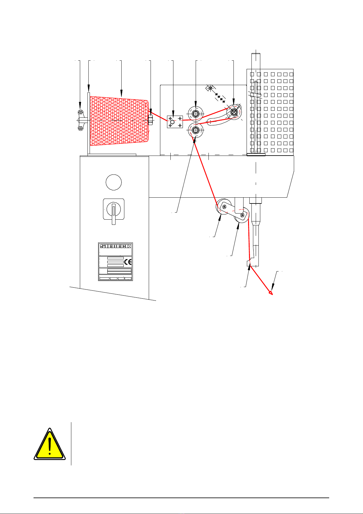
1. Insert bobbin holder (A) with string bobbin (B) into the pick-up (C)
and tighten with wing nut (D).
2. Thread string through between the brake plates (E)
3. Thread into the five string rollers reels starting at 1, and in the
sequence up to 5, and then through the hole (F) in the needle shoe
from top to bottom thread
4. Pull end of string (G) with your right hand as far as the right, rear
table top corner and hold there
5. Start the machine via the foot pedal. The string is then automatically
inserted underneath the table top and cut off
Attention Risk of crushing!
Make sure you keep the opening in the middle of the table top
clear.
When inserting the needle here, there is a considerable risk of
injury.

Siebeck GmbH Translation of the original operating manual jet_in_bed_0315
Seite 11
Correct positioning of the products to be strapped
1. The products to be wrapped (ring) should be run in each case for
the first and any other binding up across the contact surface
marked on the table top (see figure below).
2. After the first binding, the product is run further to the right and
again to just over the contact surface.
If two strappings are not enough, the process must be repeated.
3. If the product is pushed beyond the contact surface, the wrapping
becomes loose. If the product is run just in front of the contact
surface, then there is a fault in the binding, or the string tears.
Kordel
Kordel
Anlegekante
Anlegekante
Nadelschuh Nadelschuh
Tischplatte Tischplatte
Anlegekante
Anlegekante
Ring
Ring
1 2

Siebeck GmbH Translation of the original operating manual jet_in_bed_0315
Seite 12
Service and maintenance of the machine
To prevent accidents when cleaning and servicing the machine, it
is essential to make sure that the main switch is turned off, or the
machine power supply is switched off. The manufacturer of the
machine is released from any liability if this mandatory
requirement is not observed.
Cleaning the machine
After a running time of approximately 40 hours, the machine must be
cleaned thoroughly. The table top must be removed so that the
knotting aggregate is exposed and can be easily cleaned. Clean with
a vacuum cleaner and do not use compressed air.
Lubrication schedule
After a running time of approximately 40 hours, all lubrication nipples
must be lubricated (use only oil, no grease). All lubrication points
marked in red must be lubricated with an oil can twice a week. All
moving parts must be oiled once a week.
Siebeck GmbH Translation of the original operating manual jet_in_bed_0315
Seite 13
Operating controls
1
0
1
2
3
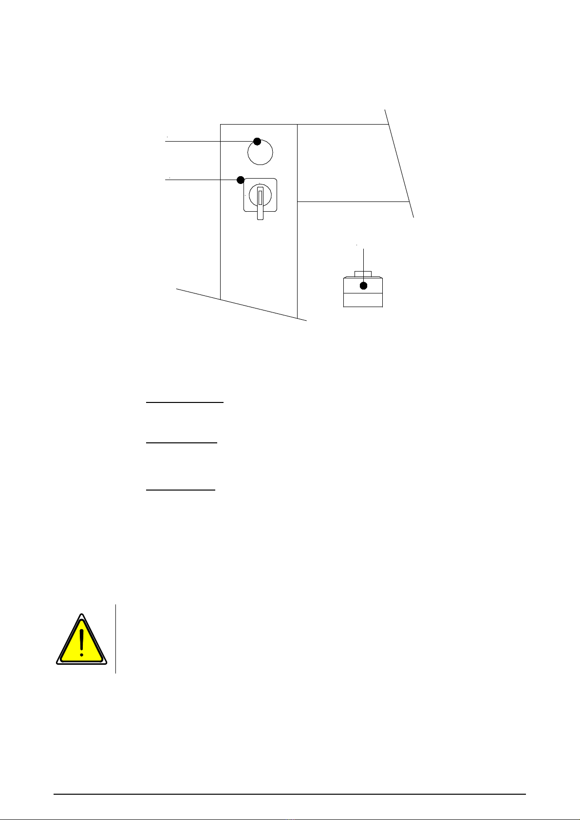
1 Control lamp
2 Main switch = O / off I / on
3 Pushbutton
(under the table top )
- press intermittently = Move aggregate forward in
stages
- press repeatedly = Aggregate runs to
neutral position
Jog mode via pushbutton:
Only authorised and trained staff are allowed to perform this
procedure!

Siebeck GmbH Translation of the original operating manual jet_in_bed_0315
Seite 14
Adjusting the zero position on the aggregate
JAG-07-050
-S3 -S2
"O"
-S10
-M2
The correct zero point (“O“) is achieved if the inserting lever JAG-07-
050 has reached its furthest left position.
The zero point is adjusted by sliding the end switch -S3.
Only authorised and trained staff are allowed to perform this
setting!!

Siebeck GmbH Translation of the original operating manual jet_in_bed_0315
Seite 15
Stripper setting
The side setting for the stripper "C" is made using the threaded pin No. 9
(group M4).
When the knotter "A" moves back, the stripper "C" must rest on knotter "A"
with pressure.
The height is set is using the rod end No. 2 (group M4).
The correct height of the stripper slot "B" to the knotter is shown in the figure
below.
A B C
Only authorised and trained staff are allowed to perform this
setting!

Siebeck GmbH Translation of the original operating manual jet_in_bed_0315
Seite 16
The story of knots
Incorrect knotting patterns and their causes
Short loops
The knotter opens too early. Shift the mount for the
cam roller for opening the knotter backwards
towards the chain wheel. The stripper does not rest
on the knotter. The string is too thin.
Knots not strong enough
Stripper slot too large. The knotter opens too early.
The string is too thin.
String not cut cleanly
The string knife is blunt. Flip or replace the knife.
String break before the knot
Sharp edges on the stripper, drawslide head, tip
up lever or knife lever.

Siebeck GmbH Translation of the original operating manual jet_in_bed_0315
Seite 17
One normal length and one short loop
The knotter is not closing properly. Tension
spring for the knotting lock is too weak. The
stripper does not rest on the knotter.
Single loop
The knot has only a single loop. The second loop
is drawn through. Increase the spring pressure on
the twine button. The lead end of the string which
protrudes from the twine button must not move
when the tying arm starts up.
Loop ends torn
Upper or lower finger of knotter or stripper has
sharp edges.
The perfect knot
A correct knot has two loops of equal length
and one short and one long end of string.
The knot is tight and hard.

Siebeck GmbH Translation of the original operating manual jet_in_bed_0315
Seite 18
Faults and their causes
Never rework the surface of the twine button housing! This
surface has an exactly specified contour. The notch is intentional
and has not been created by wear. Only ever make the necessary
settings by adjusting the string brake and twine button spring.
1. Threading: Make sure that threading has been performed properly. The
string taking the wrong course is the most common cause of string breaks
(see "Threading diagram" on pages 22-24).
2. String: The machine is set to a certain string thickness. Always use
the same quality and thickness of string in order
to achieve the best results..
a) String, which is too weak often breaks on the twine button
instead of being pulled out without hindrance
b) If the string is too thick, it will not be released by the knotter
c) String, which is too thin causes a loose knot
3. Twine button:
If you are using a good quality of string of the correct
thickness and it still breaks and leaves behind residual fibres in the twine
button, this is generally caused by excessive spring tension on the twine
button.
Reduce the spring tension. Make sure that the setting wheel re-engages
properly and the retainer screw is tightened.
4. String tension:
You achieve the best results with an even, smooth
string brake setting. Check the setting by pulling out a few metres of string
from the tying arm tube. You can change the string tension by turning the
knurled nut on the string brake
Every person on the user's premises given the task of setting
up, commissioning, operating, maintaining and repairing this
machine must have read and understood this operating
manual, and in particular the chapter "Safety".
Siebeck GmbH Translation of the original operating manual jet_in_bed_0315
Seite 19
Residual risks and incorrect operation
Residual risks and incorrect operation, which exist despite measures for
integrated safety and technical protective equipment, are described and
illustrated in the following. These risks are documented in a risk analysis and
filed by the manufacturer.
When the machine hood is open, the knotting aggregate can be driven using
jog button at reduced step by step (jog mode). The individual movement
sequences can thus be observed quite easily.
Jog mode:
Only authorised and trained staff are allowed to perform this
procedure!
In the entire area of the knotting aggregate, in particular on its
drive elements, chain wheel to roller chain, there is a
considerable risk of crushing.
Attention Risk of crushing!
Make sure you keep the opening in the middle of the table top
clear. When inserting the needle here, there is a considerable risk
of injury.
Thermal hazard!
The drive motors can reach temperatures of up to 80° C. If the
covers are removed, contact can cause injuries.

Siebeck GmbH Translation of the original operating manual jet_in_bed_0315
Seite 20
Risk of cuts.
When installing and removing the knife M.
When installing and removing the knife M, you must adhere to the following::
-Do not touch the knife blade S
Risk of injury!
-The cover plate A must be fitted as illustrated. If the cover
plate is missing, the knife M will wear quickly.
AM
S
S
Only authorised and trained staff are allowed to perform this
procedure!
Every person on the user's premises given the task of setting
up, commissioning, operating, maintaining and repairing this
machine must have read and understood this operating
manual, and in particular the chapter "Safety".
This manual suits for next models
1
Table of contents
Other Siebeck Packaging Equipment manuals


Popular Packaging Equipment manuals by other brands


AirSaver
AirSaver F2 Safety instructions, setup & installation manual

HUALIAN
HUALIAN M-PE Series Operation manual

Pro Pack Solutions
Pro Pack Solutions Eagle 710 Operation manual

Oliver
Oliver 1808-D User's operation

Kronos
Kronos H-46 Series Operation, safety and spare parts manual

Robopac
Robopac ROBOT S7 Use and maintenance manual