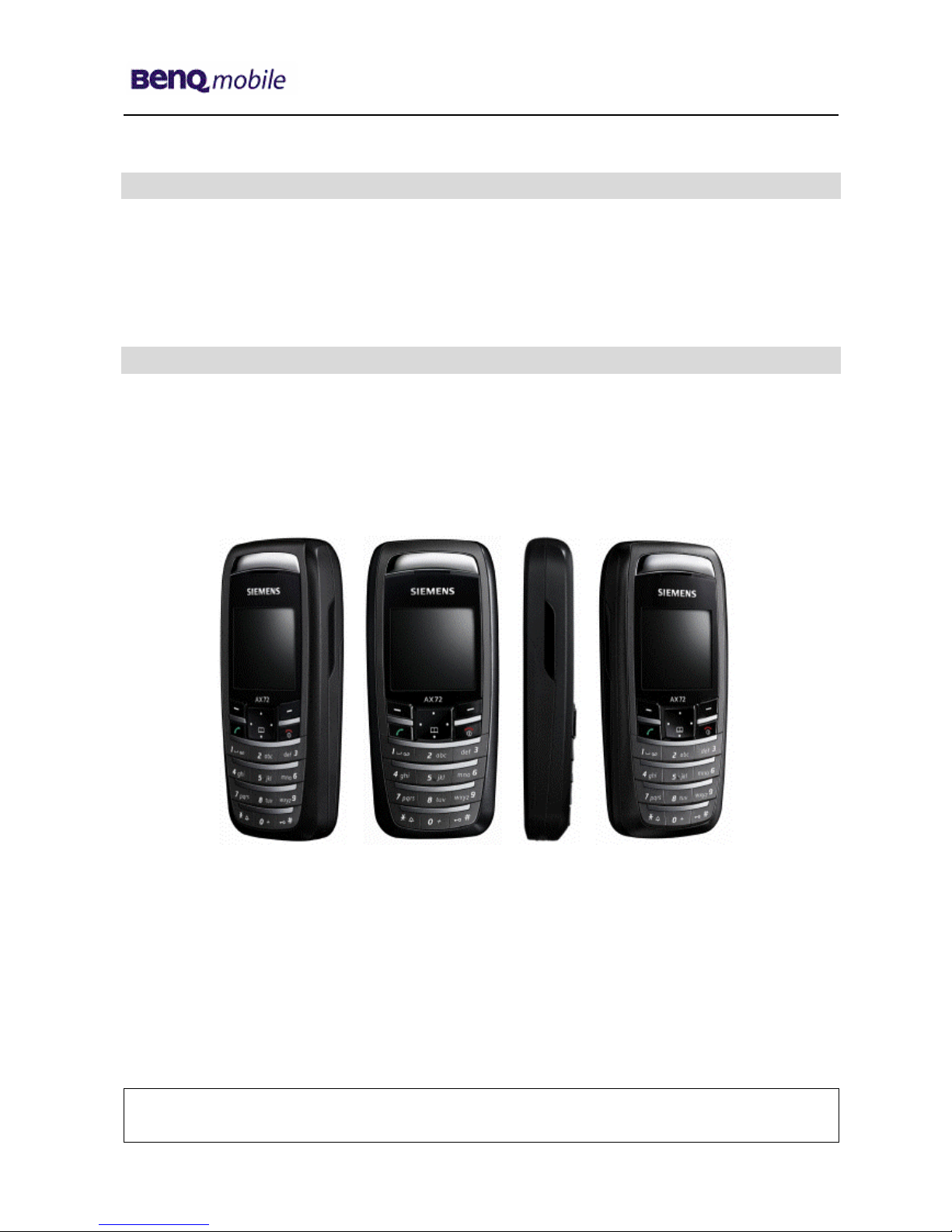
Siemens PEGASUS-DTC AX72 User manual

Release 1.1
Technical Documentation 01/2006
TD_Repair_L1-L3_AX72_R1.1.pdf Page 1 of 41
Service Manual
AX72
Level 1- Level 3 (basic)
Release Date Department Notes to change
R1.0 16.11.2005 BenQ Mobile CC S CES New document
R1.1 05.01.2006 BenQ Mobile CC S CES Part Modification
Company Confidential
2006©BenQ

Release 1.1
Technical Documentation 01/2006
TD_Repair_L1-L3_AX72_R1.1.pdf Page 2 of 41
Table of Content
1Key Feature................................................................................................................................3
2AX72 Interface to Accessories.................................................................................................5
3Unit Description of AX72 ..........................................................................................................5
4Exploded View of AX72.............................................................................................................6
5Disassembly of AX72................................................................................................................7
6Assembly of AX72...................................................................................................................12
7BenQ Service Equipment User Manual.................................................................................13
8GRT Software: Functionality Configuration........................................................................14
9GRT Software: Regular Usage ...............................................................................................16
9JPICS (Java based Product Information Controlling System)............................................21
9International Mobile Equipment Identity, IMEI......................................................................27
10 General Testing Information...................................................................................................28
11 Introduction of Service Repair Documentation Level 3 – AX72..........................................34
12 List of available level 3 spare parts.......................................................................................35
13 Hardware requirements ..........................................................................................................35
14 AX72 Board layout ..................................................................................................................36
15 SIM Card Problems .................................................................................................................37
16 IO Connector Problems ..........................................................................................................38
17 LED_Keypad illumination Problems......................................................................................39
18 Battery Connector Problems..................................................................................................40
19 Display Problems ....................................................................................................................41
Company Confidential
2006©BenQ

Release 1.1
Technical Documentation 01/2006
TD_Repair_L1-L3_AX72_R1.1.pdf Page 3 of 41
1 Key Feature
Bands • Triple Band E-GSM 900 / GSM 1800 / GSM 1900
• EGSM Phase 2 / phase 2+
• GPRS Multi Class 8
Battery • Li-Ion Battery Pack
• Nominal Voltage : 3.7V
• Nominal Capacity : 600 mAh
• GSM Capacity: 580 mAh
• Power Input: 2.0 A (0.6 ms) / 0.25 A (0.4 ms)
• Cut-off Threshold 3.2 V
Stand-by Time • up to 220 h (standard battery)
Talk Time • up to 300 min (standard battery)
SIM Card
• Small (”Plug In”) 3V SIM card (Phase II)
• To insert the SIM card, the battery pack must be
removed.
GSM Antenna • Integrated triple band antenna for EMEA/APAC.
Dimensions • 101 x 44 x 20 mm (L x W x H)
Weight • Approx. 80 g
Charging time • < 2 h for 100%
Receiver Sensitivity • GSM 900: -102dBm (Specification, static & with fading)
• GSM 1800/1900: -102 dBm (Specification, static & with
fading)
Receiver sensitivity must comply with the corresponding GSM
recommendations in all operating conditions (temperature,
battery level, etc)
Transmitter Power • GSM 900: nominal 2W (Specification: Class 4 Mobile
phone)
• GSM 1800/1900: nominal 1W (Specification: Class 1
Mobile phone)
Transmitter output characteristics is according to GSM 11.10
specification implying all specified operating conditions
(temperature, battery level ...).
Transmitter set points will be specified for GSM and PCN when
typical values and statistical values become available.
Company Confidential
2006©BenQ

Release 1.1
Technical Documentation 01/2006
TD_Repair_L1-L3_AX72_R1.1.pdf Page 4 of 41
Speech Codec
• Half Rate, Full Rate, Enhanced Full Rate and Adaptive
Multi Rate speech coders are available as standard.
Temperature
Range
• -100C to +550C (Normal operation)
• -300C to +850C (Storage capability)
Display • Type: Full Graphic
• Resolution: 130 x 130 Pixel
• No. of colours: 65K
• Technology: C-STN
• Active area: 27.3mm x 27.3mm
• Pixel size: 0.21mm x 0.21mm. (1 Pixel consists of 3
sub-pixels in red, green and blue)
• Illumination: White (3 LEDs integrated)
• Frame Rate: 15 frames/sec
12-Block Keypad • IMF technology
• 12-key-block (0-9, #, *)
• two function keys (SEND, END)
• ON/OFF key combined with the END key; the symbol
(I inside O) is used as a symbol for ON/OFF.
• 4 way-navikey
• 2 soft-keys for different SW-enabled functions
• tactile finder on key “5“
• 6 amber LEDs for keypad
Acoustics
• Three-in-one-earpiece for handset, handsfree and
ringing tones
• Omnidirectional microphone
• Loud signal emitter (soundringer) (>100dB(A) SPL
@5cm, 'Hongkong-Spec.') only for rectangular sound
signals (NOT POSSIBLE for Soundringer melodies)
• Polyphonic ringer tones 16 voices
• Different selectable volume levels for handsfree, handset
and ringer mode (for the amount see SW product
description)
Company Confidential
2006©BenQ

Release 1.1
Technical Documentation 01/2006
TD_Repair_L1-L3_AX72_R1.1.pdf Page 5 of 41
2 AX72 Interface to Accessories
There are no specific mechanical interfaces to the car cradle. The car cradle is designed to
fit the existing design. The I/O-Connector (Lumberg-slim-connector) is in use. The
compatible interface is suitable to use the travel charger.
3 Unit Description of AX72
The AX72 is designed as a Mono Block with non-exchangeable housing. The Upper case,
lower case and battery cover are painted parts. IMD Lens will be mounted by Ultrasonic,
Display, 130X130; semi-bridgeless keypad, 4-way Navi-Key, 12 keys block; IMD lens; IRDA
window; No ID concept will be realized on Battery cover.
Company Confidential
2006©BenQ

Release 1.1
Technical Documentation 01/2006
TD_Repair_L1-L3_AX72_R1.1.pdf Page 6 of 41
4 Exploded View of AX72
Upper case shell
Ke
yp
ad
Earphon
Displa
Main board
Microphon
Vibramotor
U
pp
er case shell
Screw
Batter
y
Li-ion
Batter
y
cove
r
Company Confidential
2006©BenQ

Release 1.1
Technical Documentation 01/2006
TD_Repair_L1-L3_AX72_R1.1.pdf Page 7 of 41
5 Disassembly of AX72
All repairs as well as disassembling and assembling have to be carried out in an ESD
protected environment and with ESD protected equipment/tools. For all activities the
international ESD regulations have to be considered.
For more details please check information in c – market
https://market.benqmobile.com/SO/welcome.lookup.asp
There you can find the document “ESD Guideline”.
Step 1
Front view of the AX72
Step 2
Back View of the AX72
Step 3
Remove Battery cover.
Step 4
Company Confidential
2006©BenQ

Release 1.1
Technical Documentation 01/2006
TD_Repair_L1-L3_AX72_R1.1.pdf Page 8 of 41
Remove Battery
Step 5
Remove SIM Card
Step 6
Remove the 4 screws (as indicated) with T5 Plus screw driver.
Company Confidential
2006©BenQ

Release 1.1
Technical Documentation 01/2006
TD_Repair_L1-L3_AX72_R1.1.pdf Page 9 of 41
Step 7
Remove Vibramotor
Step 8
Remove Microphone
Step 9
Remove Main board.
Company Confidential
2006©BenQ

Release 1.1
Technical Documentation 01/2006
TD_Repair_L1-L3_AX72_R1.1.pdf Page 10 of 41
Step 10
Remove Display module. Place foil over Display module for protection
Step 11
Remove Earphone
Step 12
Company Confidential
2006©BenQ

Release 1.1
Technical Documentation 01/2006
TD_Repair_L1-L3_AX72_R1.1.pdf Page 11 of 41
Remove Keypad
Step 13
Fully disassembled AX72
Company Confidential
2006©BenQ

Release 1.1
Technical Documentation 01/2006
TD_Repair_L1-L3_AX72_R1.1.pdf Page 12 of 41
6 Assembly of AX72
For the reassembly of the AX72, reverse the disassembly procedures from Step 12 to
Step1. However there are some areas to be taken note of during reassembling of the
phone.
During the installation of the SIM card, make sure that the SIM card is inserted properly and
that the golden contact area is facing downwards. Insert the SIM card downwards to lock
the SIM card into position.
Installation of the SIM card
During the installation of the battery, make sure that the hinges are properly in place (See
picture below). Otherwise the battery will not be able to fit into the phone properly.
When placing the screws, set Torque to 17cNm.
Company Confidential
2006©BenQ

Release 1.1
Technical Documentation 01/2006
TD_Repair_L1-L3_AX72_R1.1.pdf Page 13 of 41
7 BenQ Service Equipment User Manual
Introduction
Every LSO repairing BenQ handset must ensure that the quality standards are observed.
BenQ has developed an automatic testing system that will perform all necessary
measurements. This testing system is known as:
BenQ Mobile Service Equipment
• For disassembling / assembling
Torque – Screwdriver
Part Number: F30032 – P 228 – A1
Opening tool
(Case opening without
destroying)
Part Number: F30032 – P 38 – A1
Alternative Opening tool
Part Number: F30032 – P583– A1
Tweezers
• For testing
All mobile phones have to be tested with the GRT – Software. The service partner is
responsible to ensure that all required hardware is available.
For additional Software and Hardware options as well as the supported GRT equipment,
please check the GRT User manual.
Company Confidential
2006©BenQ

Release 1.1
Technical Documentation 01/2006
TD_Repair_L1-L3_AX72_R1.1.pdf Page 14 of 41
8 GRT Software: Functionality Configuration
Step 1: Select „Settings >> SWUP / JPICS”
Step 2: Proceed as follows:
Select all required Variants you need to repair (click onto the “+” in
front of the product name.
Check Com-Port setting. If necessary change it
Check speed setting. Select always the lowest speed if your PC
does not have a fast serial card
Enter the value for “JPICS Server Timeout”. Be careful, this value
defines how long GRT tries to reach the server until you get an
error message. Do not select a very long time
2
4
1
3
Company Confidential
2006©BenQ

Release 1.1
Technical Documentation 01/2006
TD_Repair_L1-L3_AX72_R1.1.pdf Page 15 of 41
Step 3: Connect to GRM Server
• Choose in the section „GRM” the „Connect to GRM Database“ functionality
3
It you IT infrastructure parameter
have changed, use this button to
move to the configuration mask
2
A
ctivate always both boxes if you
connect to the database. Start
with “Connect”
1
Enter your GRT-Username and
Password into this fields
• End the connection with a click onto the „Exit button“ (appearing after successful data
exchange)
GRT Software has now finished all required settings and configuration tasks. All
files have been down- and uploaded.
In dependency of the selected number of mobile phones and variants the volume
of transferred date could be (~100MB)
Company Confidential
2006©BenQ

Release 1.1
Technical Documentation 01/2006
TD_Repair_L1-L3_AX72_R1.1.pdf Page 16 of 41
9 GRT Software: Regular Usage
Step 1: Select the section SWUpdate
Step 2: Choose the area you want to work with
• Personal Repair
Personal Repair is always accessible. Basis for the decision if a SW-Update is
authorised by Siemens is the so called Service Release-Table .
Example:
Mobile Phone has already SW50. Service -Release-Table shows SW50. In this case
SW-Update is not necessary and therefore not authorized
In any case customer data can be erased on request. (xfs and mapping have to be
activated) Of course JPICS hardware and authorisation have to be available.
• Operator SWAP
This area is only accessible if you are released by the service management to
perform SW-Updates for Net-Operators. Basis for the decision if a SW-Update is
authorised by Siemens is the so called Master-Table.
Customer data will be erased without any exception and any chance to influence by
the user. JPICS hardware and authorisation have to be available.
• Operator SWUpdate
This area is only accessible if you are released by the service management to
perform SW-Updates for Net-Operators. Basis for the decision if a SW-Update is
authorised by Siemens is the so called Master-Table.
Like in “Personal Repair” customer data can be erased on request. (xfs and mapping
have to be activated) Of course JPICS hardware and authorisation have to be
available.
Company Confidential
2006©BenQ

Release 1.1
Technical Documentation 01/2006
TD_Repair_L1-L3_AX72_R1.1.pdf Page 17 of 41
9.1 Window explanation
This general explanation is valid for all SW-Update channels
(Personal Repair, Operator SWAP, Operator SWUpdate)
After using „Check Variant“ Phone IMEI-
Number will be shown here
Start button for SW-
Update
Stop / leave SW-Update
Shows the different SW –Versions
a) SW inside the mobile phone
b) Version of Service Release Table
SW
c
)
Version of Master Table SW
Window to select the mobile
phone CPU
Select boxes for:
Content = xfs
Settings = mapping
A
ttention:
A
ctivation of the boxes
will cause erase o
f
customer date while SW-
Update
Automatic read out function of
phone type/Variant. Appearing
in the window above.
Remarks:
In case of malfunction please check
o Is the correct phone type selected
o Is the correct COM-Port selected
o If a variant is missing, move back to Settings select the missing variant and
conncet the GRM Server. Then continue with SW-Update.
Company Confidential
2006©BenQ

Release 1.1
Technical Documentation 01/2006
TD_Repair_L1-L3_AX72_R1.1.pdf Page 18 of 41
9.2 Case 1: Personal Repair (green)
Step 1: Carry out step 1 – 4 to start SW-Update.
1
Select the mobile phone CPU type
3
4
Choose if customer data shall be erased.
If “Yes” activate the boxes in front of xfs
and mapping
Read out phone type/Variant.
>>Appears in the window
above.
2
Start SW-Update
Remarks:
- The decision about a Siemens authorised SW-Update depends only on the
Service Release-Table .
- The SW which is booted by GRT can be below the SW mentioned in the
Service Release Table, if this SW is not released for the Net-Operator
- If xfs and mapping are activated, GRT will erase in any case the customer
data even if the action is cancelled.
- If the user wants to download another variant then the automatically identified
one, he has simply to select another variant from the list. Afterwards he has to
start the SW-Update
Company Confidential
2006©BenQ

Release 1.1
Technical Documentation 01/2006
TD_Repair_L1-L3_AX72_R1.1.pdf Page 19 of 41
9.3 Case 2: Operator SWAP (red)
Step 1: Carry out step 1 – 4 to start SW-Update.
1
4
3
Read out phone type/Variant.
>>Appears in the window
above.
2
Select the mobile phone CPU type
Start SW-Update
Choose if customer data shall be erased.
If “Yes” activate the boxes in front of xfs
and mapping
Remarks:
- The decision about a Siemens authorised SW-Update depends only on the
Master-Table.
- The user has no chance to influence the decision
- Xfs and mapping are always activated there is no chance to deactivate them.
GRT will erase in any case the customer data even if the action is cancelled. If
the user wants to download another variant then the automatically identified
one, he has simply to select another variant from the list. Afterwards he has to
start the SW-Update
Company Confidential
2006©BenQ

Release 1.1
Technical Documentation 01/2006
TD_Repair_L1-L3_AX72_R1.1.pdf Page 20 of 41
9.4 Case 3 Operator SWUpdate (blue)
Step 1: Carry out step 1 – 4 to start SW-Update.
1
3
Choose if customer data shall be erased.
If “Yes” activate the boxes in front of xfs
and mapping
4
Read out phone type/Variant.
>>Appears in the window
above.
2
Select the mobile phone CPU type
Start SW-Update
Remarks:
- The decision about a Siemens authorised SW-Update depends only on the
Master-Table.
- The user has no chance to influence the decision
- Xfs and mapping can be activated on demand. GRT will erase in any case
the customer data even if the action is cancelled.
- If the user wants to download another variant then the automatically identified one, he
has simply to select another variant from the list. Afterwards he has to start the SW-
Update
Company Confidential
2006©BenQ
Other manuals for PEGASUS-DTC AX72
3
Table of contents
Other Siemens Cell Phone manuals

Siemens
Siemens C55 User manual

Siemens
Siemens SL45i User manual

Siemens
Siemens CC75 User manual

Siemens
Siemens A50 User manual

Siemens
Siemens C55/2128 User manual

Siemens
Siemens A70 User manual

Siemens
Siemens C62 User manual

Siemens
Siemens CL75 Setup guide

Siemens
Siemens S75 Setup guide

Siemens
Siemens AF51 User manual

Siemens
Siemens Gigaset S45 User manual

Siemens
Siemens S55 User manual

Siemens
Siemens A56 User manual

Siemens
Siemens SL45 User manual

Siemens
Siemens C60 User manual

Siemens
Siemens XELIBRI X8 User manual

Siemens
Siemens Emoty User manual

Siemens
Siemens M50 User manual

Siemens
Siemens S65 User manual

Siemens
Siemens S66 User manual