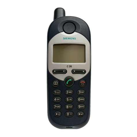
Siemens M35 User manual

Local Service Organization Service Manual
M35 Series
M35 Series
S I E M E N S C O M M U N I C A T I O N S U N L I M I T E D
V1.0

Table of Content
CHAPTER 1
Cellular Co unication
Coverage Concept 1
GSM Network Architecture 2
Subscriber Identity Module 3
SIM Application Toolkit 4
Extended GSM 900 - EGSM 5
Built-in Mode 5
Data Application 6
CHAPTER 2
Level 2 Service Guide
Introduction 7
M35 Series Technical Infor ation 8
Accessories 10
General Infor ation 11
M35 Series Exploded Diagra 13
Mechanical Concept 14
Hardware Concept – Block diagra 15
Hardware Description 16
Power Supply Concept 18
Over voltage Condition 18
Battery Charging 18
Short Circuit Protection 19
Nor al Charging 19
Deep Discharge Battery 20
M35i Spare Parts Level 1 & Level 2 21
Disasse ble the M35 22
Disasse ble/Asse ble Lower Housing 24
Disasse ble/Asse ble Control Board Assy 24
Disasse ble/Asse ble Display Module 25
Disasse ble/Asse ble Upper Housing 26
Asse ble the M35 27
Mobile Software Progra ing 29
Language Groups 31
Custo er Specific Initialization 33
International Mobile Equip ent Identity 33
Phone Unblocking 34
CHAPTER 3
Sie ens Service Equip ent
Introduction 36
Other equip ent 38
Software Installation 39
Configuring the test software 40
Running the test sequence 41
ANNEX A 45
ANNEX B 48
CHAPTER 4
Level 2.5 Repair Docu ent
Introduction 49
Antenna Connector 51
Ringer 54
Botto Connector (Lu berg) 57
Display Connector 61
Keyboard LED 65
Display LED 68
Infrared Diodes 72
ANNEX C
PC Adapter Cable & Accessories M35 75
Power Plug for M35 76
Car installation Ratio Unit, M35 77
Car Installation kit Handfree kit 78
Car Installation kit Handfree Pro. 79
Car Installation Co fort GPS, M35 80
References 82
V1.0 ii

Cellular Co unication
Coverage Concept.
he cellular syste s is ade up of nu erous trans itting and receiving
sites, whose individual coverage areas partially overlap. The concept
of frequency re-use, sa e frequency is used by several sites, allows a
high traffic density in a wide area. Due to the li ited trans ission range of the
ter inals, cellular syste s are based on a large nu ber of base stations on
the infrastructure side, scattered over the area to cover, with each covering a
fairly s all geographical zone called cell. Cells are often represented by
hexagons (see figure 1.1.).
T
FIGURE 1.1 CELLULAR COVERAGE REPRESENTATION.
V1.0 iii
Chapter
1

GSM Network Architecture.
GSM network can be broadly divided into three broad parts, na ely:
1. Mobile Station(MS) carried by the subscriber,
2. Base Station Sub-syste (BSS) which controls the radio link with the obile station.
3. Mobile Switching Center(MSC) which perfor s the switching of calls between the obile
users, and between obile and fixed network users.
FIGURE 1.2 GSM ARCHITECTURE
Each obile station is given a unique identity. As soon as the obile phone is turned on, it
registers with the network and is authenticated, as such the network could always find the obile
phone.
Larger a ount of data is being exchanged to and fro the following functional blocks in the
MSC:
Visitor Location Register, VLR
Stores infor ation about obile subscribers that enter it coverage area which is associated with
the geographical area where the obile is currently roa ing. When there is an inco ing call for
the obile, the HLR is interrogated about the present address of the VLR.
Home Location Register, HLR
A database that contains all data concerning the subscription of the obile subscriber, i.e. their
access capabilities, subscribed services, and supple entary services. It also contains
infor ation about the VLR that is handling the obile station currently. When the obile
changes location, the HLR is updated accordingly. It also provides the MSC with infor ation
about the MSC area where the obile is actually located to allow inco ing calls to be routed
i ediately to the called party.

Authentication Center, AUC
Stored infor ation that is necessary to protect co unication through the air interface against
any intrusions. The legiti acy of the subscriber is established through authentication and
ciphering, which protects the user infor ation against unwanted disclosure.
quipment Identity Register, IR
An option the network operator can use to enforce security. With this feature the network can
identify defective or stolen obile that ay not be used in the network.
Subscriber Identity Module(SIM)
SIM is a s art card which has a co puter and e ory chip that is per anently installed in the
obile equip ent. It co es in either the size of a credit card or s aller version known as the
plug-in SIM.
The subscriber infor ation, which includes a unique nu ber called the International Mobile
Subscriber Identity (IMSI) is stored in the SIM card. SIM card identifies the subscriber to the
network.
FIGURE 1.3 INSERT SIM CARD
Figure 1.3 illustrates the steps for inserting the SIM card into the M35i series.

To protect the SIM card fro i proper use, a security feature, a four digits personal identification
nu ber(PIN), is built in. The PIN is stored in the card and can be changed by the subscriber.
PIN2 is required for additional funtions available with a special SIM card (Consult the operator for
ore infor ation about the PIN.
A code (PUK) is provided for unlocking the SIM card if the SIM card is blocked
Change PIN Procedures.
CHART 1.1 PIN CONTROL
SIM Application Toolkit
SIM Applications Toolkit (SAT) allows the flexibility to update the SIM, to change the services
and download new services over the air. In the SAT specification, the short essage service is a
key echanis for personalizing the SIM in each user’s GSM phone. It is designed as a client-
server application. M35i series supports SAT Class 3 specification.
€
MENU
SETUP
SECURITY
CODES
CHANGE PIN CHANGE PIN2
{ENTER PIN NUMBER}
CHANGE
{ENTER NEW PIN} AND PRESS OK KEY.
{ENTER NEW PIN) AND PRESS OK KEY.

When active, the na e of the service ay appear in the enu, and there will be sub- enu if
ore than one application is active. Figure 1.4 is the SAT icon.
FIGURE 1.4 SAT ICON
xtended GSM 900, -GSM
This is a new standard that allows Network Operators to increase their capacity through an
extended frequency. The frequency range of E-GSM is as follows:
•Mobile Trans it: 880 – 915 MHz
•Mobile Receive: 925 – 960 MHz
M35i series is a GSM Phase 2 / Phase 2+ Dualband E-GSM / GSM 1800 obile phone.
Built-in Modem.
M35i has an integrated ode for direct data co unication using the data cable as shown in
Figure 1.5. M35 do not have the built–in soft ode for Data Service of GSM network.
FIGURE 1.5 DATA CABLE.

Data Application Support
Mode driver confor s to V.25 co and set, and trans ission speed confor s ITU-T-
standard of V.22bis. (2400, 4800,and 9600 bits/sec).
Facsi ile confor s to Service Class 1, group 3 and operate at 2400, 4800, 7200 and 9600 bit/s.
Data services via GSM network up to 9600 kbps, and re ote control using cellular AT
co ands.
Internet access via the M35i is possible with the inclusion of Wireless Application Protocol (WAP)
browser 1.1.
Level 2 Service Guide
Introduction
The chapter is intended to help you carry out repair up to Level 2 on the M35 series obile
phone.
The repair for international version and Asian variants are identical unless otherwise noted,
therefore the description herein is confined to M35i only.
All repairs have to be carried out in an environment set up
according to ESD regulations defined in international standards.
ESD procedure is available from your Service Manager. Ask for
ASC/T001/ 8
Chapter
2
e

M35i Technical Information
Syste GSM Phase 2, Dual Band
EGSM 900, Class 4(2 Watt)
GSM 1800, Class 1(1 Watt)
Operating Voltage 3.6V
Size(LxWxH) 118 x 47 x 22.6
Volu e 99c 3 including battery (approx)
Weight 130g including battery (approx)
Battery(Standard) NiMH, 500 AH(Standard)
Li-Ion, 600 AH(Optional)
Standby ti e150 to 180 hours (standard battery)
Talk ti e190 to 300 inutes (standard battery)
Charging Ti e 2 hours
SIM support Plug in card 1.8 V or 3V, SIM Application Tool Kit Class 3
Antenna Integrated.
Speech codec Triple rate nhance Full Rate
Full Rate
Half Rate
Display 101 x 54 pixel graphical display with up to 5 lines
12 x 12 font size for Chinese
Keypad 12 nu eric keys(10 nu eric, #, *)
3 function keys(Send, End-ON/OFF, Phonebook)
4 ultifunctional softkeys
Key Sound Click/DTMF/None
Key Lock Activation and Deactivation by #-key or
Auto atic.
1 Actual ti e dependent on the network.

Dialing 10 redial nu bers
Last 10 inco ing with date/ti e sta p
Last 10 outgoing calls
Last 10 issed calls with date/ti e sta p
Ringer On/Beep/Off
Up to 22 elodies and 5 volu e settings
(Melody Co poser and Crescendo Ringing)
Volu e Adjustable in 4 levels during call via softkey
Silent Alert Built-in vibrator
Phone Book Storage depends on the SIM card capacity
Storage of up to 100 list in the phone.
SMS Support MT, MO, CB
Predictive Text Input, Tegic T9.
Supple entary Call Forwarding, Call Hold, Call Wait,
Services Multiparty Conference, CLIP, CLIR, AoCC
AoCI, FDN, LND USSD and SAT
Ciphering A5/1 and A5/2 supported
PIN control PIN 1 & 2 Code Control
Phone code 4 to 8 digit code
Network function Auto atic and anual network selection
Chipset Sie ens E – GOLD
WAP Browser1Version 1.1
Other FeaturesClock / Alar
Alar List2
Built-in ode 3
Calculator4
Currency Converter
4 Ga es
7 User Profiles
1 Only for Model M35i.
2 Not available in M35 International version.
3 Not available in M35 International version.
4 Not available in M35 International version.

Accessories:
1. Standard Battery L36880-N4001-A100
2. Optional Battery L36880-N4001-A101
3. Standard Charger L36280-Z4-CXXX (Country Variant)
4. Travel Charger L36880-N4001-A103 (EU) / A104 (UK)
Si ilar to standard charger with an universal input voltage fro 90 ~ 240V
4. Desk Top Charger L36880-N4001-A102
5. Belt Clip L36880-N4001-A113
6. Headset L36880-N4001-A123
7. Antenna Cradle L36880-N4001-A110
8. Car Charger Cable L36880-N4001-A108
9. Car Kit Portable1L36880-N3015-A117
10. Car Kit Co fort L36880-N4001-A111
11. Car Handset2L36880-N3015-A123
12. Designer Cases L36880-N4001-A119
13. Soft Data Link 3.0 L36880-N4001-A122 (Not for 3518i)
14. Data Cable3L36880-N3101-A102
15. Car Kit Professional Voice L36880-N4001-A124
16. Data Cable Professional4L36880-N3101-A112
1 Sa e as C25(88)
2 Sa e as C25(88)
3 Sa e as C25(88)
4 Sa e as C25(88)

General Information
Information
Due to different require ents of the arkets, the M35 has different variants, which broadly
classified under International version and Asian version. Marketing na e for international version
is M35 or M35i, whereas Asian version is na ed M3508 or M3508i.
Difference between M35(18) and M35(18)i
M35(18)i obile software has WAP Browser 1.1 incorporated thus enabling user to surf the
Internet and it have the built-in soft ode for GSM Data Service. The non-Wap M35(18) do not
have the soft ode .
The differences between the M35 and M35i are the hardware and software. The e ory size of
M35 is 16MB and that of M35i is 32MB.
There are also two variants for 3518, one without the WAP browser is 3518 and that with WAP
browser version 1.1 is 3518i.
Wireless Application Protocol, WAP.
Wireless Application Protocol takes a client-server approach that uses the in-built icro-browser
to ake a request, in wireless arkup language (WML), for infor ation or service. The request
is passed to a WAP Gateway which then retrieves the infor ation fro a Internet server, in
HTML for at, and translate it into WML. The requested infor ation is then sent to fro the WAP
Gateway to WAP client ( obile) using the available and ost appropriate obile network bearer
services.
Wireless Protocol Stack.
Wireless Application Environ ent (WAE)
Wireless Session Protocol (WSP)
Wireless Transaction Protocol (WTP)
Wireless Transport Layer Security (WTLS)
Wireless Datagra Protocol (WDP)
Bearers e.g. Data, SMS, USSD
TABLE 1..1 WAP PROTOCOL STACK
1. Wireless Application Environ ent
Defines the user interface on the phone. WAE contains the WML,WML script and the
wireless telephony application (WTA).
2. Wirelss Session Protocol
Link the WAE to two session services – one connection oriented operating above the WTP
and a connectionless service operating above WDP.
3. Wireless Transaction Protocol
Runs on top of the datagra service and part of the standard suite of TCP/IP protocols, to
provide a si plified protocol suitable for low bandwidth obile station.

4. Wireless Transport Layer Security
WTLS incorporates security features that are based upon the established Transport layer
Security (TLS) protocol standard, that include data integrity checks, privacy on the WAP
Gateway to client leg and authentication.
5. Wireless Datagra Protocol
Allows WAP to be bearer independent by adapting the transport layer of the under-laying
bearer. WDP presents a consistent data for at to the higher layer on the WAP stack.

M35 Series Mechanical Diagram
FIGURE 2.1 M35I MECHANICAL DIAGRAM.
Please take note that the nu ber(s) used here IS NOT the part
nu ber, DO NOT used it in your spare parts purchase order.
A l w a y s r e f e r t o t h e S E R V I C E P A R T P R I C E L I S T
f o r y o u r s p a r e p a r t o r d e r .

Mechanical Concept
Note: All numbers refer to mechanical drawing in Figure 2.1.
The echanical concept of the M35 differs in various points fro the one of the other Sie ens
obile telephones.
The first thing you will experience is how the housing is locked. In M35 no screws are used to
keep the housing closed. Also inside the telephone no screws are used any ore. To open the
housing, which is kept closed by catches only, a special opening tool has been defined. Once
the phone is open the catches will be da age and a new housing need to be used. For details
on disassembly tool please refer to Photo 2.5 in the Disassembly Section of this chapter.
Inside, the M35 consists of just one board (1010) which carries display odule(1170), control
part and RF section of the obile.
The display odule (1170) is connected to the board by a flexible cable which is inserted into a
plug. In case the display is defective electrically or echanically it can be exchanged very easily.
M35i does have an external connector of a new type. Since S6 a so called “Molex”-connector
was used, which also offered the possibility to connect an external antenna to it. The new
“Lu berg”-connector which is used in M35 does not feature such a connection, because the
connector for external antenna is located at the back side of the upper end of the obile, close
to the internal antenna. As a consequence of this there is no need any ore for a RF cable
ounted to the board nor for a RF plug on it to connect this cable. This i proves RF-properties
of the obile and lowers production costs.
To be able to do easure ents on and software update of the telephone, an adapter cable
between Molex and Lu berg connector will be available. See photos in Additional Tools of
Chapter 3.
M35 antenna is an integral part of the lower case shell (1030). The antenna can only be
changed by open up the M35i phone and replace the housing.
The M35i is a dual-band mobile operating on GSM 00 and
GSM1800, the antenna is an integral part of the lower housing.
The keypad, the icrophone and the loudspeaker are ounted into the upper case shell (1020).
Make sure that the icrophone and the earphone contact springs are not dirty or da aged
during repair process.
The dust protection fra e and the display window are included in the display odule(1170).

Hardware Concept – Block Diagram
FIGUR 2.2 M35 BLOCK DIAGRAM.

Hardware Description
The handset consists of the following ajor integrated circuits:
1) E-GOLD – PMB2851E
This IC is a co bination of icroprocessor, signal processor and real-ti e clock.
The icroprocessor part of this co ponent is responsible for controlling the keyboard, SIM-
Card, Flash and RAM. Further ore it controls the power saving, power up/power down of the
RF odule and sets the a plification of the PA.
The signal processor part of PMB 2851E is responsible for processing the Rx I/Q signals
(filtering, equalizing, speech and channel decoding).
Further ore it does the speech and channel encoding and the GSMK odulation of the Tx
I/Q signals. The Voice CODEC part is used to realize advanced features regarding coding of
the speech signal. These are:
•Halfrate-Encoding
•Halfrate-Decoding
•Enhanced Fullrate Encoding
•Enhanced Fullrate Decoding
•Voice Activity Detection
•Co fort Noise
2) GAIM – PMB2 06
The GAIM (GAIM = GSM Analog Interfacing Module) provides the interface between the
analogue and its digital representation signals (Base-band I/Q, Voice-band, PA-control,
Voltage & Te perature Measure ent - Charging control).
3) 13Mhz Ref Oscillator Circuit -
This circuit provides the following ain functions:
•Generate 13Mhz clock signal for Logic Circuits – SIN13M.
•Generate 13Mhz reference signal for the PLL circuits for the Tx & Rx of GSM RF signal.
•Received the frequency steering control AFC_PNM fro the HiGOLD IC for fine tuning
of the Tx & Rx frequency.
•Te perature dependent resistor sited near the 13MHz oscillator easure the
environ ent te perature.
4) Power Supply ASIC – D0767BA

This circuit provides the following ain functions:
•Control of switch on of the Mobile phone by ON/OFF button, Ext Power (Charger) or real
ti e clock.
•Watchdog onitor – switch off the obile phone if no proper Watchdog signal send fro
HiGOLD IC.
•Voltage supply to the logic circuits – 2.90V, 2.65V & 1.92V, Si card & real ti e clock in
HiGOLD IC.
•Switch on the linear regulator to supply the 2.8V for the13Mhz Oscillator circuit.
•RESET signal for the logic circuit.
•Charge control signal for switching the charge FET.
•Low battery detector.
•Over voltage protection.
5) Receiver Circuit – Bright II HD155124F
This circuit provides the following ain functions:
•Low Noise A plifier (LNA) with a fixed a plification of +20dB to a plify the input RF
signal.
•Mixer to ix down the RF signal to the Inter ediate Frequency (IF)
•Progra able IF a plifier with a dyna ic range of 60dB ( -10dB ~+50dB in steps of
2dB).
•Mixer to ix down the IF signal to the baseband, generating and inphase (I) and a
quadrature (Q) signal and feed the GAIM IC base-band signal, RX I/Q for the decoding
of the digital signal for the HiGOLD IC.
6) Transmitter Circuit – Bright II HD155124F
The GAIM IC generate the MOD I/Q base-band signal under the control of the HiGOLD IC
and feed the IQ odulator of the Bright II IC. The Bright II IC provides the IF synthesizer,
the I/Q odulator, prescaler to regulate the dual-band TX-VCO and feed the odulated GSM
signal to the PA.
The telephone support only 1.8V and 3V SIM card
For user with 5V SIM card, he need to upgrade the SIM card
through his service provider/network operator

Power Supply Concept
The M35i has two ain power inputs:
1. Battery voltage(3.6V) connected at the battery contact
2. Charging voltage(6.5V) delivered by the different charger type(see Accessory List) via the
Lu berg connector at the botto of the telephone.
Since the battery voltage is supplying the power supply ASIC, it is always needed to operate the
phone. You cannot switch on the handset if the battery voltage is not present.
Fro the battery voltage, all other supply voltages are derived and controlled by the power
supply ASIC.
The RF power a plifier is directly connect to the battery, a bad battery with high internal
resistance can cause alfunction of the M35i phone.
The Logic odule uses 1.92V, 2.65V & 2.9V generated by voltage regulators inside the ASIC.
Further ore, the ASIC generates the supply voltage for the SIM card and the RESET signal for
the logic devices.
The ASIC also checks the presence of the watchdog signal fro the icroprocessor and
provides the switching on functionality (ON_OFF button or Ignition signal).
Wrong polarity or battery voltage setting that exceed the +6.5V
could damage the phone.
Over-voltage Condition
•Battery voltage
If the supply voltage rises above 6.2V, the phone will switch off and it cannot be switched on
again before the voltage is lower than 6.2V. If the supply voltage rises above 7V, the phone
can be da aged
•Charging Current
The charging current ust not rise above 1A or a track fuse in the phone will blow. As a
result charging the battery will no longer by possible.
Be careful with NON-original SIEMENS accessories or chargers.
Make sure that the charging current is limited to value below 1A.

Battery Charging
M35 series uses a Nickel Metal Hyride (NiMH) 500 AH battery pack as standard battery. It also
support the Lithiu Ion 600 AH battery pack (For S35i phone) as optional battery for custo er
want longer talk ti e.
PHOTO 2.3 M35i SERIES INSERTING BATTERY.
For M35, BATT+ has a voltage level fro +3.0V to 5.5V, and a BATT_TEMP contact is used for
detecting abnor al increase in te perature of the battery.
If the temperature is too high or too low, there is a high probability
that the battery is not charged. To enable the charging process
again, battery and phone needs to cools down or warm up. Battery
replacement is not required.
A v o i d s h o r t i n g t h e b a t t e r y t e r m i n a l s .
Short Circuit Protection
For the Nickel Metal Hydride battery, a polyswitch in the battery pack protecting the battery fro
short circuit and it should reset by itself after so e ti e re oving the short circuit.
For the Lithiu Ion battery, it is short-circuit protected by an electronics fuse. The fuse will be
activated in case a too high current is drawn. This fuse will not reset auto atically.
The resetting of the L-ion battery fuse can be done with either of the following procedures:
1. Insert the battery into the M35 and then connect the rapid charger to the phone. Wait for
approxi ately 10 second, then the obile can be turned on again.
2. Plug the battery separately into the desktop charger. The fuse is reset i ediately.
3. Insert the battery into the M35 and put the phone into the desktop charger. Wait for
approxi ately 10 second, then the obile can be switched on.
Normal Charging
The battery can be charged when it is inserted into the phone. The charging process is
co pletely controlled by the obile. Charging can be done with any of the following accessory:
1. Rapid charger
2. Travel charger
3. Car charger
4. Desktop charger
Table of contents
Other Siemens Cell Phone manuals

Siemens
Siemens C62 User manual

Siemens
Siemens M75 User manual

Siemens
Siemens M65 User manual

Siemens
Siemens Be inspired M55 User manual

Siemens
Siemens A62 User manual

Siemens
Siemens C70 User manual

Siemens
Siemens Be inspired M55 User manual

Siemens
Siemens C55 User manual

Siemens
Siemens A31 User manual

Siemens
Siemens A71 User manual

Siemens
Siemens PEGASUS-DTC AX72 User manual

Siemens
Siemens optiPoint WL1 professional User manual

Siemens
Siemens ME75 User manual

Siemens
Siemens HiPath C10 User manual

Siemens
Siemens SX66 User manual

Siemens
Siemens C25 User manual

Siemens
Siemens Gigaset SL75 WLAN User manual

Siemens
Siemens S35i User manual

Siemens
Siemens AX75 User manual

Siemens
Siemens Gigaset SL75 WLAN User manual